1
co c c: ~ 1../.1 i=l m
i=»PlOFESSION AI
SEPliES
Remote Start
Installation Guide
for models:
ca4054
ca4554
2014 Voxx Electronics Corporation. All rights reserved.
4280596
Before You Begin ......................................................................................... 3
Wire Connection Guide ............................................................................... 4
4 Pin Main Harness ................................................................................... 5
3 Pin Parking Light Harness ...................................................................... 6
6 Pin Start Harness ................................................................................... 7
4 Pin Alternate Harness ............................................................................. 8
2 Pin Door Lock Output Harness ............................................................... 9
Additional Ports ......................................................................................... 10
Antenna I LED I Programming Port ........................................................ 10
OBI Port ................................................................................................... 10
Telematic Interface Port ........................................................................... 10
Set Up & Programming ............................................................................. 11
Transmitter Programming ........................................................................ 11
Manual Feature Programming ................................................................. 11
Programming Feature Banks .................................................................. 12
Tach Programming .................................................................................. 14
Smart Tach less Mode .............................................................................. 14
Feature Descriptions ................................................................................. 15
Transmitter Button Functions .................................................................. 19
2 Way Transmitter Notifications ............................................................... 20
Remote Start Shutdown Diagnostics ...................................................... 20
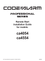
System Layout ........................................................................................... 21
2
ca4054 - 4554 Install rev A
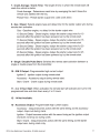
BEFORE YOU BEGIN
FOR AUTOMATIC TRANSMISSION VEHICLES ONLY.
PROFESSIONA L INSTALLATION
STRONGLY RECOMMENDE D
Roll down window to avoid locking keys in vehicle
during installation
Avoid mounting components or routing wires near
hot surfaces
Avoid mounting components or routing wires near
moving parts
Tape or loom wires under hood for protection and
appearance
Use a Digital Multi Meter for testing and verifying
circuits. DO NOT USE A TEST LIGHT, OR
"COMPUTER SAFE PROBE" as these can set off air
bags or damage vehicle computers.
Technical Support (800) 421-3209
..•..
2014 Voxx Electronics Corporation . All rights reserved.
or go to
http://avxtech1.com
3
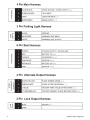
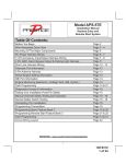
4 Pin Main Harness
BLUE/BLACK
START STATUS I ACTIVE OUTPUT ( - )
PURPLE/WHITE
TACH INPUT
GRAY
HOOD PIN INPUT (-)
BROWN/RED
BRAKE INPUT ( + )
3 Pin Parking Light Harness
(f)
Zl-I
a.. C)
C")
BLACK
GROUND
WHITE/RED
PARKING LIGHT INPUT
WHITE
PARKING LIGHT OUTPUT
-
_J
6 Pin Start Harness
PURPLE
STARTER OUTPUT- MOTOR SIDE
RED
BATTERY 12V ( +)
1-
ORANGE
ACCESSORY 1 ( + )
z
PINK/WHITE
IGNITION 2 ( + )
RED/WHITE
BATTERY 12V ( +)
PINK
IGNITION 1 ( + )
1-
0:::
<(
(f)
0:::
(0
4 Pin Alternate Output Harness
BLACK/YELLOW
PULSE DURING CRANK ( - )
GREEN/WHITE
PULSE AFTER SHUTDOWN ( - )
LT BLUE
FACTORY ARM I PULSE AFTER START (- )
LT GREEN/BLACK
FACTORY DISARM I PULSE BEFORE START ( - )
2 Pin Lock Output Harness
z~
-(.)
BLUE
N_J
OPEN
a..o
4
UNLOCK (-)
ca4054- 4554 Install rev A
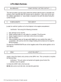
4 Pin Main Harness
1
BLUE/BLACK
START STATUS I ACTIVE OUTPUT ( - )
This wire provides a ground output when the remote start function is activated and
remains until 4 seconds after the remote start is shutdown. If this wire will be used
for multiple application's a 1 amp diode is required in-line with the stripe facing the
control module.
2
PURPLE/WHITE
TACH INPUT
Locate the vehicle's ignition coil or fuel injector in the engine compartment.
Verification: Test using the following procedure:
1.
2.
3.
4.
5.
Set voltmeter to AC VOLTS.
Attach positive lead of a volt meter to a constant 12-volt source.
Attach negative lead of a volt meter to the wire to be tested.
Start the engine.
Have someone press on the gas pedal slightly as you monitor the meter. If
connected to the correct wire, the voltage reading will increase as the engine's
RPM increases.
Connect the PURPLE/WHITE wire to the negative side of the vehicle ignition coil or
fuel injector.
3
GRAY
HOOD PIN INPUT (-)
Install a Hood Pin Switch and connect to the GRAY wire. This connection is required
for Remote Start.
Verification: This wire when connected will register ground when the
vehicle's hood is opened.
Connect the GRAY wire to the hood pin.
NOTE: Be sure to loom the wire, and seal the grommet.
2014 Voxx Electronics Corporation. All rights reserved.
5
4
BROWN/RED
BRAKE INPUT ( + )
Locate the vehicle's brake light wire at the brake pedal mounted switch. This
connection is required for Remote Start.
Verification: This wire registers positive voltage when the brake pedal is
pressed.
Connect the BROWN/RED wire to the vehicle's brake light wire.
3 Pin Parking Light Harness
1
BLACK
GROUND
Connect the BLACK wire to a solid chassis ground point using a ring terminal and
self tapping screw (not supplied). Scrape away paint from the grounding point to
ensure a good connection. The recommended grounding point is a metal surface in
the driver's side kick panel area.
NOTE: Do not ground the BLACK wire with any other vehicle components.
2
WHITE/RED
PARKING LIGHT INPUT
3
WHITE
PARKING LIGHT OUTPUT
Locate the parking light output wire at the vehicle's light switch.
Verification: This wire registers positive voltage when the parking lights are
turned on.
Positive switching Parking Lights:
Connect the WHITE/RED wire to a 15 Amp max fused battery source.
Connect the WHITE wire to the parking light output wire.
Negative switching Parking Lights:
Connect the WHITE/RED wire to a good chassis ground.
Connect the WHITE wire to the parking light output wire.
6
ca4054- 4554 Install rev A
6 Pin Start Harness
1
PURPLE
STARTER OUTPUT ( + )
Locate the vehicle starter wire.
Verification: This wire registers voltage only when the key is turned to the
START position.
Connect the PURPLE wire to the MOTOR SIDE of the vehicle starter wire.
2
RED
BATTERY 12V ( +)
Locate 1 of the vehicle's constant 12 Volt battery wires at the ignition switch.
Verification: This wire will register ( + ) voltage in all positions of the ignition
switch.
Connect the RED wire to the constant 12 Volt battery wire.
NOTE: Remove all fuses until all connections are made.
3
ORANGE
ACCESSORY 1 ( + )
Locate the vehicle's accessory wire at the ignition switch.
Verification: This wire registers voltage when the key is turned to ACC
(Accessory) and the ON (or RUN) position. The voltage drops out when the
key is turned to the START (or CRANK) position.
Connect the ORANGE wire to the vehicle's accessory wire.
4
PINK/WHITE
IGNITION 2 ( + )
Locate the vehicle's 2nd ignition wire at the ignition switch (if equipped).
Verification: This wire registers voltage when the key is turned to the ON (or
RUN) position, but not the ACC (Accessory) position. The voltage does not
drop out when the key is turned to the START (or CRANK) position.
Connect the PINK/WHITE wire to the vehicle's ignition 2 wire.
Programmable output: IGN, ACC, Start.
2014 Voxx Electronics Corporation. All rights reserved.
7
5
RED/WHITE
BATTERY 12V ( +)
Locate 1 of the vehicle's constant 12 Volt battery wires at the ignition switch.
Verification: This wire will register ( + ) voltage in all positions of the ignition
switch.
Connect the RED/WHITE wire to the constant 12 Volt battery wire.
NOTE: Remove all fuses until all connections are made.
6
PINK
IGNITION 1 ( +)
Locate the vehicle's ignition wire at the ignition switch.
Verification: This wire registers voltage when the key is turned to the ON (or
RUN) position. The voltage does not drop out when the key is turned to the
START (or CRANK) position.
Connect the PINK wire to the vehicle's Ignition wire.
This wire is also used for Ignition 1 Output.
4 Pin Alternate Output Harness
1
LT GREEN/BLACK
FACTORY DISARM I
PULSE BEFORE START ( - )
This wire will supply a ( - ) 200mA pulse both upon disarming the system and when
the remote start feature is activated. Locate the factory perimeter alarm disarm wire
from the key cylinder inside the drivers door.
Verification: This wire registers ground if the key is turned to the unlock
position in the driver's door cylinder.
This output is configurable in option programming.
2
LT BLUE
FACTORY ARM I
PULSE AFTER START ( - )
This wire will supply a (-) 200mA pulse upon successful completion of the remote
start activation sequence and is typically used to re-lock the vehicle's doors upon
remote start if necessary.
This output is configurable in option programming.
8
ca4054 - 4554 Install rev A
3
GREEN/WHITE
PULSE AFTER SHUTDOWN ( - )
This wire will supply a (-) 200mA pulse after the remote start shuts down. This
is typically used to re-lock the vehicle's doors if they unlock upon remote start
shutdown. It can also be used to pulse a door pin-switch wire to prevent the vehicle's
accessories from remaining on after remote start shutdown.
This output is configurable in option programming.
4
BLACK/YELLOW
PULSE DURING CRANK (-)
Locate the vehicle's second starter (crank) wire at the ignition switch. (if equipped)
Verification: This wire registers voltage only in the start (crank) position of
the ignition switch.
This wire will supply a ( - ) 200mA output and can be configured in option
programming.
2 Pin Lock Output Harness
1
BLUE
UNLOCK (-)
The door unlock output wire provides an output only while the remote start feature is
active.
2014 Voxx Electronics Corporation. All rights reserved.
9
Additional Ports
Antenna I LED I Programming Port
Mount the supplied antenna/receiver to a clear spot on the vehicle's windshield that
will not block the driver's vision. A good location is usually high on the windshield
near the rear view mirror. Be careful not to mount the antenna/receiver on any
metallic window film, as this will effect system range. Route the antenna/receiver
cable to the control module and plug into the antenna port.
Data Bus Interface Port
This 4 pin port is used for Flashlogic Door Lock and Transponder Databus Interfaces
to communicate with the vehicle's Databus. When using the OBI port to control the
Flashlogic Door Lock and Transponder Interface modules the following options may
be available. Please refer to the 020 (Data to Data) function list available per vehicle
on the tech service web site.
Tach Input
Brake Safety Shut Down
Trunk/Hatch Open
Diesel Glow Plug Input
Door Lock Control
Passlock I Passkey Interface (GM Only)
Dome Light Supervision
Transponder Interface Activation
Factory Alarm Arm I Disarm
Manual Arm I Disarm Inputs (factory keyless
controls system)
Telematic Interface Port - CA4554 ONLY
This 4 pin port is used for Telematic Interface accessories, such as Car Connection
Pro, which can control some of the following features.
10
Door Unlock Control
Trunk Release
Sliding Doors
AUX Output
Car Find
Remote Start
ca4054- 4554 Install rev A
Set Up & Programming
Transmitter Programming - Feature Bank 1
1.
Turn the ignition ON.
2.
Press and hold the valet/override button.
3.
Within 10 seconds the parking lights will flash (3) three times.
4.
Press 1 button of each transmitter you wish to program.
5.
The system will respond with 1 light flash for each accepted transmitter.
6.
Pressing the override button at anytime during programming will advance to
the next bank.
NOTE: The system will exit transmitter programming after 15 seconds of inactivity.
NOTE: This system has 1 button programming which programs all channels of the
system.
NOTE: The system will hold up to 4 transmitters in memory, programming a 5th
transmitter will erase the oldest transmitter in memory.
NOTE: This system has PTN- Programmed Transmitter Notification. Each time the
ignition is turned ON, the LED will flash the number of transmitters programmed to the
system.
Manual Feature Programming - Feature Bank 2 - 5
1.
Turn the ignition ON.
2.
Press and hold the valet/override button.
3.
Within 10 seconds the parking lights will flash (3) three times.
4.
Use the valet/override button to advance through each option bank. For
feature programming advance to Feature Bank 2, 3, 4 or 5, which is (4)
four, (5) five, (6) six and (7) seven parking light flashes.
5.
Use the transmitter 0 button to scroll through the selections in each
feature bank, the parking lights will flash to match the feature number.
6.
Press the BRAKE to change the desired feature. The LED will flash
indicating the changed feature.
NOTE: The system will remain in feature programming mode as long as the ignition
is on, there is no time limit. To exit programming turn the IGNITION OFF.
2014 Voxx Electronics Corporation. All rights reserved.
11
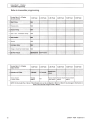
Feature Bank 1 - 3 Flashes
Transmitter Programming
Refer to transmitter programming.
Feature Bank 2 - 4 Flashes
Feature Bank 3- 5 Flashes
Factory Disarm
Lt Green I Black
1 LED Flash
4 LED Flash
1 LED Flash
Factory
Disarm
NIA
Factory Disarm Factory Disarm Factory Disarm
500mS
350mS
I Start Status
2
NOTE: On this model the Lt Green I Black Output wire can be configured in Bank 3 or Bank 5. Any changes to this feature in
Bank 5 will override changes made in Bank 3.
12
ca4054- 4554 Install rev A
Feature Bank 4- 6 Flashes
Feature Bank 5 - 7 Chirps
4 Pin Alternate Output Control
NOTE: On this model the Lt Green I Black Output wire can be configured in Bank 3 or Bank 5. Any changes to this feature in
Bank 5 will override changes made in Bank 3.
4
Black I Yellow Output
Pulse During
Crank
Ground While
Running
Ignition
Accessory
Ground While
Running
Ignition
Accessory
2014 Voxx Electronics Corporation. All rights reserved.
Pulse During
Crank
13
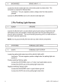
Tach Programming
The unit will not operate unless tach is programmed or tach less option is
turned ON. If an attempt is made to start the vehicle via the remote start without first
programming tach, the unit will flash the parking lights 7 times indicating tach has not
been learned and stored. If the tach rate is not properly programmed to the specific
vehicle, the unit may not realize that the vehicle is running in certain instances and
reengage the starter motor.
The Remote Start unit will learn the tach rate of most vehicle's single coil, multiple coil
packs, or single injector. To learn tach:
1.
Turn the ignition key to the ON position.
2.
Press and release the valet/override button 3 times.
3.
Immediately turn the ignition key OFF.
4.
Press and hold the valet/override button, then start the vehicle using
the key.
5.
When the unit senses the tach signal, the parking lights will begin to
flash.
6.
Allow the vehicle to settle to a normal idle speed.
Release the valet/program push-button switch. The parking lights will
stay on solid indicating that the learned tach signal is stored and the
unit has exited tach learn mode.
7.
NOTE: If the unit fails to learn tach rate due to an improper tach connection or a
poor tach source, the parking lights will not flash. To correct this situation, locate and
connect the PURPLE/WHITE wire to the proper tach signal, and then repeat the tach
learn routine.
Smart Tachless Mode
Smart Tach less Mode is available only if a tach signal has never been learned to the
system and when activated will automatically change the Tach Mode feature in option
programming to Tach less without the need to enter the feature programming mode.
14
1.
Activate the remote start. The parking lights should begin flashing 7
times indicating no tach signal has been learned.
2.
Within the 7 flash time period, press and hold the
3.
One extended parking light flash (1.5 seconds) will indicate the
system is now in tachless mode.
0
button.
ca4054 - 4554 Install rev A
Feature Descriptions
Feature Bank 2- Security
1 - 8 Not Available.
9- OBI Port Protocol: Determines the protocol type in which the OBI port uses to
interface with external modules.
OBI Protocol
ADS Protocol
Feature Bank 3 - Output Control
1 -Extended Lock Pulse: Controls the timing of the BLUE unlock output wire.
1 Second - Single 1 second unlock pulse.
3.5 Seconds - Single 3.5 second unlock pulse.
Double Pulse Unlock - Double 1 second unlock pulse.
2 - Factory Disarm - Lt Green/Black Output: Controls the timing of the LT. GREEN/
BLACK factory disarm wire on the 6 pin output harness only and does not change
the output of the factory disarm wire on the 4 pin alternate output harness.
Factory Disarm - Single 1 second pulse with unlock and remote start
activation.
N/A- Setting not available on this model.
Start Status- Continuous (-)output during the remote start cycle.
Factory Disarm - Single 350mS second pulse with unlock and remote start
activation.
Factory Disarm - Single 500mS second pulse with unlock and remote start
activation.
NOTE : 4 & 5 series product - On this model the Lt Green I Black Output wire can be
configured in Bank 3 or Bank 5. Any changes to this feature in Bank 5 will override
changes made in Bank 3.
2014 Voxx Electronics Corporation. All rights reserved.
15
Feature Bank 4 - Remote Start Control
1 - Not Available.
2 - Run Time: Controls the time in minutes that the vehicle will stay running under
control of the remote start until the system times out. The system may also be shut
down at any time by use of the transmitter or system shutdowns.
3- Running Lights: Controls the WHITE parking light output wire during remote
start.
Steady - Parking lights constant during the remote start cycle.
Flashing - Parking lights flash at a slow pace during the remote start cycle.
4 - Tach Mode: Determines how the system monitors the engine running during
remote start.
Tach - Hard wired directly to the tach wire of the vehicle to monitor AC
voltage.
Tach less (Crank Average/Voltage) - Determines crank time by averaging
the last 8 times the vehicle was started with the key and then monitors the
change in voltage after remote start.
Hybrid (Crank Average I No Voltage) - Determines crank time by averaging
the last 8 times the vehicle was started with the key.
DBI Port - Monitors the vehicle's tach rate through an interface module
connected to the DBI port.
5- Voltage Level: The voltage variance for remote start when set to tachless. (see
tach mode)
HIGH- The variance in battery voltage from before the remote start
is activated to after the engine is running must be greater than 0.5 volts.
LOW - The variance in battery voltage from before the remote start
is activated to after the engine is running may be less than 0.5 volts.
6 - Crank Time: Preset output times for the PURPLE starter wire.
1 Second
16
0.8 Seconds
1.5 Seconds
2 Seconds
4 Seconds
ca4054- 4554 Install rev A
7 - Crank Average I Crank Time: The length of time in which the remote start will
crank the vehicle's starter.
Crank Average - Determines crank time by averaging the last 8 times the
vehicle was started with the key.
Preset Time - Preset starter output time. (see crank time)
8 - Gas I Diesel: Selects engine type and delay time for the starter output wire during
remote start activation.
Gas- Gasoline engine, no delay for the starter output wire.
10 Second Delay - Diesel engine, delays the starter output wire for 10
seconds after the ignition has been powered up by the remote start.
15 Second Delay - Diesel engine, delays the starter output wire for 15
seconds after the ignition has been powered up by the remote start.
20 Second Delay - Diesel engine, delays the starter output wire for 20
seconds after the ignition has been powered up by the remote start.
45 Second Delay - Diesel engine, delays the starter output wire for 45
seconds after the ignition has been powered up by the remote start.
9 - Single I Double Pulse Start: Switches the remote start activation between a
single or double press from the transmitter.
10 - IGN 2 Output: Programmable high current output.
Ignition 2 - Ignition output during remote start.
Accessory- Accessory output during remote start.
Start I Crank - Crank output during remote start.
11 - 2 or 3 Hour Start: When activated, the remote start will activate and run for the
programmed time and shut down every 2 or 3 hours.
12 - 14 Not Available.
15 -Accessory Output: Programmable high current output.
Accessory- Output becomes active with the same timing as the accessory
output, drops out during crank.
Ignition - Output becomes active with the same timing as the ignition output
and does not drop out during crank.
Start I Crank - Output becomes active with the same timing as the starter
output wire, during crank only.
2014 Voxx Electronics Corporation. All rights reserved.
17
Feature Bank 5 - 4 Pin Alternate Output Control
1 - Lt Green/Black Output : Controls the LT GREEN/BLACK output activation type
and timing.
Pulse before Start I During Unlock - 1 second pulse when remote start is
activated. Also a 1 second pulse when unlock is pressed.
Ground While Running - Continuous output for the entire remote start
sequence until after the vehicle shuts down.
Ignition - Output becomes active with the same timing as the ignition output
and does not drop out during crank.
Accessory - Output becomes active with the same timing as the accessory
output, drops out during crank.
Pulse During Crank - Output becomes active with the same timing as the
starter output wire, during crank only.
2 - Lt Blue Output : Controls the LT BLUE output activation type and timing.
Pulse After Start I During Lock - 1 second pulse after the remote start
sequence and has confirmed the vehicle is running.
Ground While Running - Continuous output for the entire remote start
sequence until after the vehicle shuts down.
Ignition - Output becomes active with the same timing as the ignition output
and does not drop out during crank.
Accessory - Output becomes active with the same timing as the accessory
output, drops out during crank.
Pulse During Crank - Output becomes active with the same timing as the
starter output wire, during crank only.
3- Green/White Output: Controls the GREEN/WHITE output activation type and
timing.
Pulse After Shutdown - 2 second pulse after the remote start has
shutdown.
Ground While Running - Continuous output for the entire remote start
sequence until after the vehicle shuts down.
Ignition - Output becomes active with the same timing as the ignition output
and does not drop out during crank.
Accessory - Output becomes active with the same timing as the accessory
output, drops out during crank.
Pulse During Crank - Output becomes active with the same timing as the
starter output wire, during crank only.
18
ca4054- 4554 Install rev A
4 - Black/Yellow Output : Controls the BLACK/YELLOW output activation type and
timing.
Pulse During Crank - Output becomes active with the same timing as the
starter output wire, during crank only.
Ground While Running - Continuous output for the entire remote start
sequence until after the vehicle shuts down.
Ignition - Output becomes active with the same timing as the ignition output
and does not drop out during crank.
Accessory - Output becomes active with the same timing as the accessory
output, drops out during crank.
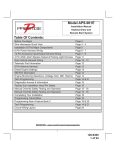
Transmitter Button Functions
2014 Voxx Electronics Corporation. All rights reserved .
19
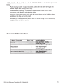
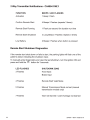
2 Way Transmitter Notifications- CA4554 ONLY
FUNCTION
BEEPS I LED FLASHES
Activation
1 Beep I Flash
Confirm Remote Start
4 Beeps I Flashes (repeats 3 times)
Remote Start Running
1 Flash per second for duration run time
Remote Start Shutdown
3 Long Beeps I Flashes (repeats 3 times)
Low Battery
2 Beeps I Flashes when button is pressed
Remote Start Shutdown Diagnostics
If the remote start shuts down or fails to start, the parking lights will flash one of the
patterns below indicating the shutdown input.
To manually enter diagnostics and view the last shutdown, turn the ignition ON and
press and hold the 0 button for 3 seconds.
LED FLASHES
SHUTDOWN ZONE
3 Flashes
Hood Input
Brake Input
20
4 Flashes
Remote Start Valet Mode
5 Flashes
Manual Transmission Mode not set (manual
transmission models only)
7 Flashes
Tach not learned I Crank Average not learned
ca4054 - 4554 Install rev A
N
0
.......
#4120104
~
~
X
BLUE
OPEN
UNLOCK (-)
BLACK/YELLOW
GREEN/WHITE
LT BLUE
LT GREEN/BLACK
PULSE DURING CRANK (-)
PULSE AFTER SHUTDOWN ( - )
FACTORY ARM I PULSE AFTER START (-)
FACTORY DISARM I PULSE BEFORE START ( - )
X
m
ro
n.
a
# 4120102
::l
;::;·
(/J
0
0....,
'0
0
....,
D
~
6'
::l
#4120103
~
....,
(Q'
~
Ui
co
(/J
CD
<
CD
a.
E~
n:~
s~
~~
IU
~~
l[)l[)
0 l[)
I
BLACK
WHITE/RED
WHITE
GROUND
PARKING LIGHT INPUT
PARKING LIGHT OUTPUT
BLUE/BLACK
PURPLE/WHITE
GRAY
BROWN/RED
START STATUS I ACTIVE OUTPUT (-)
TACH INPUT
HOOD INPUT (-)
BRAKE INPUT(+)
~~
~~
0('1')
NN
l[) l[)
00
coco
# 4120105
-------------------
D
('I') ('I')
"<t"<t
~~
0
0
u
OBI PORT
# 4180025 (CA4054) ,,
# 4120192
0
I
...
ANTENNA
LED
VALET
TELEMATIC PORT- CA4554 ONLY
# 4120110
N
.......
PURPLE
RED
ORANGE
PINK/WHITE
RED/WHITE
PINK
STARTER OUTPUT- MOTOR SIDE ( + )
BATTERY 12V ( + )
ACCESSORY 1 ( + )
IGNITION 2 ( +)
BATTERY 12V ( + )
IGNITION 1 ( + )
22
ca4054- 4554 Install rev A
2014 Voxx Electronics Corporation. All rights reserved.
23
Voxx Electronics Corporation.
Customer Service 1-800-421-3209
WWW.CODE-ALARM.COM
FCC COMPLIANCE
This device complies with Part 15 of the FCC rules and with RSS-21 0 of
Industry Canada. Operation is subject to the following two conditions:
1. This device may not cause harmful interference, and
2. This device must accept any interference received, including any interference that
may cause undesired operation.
Warning!
Changes or modifications not expressly approved by the party responsible for
compliance could void the user's authority to operate the equipment.
24
R41 0-192-670
ca4054 - 4554 Install rev A
CCJCc:~IA~m
Remote Start System
IMPORTANT NOTE: The operation of the Security and Convenience System as described in this manual is
applicable to most vehicles. However, due to the configuration of some vehicles, some functions AND/OR
SAFETY PRECAUTIONS may not apply. Please see your installing dealer for more information.
2014 Voxx Electronics Corporation. All rights reserved.
4280597
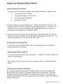
Using Your Remote Vehicle Starter
Remote Starting Your Vehicle
The system WILL NOT start the vehicle if any one of the following
1.
The vehicle's hood is opened.
2.
The gear shift selector is not in Park.
3.
The brake pedal is depressed.
4.
Valet Mode is active.
situations exist:
1. To start the vehicle, press and release the 0 button 2 times within 2 seconds. The
vehicle will start and remain running for the pre-programmed 5, 10, 15, 20, 45 or 60
minute run cycle. As a visual indication, the parking lights will flash or remain on
depending on the setting by your installation center.
2. When you arrive at the vehicle, turn the ignition key to the ON position (Do not try to
restart the vehicle), then step on the brake pedal to disengage the remote start. The
vehicle will continue to run, but now on it's own power.
Shutting Down the Remote Start
To shut down the remote start feature from the transmitter press and release the if)
button 2 times within 2 seconds.
Unlocking the Vehicle (optional)
To unlock the vehicle's doors press and hold the 0 button for 3 seconds anytime the
vehicle is remote started.
Note: Additional parts and/or labor may be necessary, see your installing dealer for
details.
Programmed Transmitter Notification
As a security precaution each time the vehicle's ignition is turn on the status LED
light with flash the number of transmitters programmed into the system. This helps
to identify unauthorized transmitters from accessing your vehicle. If you believe an
unauthorized transmitter has been programmed to your system, contact your installing
dealer for assistance.
2
ca4054 & 4554 Owners revA
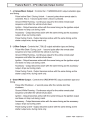
Operating the 2 I 3 Hour Start Up Timer Mode
The system has the ability to start the vehicle every 2 or 3 hours for a 48 hour period.
This feature is especially useful in cold climates where the only means to keep the
engine and engine fluids warm is to periodically start the engine. The default setting is
3 hour, selection between 2 or 3 hour is made in option programming.
WARNING!
Be certain that the vehicle is outdoors before using this or any remote starting
device. A running engine produces dangerous carbon monoxide fumes which can be
harmful or fatal if prolonged exposure occurs. DO NOT remote start the vehicle if it is
garaged.
To begin the 2 I 3 hour start up timer mode:
1.
Turn the vehicle's ignition ON then OFF.
2.
Press and hold the valet button.
3.
Press the 0 button 4 times, the system will;
a. When set for 3 Hour (default)- flash the parking lights 4 times.
b. When set for 2 Hour - flash the parking lights 2 times.
4.
Release the valet button.
To exit the 2/3 hour start up timer mode:
1.
Turn the vehicle's Ignition ON.
OR
1.
Activate the remote vehicle start feature using the remote control.
Using the ~~Quick-stop" Feature
If you want to make a short stop and keep your vehicle running (to keep the interior
warm or cool), the quick-stop feature allows you to do this while keeping your vehicle
secure and your keys with you.
To engage quick stop:
1.
Stop the vehicle and place the transmission in PARK.
2.
With your foot off the brake pedal, press and release the 0 button 2
times within 2 seconds. The LED will flash 3 times to confirm quick
stop is entered.
3.
Remove the keys from the ignition and exit the vehicle. Lock the
vehicle's doors if desired.
Note: Do not leave children or animals unattended in the vehicle when using the
quick-stop feature.
2014 Voxx Electronics Corporation . All rights reserved.
3
Valet Mode
Valet Mode is used to disable the system from remote starting. To enter
or exit valet mode simply follow the 4 steps outlined below:
1.
Turn the vehicle's ignition ON.
2.
Push and hold the programming/valet button.
3.
The LED will turn on solid when valet mode is active
4.
Release the programming/valet button.
Transmitter Button Functions
2 Way Transmitter Notifications - ca4554 Only
4
FUNCTION
BEEPS I LED FLASHES
Activation
1 Beep I Flash
Confirm Remote Start
4 Beeps I Flashes (repeats 3 times)
Remote Start Running
1 Flash per 3 seconds for duration run time
Remote Start Shutdown
3 Long Beep I Long Flashes (repeats 3 times)
Low Battery
2 Beeps I Flashes when button is pressed
ca4054 & 4554 Owners revA
Replacing Remote Control Batteries
1 Way Remote Control, CATX1 B:
The batteries (model CR2016) inside each remote control should last approximately 1
year under normal use. When the batteries become weak you will notice the remote
control range (the distance from the vehicle the remote control will work) deteriorate
and the small LED on the remote control will dim. To replace the remote control
batteries:
1.
Unsnap and disassemble the halves of the remote control.
2.
Remove the old batteries, observing the +/- symbols on the batteries
and replace with new CR2016 batteries.
3.
Reassemble the halves of the remote control.
4.
Test operation of the remote control.
2 Way Remote Control, CATX1TW- ca4554 Only:
The battery (model CR2032) inside each remote control should last approximately 10
months under normal use. When the battery become weak you will notice the remote
control range (the distance from the vehicle the remote control will work) deteriorate
and the small LED on the remote control will dim. To replace the remote control
battery:
1.
Remove 3 screws and disassemble the halves of the remote control.
2.
Remove the old battery, observing the +/- symbols on the battery
and replace with a new CR2032 battery.
3.
Reassemble the halves of the remote control and install the 3 screws.
4.
Test operation of the remote control.
2014 Voxx Electronics Corporation. All rights reserved.
5
Code Systems, Inc. Limited Lifetime Warranty
Code Systems Inc. ("CODE") warrants to the ORIGINAL PURCHASER of this CODE vehicle security
product (the "Product"), purchased from an authorized CODE dealer, that (except as provided below)
should this Product under normal use and conditions, be proven defective in material or workmanship
DURING THE LIFETIME OF THE VEHICLE IN WHICH IT WAS ORIGINALLY INSTALLED, such
defect(s) will be repaired or replaced (at CODE's option) without charge for parts directly related to
repairs of the defect(s).
Switches, indicator lights, and transmitter cases are similarly warranted to the original purchaser for
a period of one (1) year from the date of purchase of the Product.
CODE accessories, sold separately, are covered by the applicable warranty accompanying the
accessory.
This warranty is non-transferable, non-assignable and is voided when: (1) the Product is removed from
the vehicle in which it was originally installed; or (2) the vehicle in which the Product was originally
installed is transferred to another party.
This warranty does not apply to any product damaged by accident, physical or electrical abuse, improper installation, alteration, or use contrary to its intended function, fire, flood, or other natural acts.
In order for the Product to be repaired or replaced under the terms of this warranty, the defective
Product must be returned to an authorized CODE dealer and accompanied by a copy of the retail
sales receipt. The date of purchase and year, make and model of the vehicle in which the Product
was originally installed must be clearly indicated on the sales receipt.
This warranty is exclusive and CODE MAKES NO OTHER WARRANTIES EXPRESSED OR IMPLIED.
ANY IMPLIED WARRANTIES, INCLUDING ANY IMPLIED WARRANTY OF MERCHANTABILITY
AND FITNESS FOR A PARTICULAR PURPOSE, SHALL BE LIMITED TO THE DURATION OF THIS
WRITTEN WARRANTY. IN NO CASE SHALL CODE BE LIABLE FOR ANY CONSEQUENTIAL OR
INCIDENTAL DAMAGES FOR BREACH OF THIS OR ANY OTHER WARRANTY, EXPRESS OR
IMPLIED, WHATSOEVER.
CODE does not warrant that the Product cannot be compromised or circumvented. THE EXTENT OF
CODE'S LIABILITY UNDER THIS WARRANTY IS LIMITED TO THE REPAIR OR REPLACEMENT
PROVIDED ABOVE AND, IN NO EVENT SHALL CODE'S LIABILITY EXCEED THE PURCHASE
PRICE PAID BY THE ORIGINAL PURCHASER OF THE PRODUCT WITHOUT INSTALLATION
LABOR.
Some states do not allow the exclusion or limitation of incidental or consequential damages, so the
above limitation may not apply to you. This warranty gives you specific legal rights and you may also
have other rights which vary from state to state
6
ca4054 & 4554 Owners revA
This product is covered by one or mote of the following U.S. Patents; Other Patents pending.
0407,034,0580,160,5,132.660. 51157.375~ 5.193,141. 5.245.694. 5.315.285. 5.334.969
5,349,931~
5.,357.560, 5.381.128•.5,412.371. 5,467.070. 5.469.141,
5.469~151. 5~506.568
51532.670. 5.534.845. 5.563,576, 5~583.600. 5.572.185. 5.602.535, 5.614,883. 5t617.819
5,646.591'
5~650,774.
5,656*868, 5,673.017, 5t656,997.• 5,712,638, 5,783.988, 5t783,989
5.798,711. 5.805.056. 5.8191588* 5,8.28,316. 5.838.255. 5.850.173. 5.850.174. 5.855.050
5.872.519, 5t898,391. 5~900,806. 5t905,431. 5'!907,195. 5,914.667. 5.945+936. 51952.933
5.990. 786. 6.028. 732. 8.028.505, 6.040.636. 6.043. 734. 8.087.996. 6.093.979. 6.140,914
6, 184.n9. 6.218.740, 6.259,169~ 6,285.296, 6.288.635. &.317,034, 6.452,483. 6.452.484
6.462.648, 6.573.838, 6.697.719, 6,700.479. 6,781,507, 6,828.901., 6,982,631. 7,030.739
7,069.1271 7.0951314,7,102.515, 7,135.962, 7,142.0971 7,191,053,.7.243t007, 7,248.150
7.332~998. 7,443.285, 7.463,135,7A83~783. 7,519,400. 7,532,959, 7.616,.099. 7.646.285
7 ~653.•463. 7~962.2601 8.380,430.
2014 Voxx Electronics Corporation. All rights reserved.
7
Voxx Electronics Corporation.
Customer Service 1-800-421-3209
WWW.CODE-ALARM.COM
FCC COMPLIANCE
This device complies with Part 15 of the FCC rules and with RSS-21 0 of
Industry Canada. Operation is subject to the following two conditions:
1. This device may not cause harmful interference, and
2. This device must accept any interference received, including any interference that
may cause undesired operation.
Warning!
Changes or modifications not expressly approved by the party responsible for
compliance could void the user's authority to operate the equipment.
8
R41 0-192-680
ca4054 & 4554 Owners revA
WARNING
THIS VEHICLE IS EQUIPPED WITH A REMOTE
CONTROLL ED CAR STARTER
BEFORE SERVICING THIS VEHICLE, REMOVE THE MAIN
POWER FUSE (RED WIRE) TO THE CAR STARTER OR
DISCONNE CT THE VEHICLE BATTERY.
LBL0675