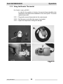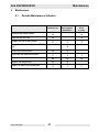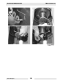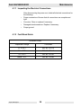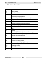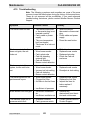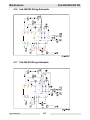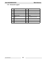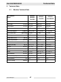
1
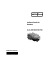
0170893en 006 0809 Indirect-fired Air Heaters Cub 200/300/300 HD OPERATOR’S MANUAL 0 1 7 0 8 9 3 E N Foreword 1 Foreword WARNING CALIFORNIA Proposition 65 Warning: Engine exhaust, some of its constituents, and certain vehicle components, contain or emit chemicals known to the State of California to cause cancer and birth defects or other reproductive harm. This manual provides information and procedures to safely operate and maintain this Wacker Neuson model. For your own safety and protection from injury, carefully read, understand and observe the safety instructions described in this manual. Keep this manual or a copy of it with the machine. If you lose this manual or need an additional copy, please contact Wacker Neuson Corporation. This machine is built with user safety in mind; however, it can present hazards if improperly operated and serviced. Follow operating instructions carefully! If you have questions about operating or servicing this equipment, please contact Wacker Neuson Corporation. The information contained in this manual was based on machines in production at the time of publication. Wacker Neuson Corporation reserves the right to change any portion of this information without notice. All rights, especially copying and distribution rights, are reserved. Copyright 2009 by Wacker Neuson Corporation. No part of this publication may be reproduced in any form or by any means, electronic or mechanical, including photocopying, without express written permission from Wacker Neuson Corporation. Any type of reproduction or distribution not authorized by Wacker Neuson Corporation represents an infringement of valid copyrights and will be prosecuted. We expressly reserve the right to make technical modifications, even without due notice, which aim at improving our machines or their safety standards. wcghi_tx000001gb diesel.fm 3 Foreword Notes: wcghi_tx000001gb diesel.fm 4 Table of Contents 1. Foreword 3 2. Safety Information 7 2.1 2.2 2.3 2.4 2.5 3. Operation 3.1 3.2 3.3 3.4 3.5 3.6 3.7 3.8 3.9 3.10 3.11 3.12 3.13 4. Operating Safety .................................................................................. 7 Operator Safety while using Combustion Burners ............................... 8 Service Safety ...................................................................................... 8 Label Locations .................................................................................. 10 Label Descriptions .............................................................................. 11 15 System Description ............................................................................ 15 Installing the Lift Brackets .................................................................. 15 System Component Locations ........................................................... 16 Mounting the Handle and Base Assembly ......................................... 17 Machine Location ............................................................................... 18 Suggested Venting ............................................................................. 18 Connecting Power to the Machine ..................................................... 20 Preliminary Checks ............................................................................ 20 Control Panel ...................................................................................... 21 Starting the Machine .......................................................................... 22 Starting the Machine in (Extreme) Cold Weather ............................... 23 Shutting Down the Machine ............................................................... 24 Using the Remote Thermostat ........................................................... 25 Maintenance 4.1 4.2 4.3 4.4 4.5 4.6 4.7 4.8 4.9 4.10 27 Periodic Maintenance Schedule ......................................................... 27 Removing and Installing the Burner Assembly ................................... 28 Replacing the Burner Nozzle .............................................................. 30 Replacing the Fuel Filter .................................................................... 31 Inspecting and Aligning the Burner Electrodes .................................. 32 Inspecting and Cleaning the Cadmium (CAD) Cell ............................ 33 Checking and Adjusting the Fuel Pressure ........................................ 34 Cleaning the Fan Blades and Motor ................................................... 36 Cleaning the Interior Shell .................................................................. 37 Inspecting the Flame Head ................................................................ 38 ghi_bo0170893en_006TOC.fm 5 Table of Contents 4.11 4.12 4.13 4.14 4.15 4.16 4.17 4.18 5. Inspecting the Electrical Connections .................................................39 Fuel Blend Guide .................................................................................39 Transporting ........................................................................................40 List of Abbreviations ............................................................................41 Troubleshooting ...................................................................................42 Cub 200/300 Wiring Schematic ...........................................................44 Cub 300 HD Wiring Schematic ............................................................44 Schematic Legend ...............................................................................45 Technical Data 5.1 47 Machine Technical Data ......................................................................47 ghi_bo0170893en_006TOC.fm 6 Cub 200/300/300 HD 2 Safety Information Safety Information This manual contains DANGER, WARNING, CAUTION, NOTICE, and NOTE callouts which must be followed to reduce the possibility of personal injury, damage to the equipment, or improper service. This is the safety alert symbol. It is used to alert you to potential personal injury hazards. Obey all safety messages that follow this symbol to avoid possible injury or death. DANGER indicates a hazardous situation which, if not avoided, will result in death or serious injury. DANGER WARNING indicates a hazardous situation which, if not avoided, could result in death or serious injury. WARNING CAUTION indicates a hazardous situation which, if not avoided, could result in minor or moderate injury. CAUTION NOTICE: Used without the safety alert symbol, NOTICE indicates a situation which, if not avoided, could result in property damage. Note: Contains additional information important to a procedure. 2.1 Operating Safety WARNING Familiarity and proper training are required for the safe operation of equipment! Equipment operated improperly or by untrained personnel can be dangerous! Read the operating instructions contained in this manual and familiarize yourself with the location and proper use of all controls. Inexperienced operators should receive instruction from someone familiar with the equipment before being allowed to operate the machine. 2.1.1 Be sure the machine is on a firm, level surface and will not tip, roll, slide, or fall while operating. 2.1.2 NEVER start a machine in need of repair. wcghi_si000212gb.fm 7 Safety Information Cub 200/300/300 HD 2.1.3 Keep unauthorized personnel, children, and pets away from the machine. 2.1.4 Always operate machine with all safety devices and guards in place and in working order. Do not modify or defeat safety devices. Do not operate machine if any safety devices or guards are missing or inoperative. 2.1.5 NEVER run the machine indoors or in an enclosed area unless adequate ventilation, through such items as exhaust fans or hoses, is provided and if local and national codes permit. Exhaust from the burner contains poisonous carbon monoxide gas. Exposure to carbon monoxide can cause loss of consciousness and may lead to death. 2.1.6 Do not smoke while operating the machine. 2.1.7 NEVER run the machine in areas that contain flammable objects, fuels, or products that produce flammable vapors. 2.1.8 NEVER connect ductwork between the exhaust outlet port and the supply air inlet port. 2.1.9 NEVER block the air inlet or outlet. 2.1.10 The installation of this machine must be in accordance with the regulations put forth by all governing bodies having jurisdiction including the Canadian Standard B139. 2.2 Operator Safety while using Combustion Burners 2.2.1 Refill the fuel tank in a well-ventilated area. 2.2.2 Replace the fuel tank cap after refueling. 2.2.3 DO NOT spill fuel when refueling the machine. Clean up spilled fuel immediately. 2.2.4 DO NOT smoke when refueling machine. 2.2.5 DO NOT refuel a hot or running machine. 2.2.6 The machine must be installed by qualified personnel who have read and understand all supplied manuals and instructions. 2.2.7 When operating the machine indoors, install a carbon monoxide detector in the work area according to the detector manufacturer’s instructions. 2.2.8 2.3 Service Safety WARNING wcghi_si000212gb.fm HIGH VOLTAGE! This unit uses high voltage circuits capable of causing serious injury or death. Only a qualified electrician should troubleshoot or repair electrical problems occurring with this equipment. 8 Cub 200/300/300 HD Safety Information 2.3.1 ALWAYS replace the safety devices and guards after repairs and maintenance. 2.3.2 Keep the machine clean and labels legible. Replace all missing and hard-to-read labels. Labels provide important operating instructions and warn of dangers and hazards. 2.3.3 ALWAYS make sure slings, chains, hooks, ramps, jacks, and other types of lifting devices are attached securely and have enough weightbearing capacity to lift or hold the machine safely. Always remain aware of the location of other people in the area when lifting the machine. 2.3.4 ALWAYS replace or repair electrical components with components that are identical in rating and performance as the original component. 2.3.5 Do not use gasoline or other types of fuels or flammable solvents to clean parts, especially in enclosed areas. Fumes from fuels and solvents can become explosive. 2.3.6 Always wear protective epuipment when servicing the machine. Some machine components may be hot and contain hot fluids. 2.3.7 Notes: wcghi_si000212gb.fm 9 Safety Information 2.4 Cub 200/300/300 HD Label Locations wcghi_si000212gb.fm 10 Cub 200/300/300 HD 2.5 Ref. Safety Information Label Descriptions Label Label Text 1 Danger! Hazardous voltage. Do not operate without this cover in place. Disconnect and lock out power source before opening panel. Could cause severe injury or death. 2 Warning: Blower can automatically start which can cause serious injury. Disconnect power source before servicing. 3 WARNING Warning: Blower can automatically start which can cause serious injury. Disconnect power source before servicing. 177370 WARNUNG ADVERTENCIA AVERTIS SEMENT wcghi_si000212gb.fm 11 Safety Information Ref. Label Cub 200/300/300 HD Label Text 4 Using a heater indoors can kill you in minutes. Heater exhaust contains carbon monoxide. This is a poison you cannot see or smell. During indoor operation, vent exhaust gas outdoors. Refer to Operator's Manual. 5 Warning: Electric shock hazard. Disconnect power before servicing. Read Operator’s Manual. 6 Danger: To avoid injury from moving parts, shut off the equipment before removing this cover. DANGER TO AVOID INJURY FROM MOVING PARTS, SHUT OFF THE EQUIPMENT BEFORE REMOVING THIS COVER. 7 CAUTION D DIESEL VORSICHT PRECAUCION PRECAUCION Hot surface hazard! 8 9 Caution: This machine uses diesel fuel. CAUTION Caution: Lift point. Attach lifting device in this location. VORSICHT PRECAUCION PRECAUTION wcghi_si000212gb.fm 12 Cub 200/300/300 HD Ref. Label Safety Information Label Text 10 Diesel fuel blend guide. This label indicates the recommended fuel blending values for diesel fuel usage. 11 Tie-down point. 12 Machine rating label: This label indicates rating information for the machine. 13 Weight/mass label: This label indicates the total weight of the machine, including the trailer and a full fuel tank. 14 Model and serial number label: This label shows the model name and the serial number for the heat exchanger on your machine. wcghi_si000212gb.fm 13 Safety Information Ref. Label Cub 200/300/300 HD Label Text 15 A nameplate listing the model number, item number, revision number, and serial number is attached to each unit. Please record the information found on this plate so it will be available should the nameplate become lost or damaged. When ordering parts or requesting service information, you will always be asked to specify the model number, item number, revision number, and serial number of the unit. 16 Schematic label. This label, located behind the control panel, shows the electrical schematic for the machine. 17 Installation and instruction label. This label shows installation and operation instructions for the unit. 18 Center of gravity. wcghi_si000212gb.fm 14 Cub 200/300/300 HD 3 Operation Operation 3.1 System Description The Cub series Air Heater machines are indirect-fired air heaters. The Cub series Air Heater machines incorporate aluminized steel shells and heat exchangers. The machines run on three fuel options: diesel, Kerosene, or winter blend diesel (winter blend diesel is treated with anti-gelling conditioners for use in cold weather). The fuel is consumed in a closed combustion chamber. The exhaust gasses must be vented outdoors through a vent pipe. The clean, dry hot air is recirculated by means of an enclosed blower. The Cub series Air Heater machines are intended to heat air on construction sites and in other rugged environments. Do not use the machines for any other purpose. 3.2 Installing the Lift Brackets See graphic ghi_gr005931 Before attempting to lift the Cub 200 and 300 models, the lift brackets must be installed. 3.2.1 Remove the machine from the crate. 3.2.2 Intstall the four lift brackets (a) as shown using the supplied bolts and washers. wcghi_tx000720gb.fm 15 Operation 3.3 Cub 200/300/300 HD System Component Locations Ref wcghi_tx000720gb.fm Component Ref Component 1 Fuel tank 2 Air outlet 3 Flue collar (vent) 4 Burner access panel 5 Handle (and base) 6 Control panel 7 Blower 8 Fuel oil filter 9 Lifting device 10 Duct adapter 16 Cub 200/300/300 HD 3.4 Operation Mounting the Handle and Base Assembly See graphics: wcghi_003991 and ghi_gr005319 The Cub series Air Heater machines are shipped partially assembled. Before operating either machine, use the following procedure to mount the handles and base assembly. This assembly includes the handle, base support, and wheels with axles. Note: There are pre-drilled bolt holes for all the components installed within this procedure. Note: The Cub 300 HD requires that only the handle be attached. Refer to the procedure below to install the handle. 3.4.1 Attach the axles to the sides of the fuel tank using the supplied bolts and washers. 3.4.2 Install the wheels using a rubber mallet to secure them to the axle ends. 3.4.3 Attach the base support to the rear of the fuel tank using the supplied bolts and washers. 3.4.4 Attach the handle to the machine using the supplied bolts (and washers, if applicable). wcghi_tx000720gb.fm 17 Operation 3.5 Cub 200/300/300 HD Machine Location The Air Heater machines may be located outdoors or in any environment that requires heating. When locating a machine within the area to be heated, the exhaust gases must be vented to the outdoors. The machines must be installed: • By qualified personnel who have read and understood all supplied instructions. • On a flat, firm surface. • With the following minimum clearances: • 3.05 m (10 ft.) to front. • 0.61 m (2 ft.) to rear. • 0.61 m (2 ft.) to sides. • 1.52 m (5 ft.) to top. • 0.915 m (3 ft.) to flue pipe. 3.6 Suggested Venting See Graphic: wcghi_gr003990 WARNING Exhaust gas from this machine CAN KILL YOU IN MINUTES. The exhaust contains carbon monoxide, a deadly poison you can not see or smell. This machine must be properly vented to reduce the risk of carbon monoxide poisoning. When installing vents: wcghi_tx000720gb.fm • Adhere to all local and national codes. • Consult all appropriate governing bodies or local contractor for venting and fresh air requirements. • Place the machine in a manner that avoids excessive vent bends (elbows), and long horizontal runs. • Keep air inlets and outlets free from obstruction. • Route the venting pipes in a manner that avoids any flammable material. • Route the venting pipes in a manner that avoids contact with humans. 18 Cub 200/300/300 HD WARNING Exhaust gas from this machine CAN KILL YOU IN MINUTES. The exhaust contains carbon monoxide, a deadly poison you can not see or smell. This machine must be properly vented to reduce the risk of carbon monoxide poisoning. • wcghi_tx000720gb.fm Operation The above venting diagram shows suggested venting layouts only. Consult all appropriate governing bodies or local contractor for venting and fresh air requirements. 19 Operation 3.7 Cub 200/300/300 HD Connecting Power to the Machine WARNING Fire and electric shock hazard. High voltage can cause severe injury or death. This unit must be electrically grounded. Do NOT use adapters. The Air Heater machines come equipped with power cords. Connect the power cord to a grounded outlet rated for 115V, 60 Hz, 15A. 3.8 Preliminary Checks Before starting the machine, check the following: wcghi_tx000720gb.fm • Fuel supply on diesel burning machines. See Fuel Blend Guide. • Position of power switch. It must be in the Off (“O”) position. • Power supply. The machine must be connected to a 115V 60Hz power supply. • Machine location. Ensure that the machine is properly located according to the Machine Location guidelines in this manual. • Remote thermostat connection. If the remote thermostat will not be used, the remote thermostat receptacle cover must be installed. 20 Cub 200/300/300 HD 3.9 Ref Operation Control Panel Component Function a Remote thermostat receptacle The remote thermostat receptacle (shown with protective cap installed) is used for connecting an optional remote thermostat b Burner fault lamp and reset button (dual function). The dual function burner fault lamp and reset button: • illuminates red when the burner has faulted. • resets the machine when pressed. c Power switch The power switch provides power to the machine. d Power cord The power cord provides a means of connecting the machine to a 115V 60 Hz receptacle. e Power indicator lamp The power indicator lamp illuminates green when the power cord is connected to a 115V 60 Hz receptacle. wcghi_tx000720gb.fm 21 Operation Cub 200/300/300 HD 3.10 Starting the Machine 3.10.1 Perform the necessary preliminary checks. See section Preliminary Checks. 3.10.2 If using the remote thermostat, connect it to the control panel at the remote thermostat receptacle. Place the remote thermostat in the area to be heated. Set it to the desired temperature. Note: If the ambient temperature is below 32°F (0°C), it may be necessary to preheat the fuel. See section Preheating the Fuel Filter and Nozzle Heater. 3.10.3 Move the power switch to the On “I” position. wcghi_tx000720gb.fm • The blower will turn on immediately. • The burner will go through a prepurge cycle and then light. • The burner will continue to fire until the temperature of the space being heated reaches the temperature set by the thermostat. At that time, the burner shuts down but the blower will remain on. • If not using the remote thermostat, the blower will continue to operate until shutdown. 22 Cub 200/300/300 HD Operation 3.11 Starting the Machine in (Extreme) Cold Weather In temperatures below 32°F (0°C), it may be necessary to preheat the fuel inside the fuel filter canister. The fuel filter and nozzle contain lowwattage heating elements that are controlled by a thermostat and are specifically designed for this purpose. Hot surface hazard. The external surface of the fuel filter may be hot. CAUTION • Wear safety gloves when handling the fuel filter. Note: Excess heating may increase the need for maintenance. See sections “Replacing the Fuel Filter” and “Replacing the Burner Nozzle”. To preheat the fuel, carry out the following procedure. 3.11.1 Connect power to the machine. See section Connecting Power to the Machine. 3.11.2 Wait 20-30 minutes—longer for colder temperatures. 3.11.3 Start the machine. See section Starting the Machine. Note: In extreme wind, the machine may need to be temporarily blocked from the wind in order to start. 3.11.4 If the burner does not start on the first attempt, allow the power-on sequence to cycle again (see 3.10.3). 3.11.5 If, after the second power-on sequence completes, the machine will not fire, move the power switch to the off position. 3.11.6 Wait another 20-30 minutes and attempt to start the machine again. wcghi_tx000720gb.fm 23 Operation Cub 200/300/300 HD 3.12 Shutting Down the Machine WARNING Electric shock and cutting injury hazard! At temperatures above 104°F (40°C), electric power is available at the supply blower even with the operation mode switch in the OFF position. Always remove all power to the machine before servicing it. 3.12.1 Move the power switch to the Off (“O”) position. Note: The burner will shut down; however, the fan will continue to operate for approximately two minutes to allow the combustion chamber to cool. 3.12.2 When the blower has shut off automatically, disconnect the power supply cord. 3.12.3 Disconnect the remote thermostat and re-install the receptacle cover. wcghi_tx000720gb.fm 24 Cub 200/300/300 HD Operation 3.13 Using the Remote Thermostat See Graphic: wcghi_gr004009 In order for the machine to function, the remote thermostat (b) or the receptacle cover (a) must be installed into the control panel. To use the remote thermostat: 3.13.1 Plug (c) the remote thermostat into the control panel. 3.13.2 Set the sensor end within the space to be heated. 3.13.3 Adjust the temperature setting with dial (d). wcghi_tx000720gb.fm 25 Operation Cub 200/300/300 HD Notes: wcghi_tx000720gb.fm 26 Cub 200/300/300 HD 4 Maintenance Maintenance 4.1 Periodic Maintenance Schedule Prior to first seasonal use As needed or during regular maintenance Every 1200 hours or yearly Replace the burner nozzle Replace the fuel filter Inspect the burner electrodes Inspect and clean the Cadmium (CAD) cell. Check the fuel pressure Clean the fan blades and motor Clean the interior shell Inspect the flame head Inspect all electrical connections wcghi_tx000721gb.fm 27 Maintenance 4.2 Cub 200/300/300 HD Removing and Installing the Burner Assembly See graphic: wcghi_gr004015 Before performing any maintenance on the burner assembly, it must be removed from the machine. To remove or install the burner assembly perform the following procedure: Removal: 4.2.1 Shut down the machine and allow it to cool. 4.2.2 Disconnect the power cord from the power source. 4.2.3 Remove the two bolts (a) and open the access panel. 4.2.4 Remove the screw (d) to disconnect the ground wire (c) from the burner assembly. 4.2.5 Rotate the burner assembly (b) counter-clockwise and remove it from the flame head and air tube assembly (e). 4.2.6 Perform the required maintenance. Note: Refer the maintenance procedures in this manual. 4.2.7 Re-install the burner assembly. Refer to the steps below to install the burner assembly. Installation: 4.2.8 Place the burner assembly into the flame head and air tube assembly (e). 4.2.9 Rotate the burner assembly clockwise to lock it into place. 4.2.10 Install the ground wire (c) using the screw (d). 4.2.11 Close the access panel and re-install the two bolts (a) that secure the panel. wcghi_tx000721gb.fm 28 Cub 200/300/300 HD wcghi_tx000721gb.fm Maintenance 29 Maintenance 4.3 Cub 200/300/300 HD Replacing the Burner Nozzle See Graphic: wcghi_gr004016 To replace the burner nozzle, carry out the following procedure: Removal: 4.3.1 Remove the burner. See section Removing and Installing the Burner Assembly. 4.3.2 Place an adjustable wrench on the large fitting (1) on the nozzle base (3). 4.3.3 Place another adjustable wrench on the nozzle (2). 4.3.4 Rotate the nozzle counter-clockwise and remove it from the assembly. Installation: 4.3.5 Install the new nozzle (2) onto the nozzle base (3). 4.3.6 Tighten the nozzle (2) using an adjustable wrench. Rotate the wrench clockwise. 4.3.7 Re-install the burner assembly. See section Removing and Installing the Burner Assembly. wcghi_tx000721gb.fm 30 Cub 200/300/300 HD 4.4 Maintenance Replacing the Fuel Filter See Graphic: wcghi_gr004019 Hot surface hazard. The external surface of the fuel filter may be hot. CAUTION • Allow the machine to cool before servicing. • Wear safety gloves. Hot fluids. The fuel inside the filter canister may be hot. WARNING • Allow the machine to cool before servicing. • Wear safety glasses. To replace the fuel filter (b), carry out the following procedure. Removal: 4.4.1 Shut down the machine and allow it to cool. 4.4.2 Remove all power from the machine (unplug). 4.4.3 Remove the screw (a) that secures the cover to the housing. 4.4.4 Remove the filter (b). Installation: 4.4.1 Install the new filter (b). 4.4.2 Inspect the rubber gasket (c) for damage. 4.4.3 Install the cover and the screw (a). wcghi_tx000721gb.fm 31 Maintenance 4.5 Cub 200/300/300 HD Inspecting and Aligning the Burner Electrodes See graphic: wcghi_gr004020 To inspect and align the burner electrodes, carry out the following procedure. Inspection: 4.5.1 Remove the burner assembly. See section Removing and Installing the Burner Assembly. 4.5.2 Inspect the electrodes for the following: • Wear. Be sure to inspect the ends of the electrodes for pitting. Replace any worn electrodes. See section “Replacement or Alignment”. • Straightness. Replace any bent or broken electrodes. See section “Replacement or Alignment”. • Corrosion and/or cleanliness. Clean the electrodes with a soft dry cloth or replace if necessary. See section “Replacement or Alignment”. • Correct alignment. Align the electrodes as shown. Replacement or Alignment: 4.5.3 Loosen the screw (1). 4.5.4 Align the electrode as shown or remove if necessary. 4.5.5 Install a new electrode if necessary. 4.5.6 Tighten the screw (1). 4.5.7 Verify the electrodes are correctly aligned. 4.5.8 Reinstall the burner. See section Removing and Installing the Burner Assembly. wcghi_tx000721gb.fm 32 Cub 200/300/300 HD 4.6 Maintenance Inspecting and Cleaning the Cadmium (CAD) Cell See Graphic: wcghi_gr004021 To inspect and clean the CAD cell, carry out the following procedure. 4.6.1 Remove the burner assembly. See section Removing and Installing the Burner Assembly. 4.6.2 Twist and pull out the plastic protective holder (1) off the base of the burner assembly. The CAD cell is inside this plastic holder. 4.6.3 Inspect the CAD cell for the following: • 4.6.4 Cleanliness. Be sure the cell is free of debris or soot. Clean the cell if necessary. NOTICE: Do NOT use solvents or liquids to clean the CAD cell. Use a soft dry cloth to clean the CAD cell. 4.6.5 Reinstall the plastic protective holder (1) onto the base of the burner assembly. 4.6.6 Reinstall the burner assembly. See section Removing and Installing the Burner Assembly. wcghi_tx000721gb.fm 33 Maintenance 4.7 Cub 200/300/300 HD Checking and Adjusting the Fuel Pressure See Graphic: wcghi_gr004025 To check the fuel pressure a pressure gauge is needed. To check and/ or adjust the fuel pressure, carry out the following procedure: 4.7.1 Shut down the machine and allow it to cool. 4.7.2 Disconnect the power cord from the power source. 4.7.3 Remove the two bolts (a) and open the access panel. 4.7.4 Remove the threaded plug (b) from the pressure test port using an allen wrench. Set the plug in a safe location to be re-installed later. 4.7.5 Install a pressure gauge with adapter in the pressure test port (c). 4.7.6 Start the machine. See section Starting the Machine. 4.7.7 With the machine running, verify the fuel pressure setting. For the correct settings, refer to the Technical Data charts in this manual. 4.7.8 Shut down the machine. See section Shutting Down the Machine. 4.7.9 Adjust the fuel pressure if necessary using the adjusting screw (e) and re-check the settings. Repeat steps 6-8 to re-check the settings. Do not adjust the fuel pressure to a setting outside the safe operational parameters. 4.7.10 Remove the pressure gauge (d) from the pressure test port (c). 4.7.11 Re-install the threaded plug (b) into the pressure test port (c). 4.7.12 Close the access panel and re-install the two bolts (a) that secure the panel. wcghi_tx000721gb.fm 34 Cub 200/300/300 HD wcghi_tx000721gb.fm Maintenance 35 Maintenance 4.8 Cub 200/300/300 HD Cleaning the Fan Blades and Motor See graphic: wcghi_gr004030 To clean the fan blades and motor, carry out the following procedure: 4.8.1 Shut down the machine and allow it to cool. 4.8.2 Disconnect the power cord from the power source. 4.8.3 Remove the fan guard. There are four screws that secure the guard. 4.8.4 Remove the six bolts that secure the top portion of the shell. 4.8.5 Remove the top shell to access the interior of the machine. 4.8.6 Inspect and, if necessary, clean the motor using compressed air. 4.8.7 Clean the fan blades using a brush. 4.8.8 Re-install the top shell using the six bolts. 4.8.9 Re-install the fan guard. wcghi_tx000721gb.fm 36 Cub 200/300/300 HD 4.9 Maintenance Cleaning the Interior Shell See graphic: wcghi_gr004029 To clean the interior shell, carry out the following procedure: 4.9.1 Shut down the machine and allow it to cool. 4.9.2 Disconnect the power cord from the power source. 4.9.3 Remove the fan guard. There are four screws that secure the guard. 4.9.4 Remove the six bolts that secure the top portion of the shell. 4.9.5 Remove the top shell to access the interior of the machine. 4.9.6 Inspect and, if necessary, clean the interior shell using compressed air. 4.9.7 Re-install the top shell using the six bolts. 4.9.8 Re-install the fan guard. wcghi_tx000721gb.fm 37 Maintenance Cub 200/300/300 HD 4.10 Inspecting the Flame Head See Graphic: wcghi_gr004028 To inspect the flame head, carry out the following procedure: 4.10.1 Remove the burner assembly. See section Removing and Installing the Burner Assembly. 4.10.2 Mark the location of the air lock sleeve (c) with a pencil. 4.10.3 Loosen the wing nut (b). 4.10.4 Loosen the four screws (a) that secure the flame head (d). 4.10.5 Turn the flame head (d) counter-clockwise and remove. 4.10.6 Inspect the flame head (d) for the following: • Wear. Replace if necessary. • Cleanliness. Clean the flame head if necessary. • Thermal stress. Replace if necessary. 4.10.7 Re-install the flame head (d). 4.10.8 Position the air lock sleeve (c) at the marked location. 4.10.9 Tighten the wing nut (b). 4.10.10 Tighten the four screws (a). 4.10.11 Re-install the burner assembly. See section Removing and Installing the Burner Assembly. wcghi_tx000721gb.fm 38 Cub 200/300/300 HD Maintenance 4.11 Inspecting the Electrical Connections After disconnecting the power cord, check all electrical connections for the following: • Proper connections. Be sure that all connections are complete and tight. • Corrosion. Clean or replace if necessary. • Damaged wires/connectors. Replace if necessary. • Proper ground. 4.12 Fuel Blend Guide Fuel Blend Guide Temperature Range Fuel Blend 15° to 30°F 80% #2 : 20% #1 0° to 15°F 70% #2 : 30% #1 –15° to 0°F 50% #2 : 50% #1 below –15°F 30% #2 : 70% #1 wcghi_tx000721gb.fm 39 Maintenance Cub 200/300/300 HD 4.13 Transporting Cub series Air Heater machines must be supported by use of blocks during transport. NOTICE: DO NOT strap or chain down the unit with the foot or wheels in contact with the transporter. wcghi_tx000721gb.fm • Openings or the entire unit should be covered during transport to avoid road debris and clutter. • Take care when placing straps on areas which are painted red. Use corner protectors and never use chains. • Excessive loading on the foot, wheels, and axle will cause permanent damage • The foot and wheels are for moving by hand and for parking only. • This unit is not designed to be towed with any vehicle. • All venting external to the machine must be removed prior to transporting. • Only qualified riggers should attempt aerial lifting. 40 Cub 200/300/300 HD Maintenance 4.14 List of Abbreviations Amp ampere (unit of electrical current) asl above sea level BTU British Thermal Unit °C Celsius (metric unit of temperature) °F Fahrenheit (unit of temperature) ft2 square foot/square feet (measurement of area) ft.lbs. foot pounds (unit of torque) gph gallons per hour (unit of liquid flow) GFI Ground Fault Interrupt(er) (protection device) Hz Hertz (unit of frequency) ID inner diameter in. inch kg kilogram kilo-cal kilo-calorie (1000 calories) (metric unit of heat energy) kPal kilo-Pascals (metric unit of pressure) kW kilo-Watt (unit of electrical power) lb. pound m meter mm millimeter (1/1000 of a meter) psig pounds per square inch gauge (unit of pressure) VAC Volts, Alternating Current VDC Volts, Direct Current VFD Variable Frequency Drive HTF Heat Transfer Fluid wcghi_tx000721gb.fm 41 Maintenance Cub 200/300/300 HD 4.15 Troubleshooting Note: The following symptoms and remedies are some of the more common issues that have arisen during the history of these machines. These do not represent all the possibilities. If you need advanced troubleshooting assistance, please contact Wacker Neuson Product Support. Symptom Possible Causes Remedy The burner does not start • The remote thermostat or thermostat plug is not inserted correctly. • Faulty cable or power supply • The over temperature limit has tripped • The burner is in lock-out mode. • Insert the remote thermostat or thermostat plug. • Check cable and power supply • Press the reset button. The burner starts, the flame does not ignite, the unit locks out • • • • No fuel Worn burner nozzle Faulty electrodes Cad cell detecting external light. • Cad cell defective • Burner control defective • • • • The burner starts, flame ignites, but the unit locks out • • • • • • Increase fuel pressure • Replace burner nozzle • Re-adjust air lock setting The burner ignites but the performance is poor • Worn burner nozzle • Clogged fuel filter • Air leaks in the fuel lines Incorrect fuel pressure Worn burner nozzle Incorrect air lock setting Cad cell defective Burner control defective Fill fuel tank Replace burner nozzle Replace electrodes Check the Cad cell enclosure • Replace burner nozzle • Replace the fuel filter • Inspect the lines for leaks; replace if necessary • Insufficient oil pressure Black smoke from vent pipe • Insufficient combustion air • Insufficient ventilation air • Remove any obstructions from the air inlet and outlet areas. The machine stops due to pressure switch fault • Overheat condition • Faulty pressure switch • Contact Wacker Neuson Product Support wcghi_tx000721gb.fm 42 Cub 200/300/300 HD Maintenance Notes: wcghi_tx000721gb.fm 43 Maintenance Cub 200/300/300 HD 4.16 Cub 200/300 Wiring Schematic 4.17 Cub 300 HD Wiring Schematic wcghi_tx000721gb.fm 44 Cub 200/300/300 HD Maintenance 4.18 Schematic Legend Ref. wcghi_tx000721gb.fm Description Ref. Description a Fuel solenoid valve i Pressure switch b Photo cell j Push button reset light c Fuse k Heated filter d ON-OFF switch l Relay e Motor m Temperature limit control f Power light n Capacitor g Remote thermostat o Air temperature switch h Transformer p Nozzle preheater 45 Maintenance wcghi_tx000721gb.fm Cub 200/300/300 HD 46 Cub 200/300/300 HD 5 Technical Data Technical Data 5.1 Machine Technical Data Item Number Model 0620204 0620262 Cub 200 0620233 Cub 300 0620253 Cub 300 HD Units Heat input BTU/hr 180,000 289,000 289,000 Heat output BTU/hr 147,000 232,000 232,000 1300 2600 2600 4.85 (1.28) 7.72 (2.04) 7.72 (2.04) 1.5-80 1.35-80 81.5 80 80 73 71 73.9 (at 3 m) 115/60 115/60 115/60 12 14 116.1 (256) 264(583) Air flow Fuel consumption Fuel nozzle size Efficiency Noise level at 2 m cfm L (gal)/hr gal/hr-deg 1.00-60 % dB (A) Power requirement VAC/Hz Electrical current Ampere 7 Weight (no fuel) kg (lb) 79.4 (175) Height cm (in.) 78.7 (31) 116.8 (46) 130.8(51.5) Length cm (in.) 139.7 (55) 172.7 (68) 228.3(89.9) Width cm (in.) 61 (24) 69.9 (27.5) 97.5(38.4) Flue diameter cm (in.) 15.2 (6) 15.2 (6) 15.2 (6) 100 (26.42) 138.9 (36.7) 232.8(61.5) 175 175 218 2 3 5 Fuel tank capacity Fuel pressure Air lock setting wcghi_td000213gb.fm L (gal) psi number 47 Technical Data wcghi_td000213gb.fm Cub 200/300/300 HD 48 Wacker Neuson SE · Preußenstraße 41 · D-80809 München · Tel.: +49-(0)89-3 54 02-0 · Fax: +49 - (0)89-3 54 02-390 Wacker Neuson Corporation · P.O. Box 9007 · Menomonee Falls, WI 53052-9007 · Tel. : (262) 255-0500 · Fax: (262) 255-0550 · Tel. : (800) 770-0957 Wacker Neuson Limited - Room 1701–03 & 1717–20, 17/F. Tower 1, Grand Century Place, 193 Prince Edward Road West, Mongkok, Kowloon, Hongkong. Tel: (852) 3605 5360, Fax: (852) 2758 0032