1
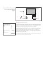
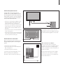
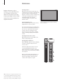
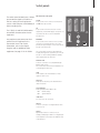
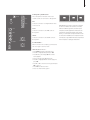
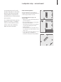
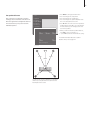
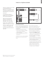
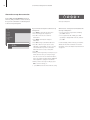
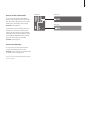
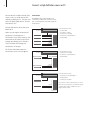
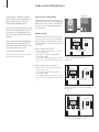
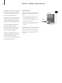
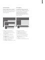
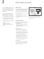
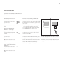
BeoVision 4
Reference book
BeoVision 4 includes the products shown above.
The individual components are referred to by their
respective names in the Guide and Reference
book. The complete setup is referred to as
BeoVision 4.
BeoVision 4
plasma screen
IR receiver
Beo4
remote control
BeoSystem 2
An explanation of symbols
in the Guide and Reference
book
Buttons on the Beo4 remote
control
Cabinet
The Guide and the Reference book
TV
LIST
m
p
Display on the Beo4 remote
control
STORE
Display on the screen
T V 12
This Reference book contains information about connecting and operating external
equipment, as well as an overview of on-screen menus. The Guide contains all the
information you need to know about your Bang & Olufsen products.
We expect your Bang & Olufsen retailer to deliver, install and set up your products.
However, the information required to install and set them up is included in the
Guide and the Reference book. This might be useful if you move your products or
expand your system at a later date.
The Guide and the Reference book both contain an index which can help you find
the specific subject you want to know more about.
Contents
Placement, connections and maintenance, 4
Find out how to handle and place your BeoVision 4, connect additional video
equipment, and where the sockets are placed.
Loudspeaker setup – surround sound, 13
Find out how to turn BeoVision 4 into a surround sound system.
Connect extra equipment, 18
Find out how to connect a set-top box, decoder, High Definition (HD) source or a
PC to BeoSystem 2 and how to register extra equipment.
Audio system with BeoVision 4, 26
Find out how to connect an audio system to BeoSystem 2 and operate an
integrated audio/video system.
Distribute sound and picture with BeoLink, 28
Find out how to make link connections, operate a link system and set up
BeoVision 4 in a link room.
Customise Beo4, 32
Find out how to add and remove Beo4 functions.
Menus, 34
Overview of the on-screen menus.
Index, 41
3
Set up BeoVision 4 and BeoSystem 2
4
We recommend that you follow the
procedure described below when you
set up BeoVision 4:
– Unpack the system and the screen.
– Consider the appropriate
surroundings. Guidelines are
included on this page.
– Mount the wall bracket as
described in the Guide enclosed
with the wall bracket.
– Connect the screen.
– Mount the IR receiver.
– Connect speakers and additional
equipment, as described on the
following pages.
Do not connect your system to the
mains until you have connected your
screen, loudspeakers and other
equipment!
For further information about the
close-up socket panel on BeoSystem 2,
refer to the chapter ‘Close-up socket
panel on BeoSystem 2’ on page 12.
Before you start…
– Make sure that your products are set up,
placed and connected in accordance with
this Guide.
– Do not place any items on top of
BeoSystem 2 or the screen.
– Your products are developed for indoor
use in dry, domestic environments only,
and for use within a temperature range of
10–40ºC (50–105ºF).
– Do not attempt to open your products.
Leave such operations to qualified service
personnel.
BeoSystem 2:
– Place BeoSystem 2 in the Cabinet. If you do
not wish to use the Cabinet, make sure that
there is sufficient space around BeoSystem 2
for ventilation.
– Always place BeoSystem 2 on a firm and
stable surface.
The plasma screen:
– Due to the weight of the screen, any
moving or lifting of the screen should be
done by two persons.
– When lifting the screen, grip the top and
bottom edges.
– Carry the screen in such a way that it is in
an upright position at all times.
– If you must put the screen down at any
time prior to placing it, we recommend
that you rest it in an upright position on its
bottom edge on a stable, flat surface. The
screen is not designed to stand on its own.
It must be supported until mounted on the
wall bracket!
– The picture can be distorted at altitudes
where the air pressure is lower than 833 hPa
(approximately 1500 metres or higher).
– When mounting the screen in the wall
bracket, leave a space of about 10
centimetres at the top, bottom and sides.
Place BeoSystem 2 in the Cabinet. When
connections are complete, attach the back cover
with the four screws included with the Cabinet.
5
Overview of sockets
1
BeoSystem 2:
1 Mains switch
2 IR receiver sockets
3 Close-up socket panel
4 Mains connection
5 Plasma screen socket area
6 Speaker and digital input socket panel
7 AV and aerial socket panel
8 Fan socket
2
The plasma screen:
1 Speaker connection panels*
2 A/V connection panel
3 Mains connection
*When connecting external loudspeakers, connect
them to the loudspeaker sockets on BeoSystem 2
and not to the plasma screen!
5
6
1
3
7
4
2
8
For further information about the sockets, refer to
the chapter ‘Socket panels’ on page 9.
3
6
>> Set up BeoVision 4 and BeoSystem 2
Mount and connect the IR receiver
To facilitate remote control operation of
BeoVision 4 and all connected equipment, you
must connect the IR receiver to BeoSystem 2.
B
C
D
The IR receiver is a kind of ‘eye’ which is
capable of receiving signals from your Beo4
remote control and sending them to
BeoSystem 2. BeoSystem 2 then sends the
appropriate control signals to your plasma
screen or other connected equipment.
White
Blue
Green
Yellow
Black
Brown
Grey
Red
When mounting the IR receiver, make sure to
place the receiver on the same wall as the
screen. If the IR receiver is placed incorrectly,
the light emitted by the screen can impede
remote control operation of BeoVision 4!
When you have mounted the IR receiver as
shown on this page, connect it to the
IR IN socket on BeoSystem 2.
A
B
B
B
D
D
C
C
7
Connect the plasma screen
– Connect one 15-pin plug to the RGB socket on
BeoSystem 2 and the 9-pin plug at the same
end to the RS232 socket on BeoSystem 2.
– Connect the 15-pin plug at the opposite end to
the PC IN socket on the screen, and the 9-pin
plug at the same end to the SERIAL socket on
the screen.
– Connect the IR receiver to the appropriate IR-IN
socket on BeoSystem 2.
– Connect the two mains cords to the appropriate
sockets on BeoSystem 2 and the screen, but do
not connect them to the mains yet!
PC IN
SERIAL
If longer cables are necessary, they are
available from your Bang & Olufsen retailer.
The two plugs at each end of the cable only
match specific sockets, so it is not possible to
connect the cables incorrectly if you follow
the procedure described below:
IR-IN*
RGB
RS232
It is necessary to secure the mains cord in the
cable bands, as shown in the diagram. Otherwise,
the mains cord can be tugged free of the socket.
Aerial and mains connection
Make sure that BeoSystem 2 and the screen
are placed properly before connecting the
system.
> Connect the screen to the mains.
> Connect the aerial to the socket marked VHF/
UHF on BeoSystem 2.
> Connect BeoSystem 2 to the mains.
If you have not yet connected speakers, or you
wish to connect any other equipment to
BeoSystem 2, do not connect to the mains yet!
BeoSystem 2
When connections are complete…
Switch on the mains switch on the back of
BeoSystem 2. The system is in standby mode and
ready to be used. You can now begin tuning in
channels, as explained in ‘Tune in TV channels’ on
page 26 in the Guide.
BeoVision 4 was designed to be left in standby
mode when not in use. Therefore, to facilitate
remote control operation, it is essential that you
leave the mains switch on.
Maintenance
8
Regular maintenance, such as
cleaning, is the responsibility of the
user. To achieve the best result,
follow the instructions to the right.
Contact your Bang & Olufsen retailer
to determine recommendations for
regular maintenance.
Cleaning surfaces…
Wipe dust off the surfaces using a dry, soft
cloth. Remove grease stains or persistent dirt
with a soft, lint-free, firmly wrung cloth,
dipped in a solution of water containing only
a few drops of mild detergent, such as
washing-up liquid. These cleaning
instructions apply to any stand or wall
bracket as well.
About the plasma screen…
Clean only with a dry, soft cloth. Do not use
liquid cleaners or aerosol cleaners.
Never use alcohol or other solvents to clean any
part of BeoVision 4!
Do not allow still pictures to be displayed on
the screen for an extended period of time, as
this can cause a permanent after-image to
remain on the screen. Examples of still
pictures are logos, video games, computer
images, and images displayed in 4:3 picture
format.
Cleaning the Beo4 remote control
Wipe the Beo4 remote control with a soft,
lint-free, firmly wrung cloth.
2
Changing the Beo4 batteries…
When ‘BATTERY’ appears in the Beo4 display,
it is time to change the batteries in the
remote control.
The Beo4 requires three batteries. Use 1.5
volt (size AAA) Alkaline batteries only.
Replace the batteries as shown on this page.
Keep a finger on top of the batteries until the
lid is replaced.
When you have replaced the batteries, you
must wait for about 10 seconds until ‘TV’
appears in the display. The Beo4 remote
control is then ready for use again.
1
3
2
1
NOTE! If the front screen glass should crack or chip,
or if it should be damaged in any way, it must be
replaced immediately, as it could otherwise cause
injury. Please contact your Bang & Olufsen retailer.
Socket panels
The socket panel on BeoSystem 2 allows
you to connect signal input cables as
well as a variety of extra equipment,
such as a DVD player or a linked Bang &
Olufsen audio system.
The V.TAPE, AV and DECODER sockets
are available for connection of extra
equipment.
Any equipment you connect to these
sockets must be registered in the
Connections menu. For further
information, refer to the chapter
‘Register and use additional video
equipment’ on page 32 in the Guide.
9
AV and aerial socket panel
3
SPDIF
V.TAPE
21-pin socket for the connection of a BeoCord
V 8000 video tape recorder.
VGA-IN
AV
21-pin socket for the AV connection of other
equipment, such as a DVD player, set-top box or a
second decoder. Do not connect baseband
decoders here.
DECODER
21-pin socket for the connection of a secondary
set-top box or a primary decoder. The socket
provides the opportunity to connect either an AV
decoder or an RF decoder.
The socket may be used for an AV 2 Expander
instead, which gives the opportunity to connect a
decoder or other non-Bang & Olufsen auxiliary
video equipment at the same time.
MASTER LINK
Socket for connection of a compatible Bang &
Olufsen audio system.
The socket is also used for BeoLink distribution of
sound throughout the house.
LINK
Aerial output socket for distribution of video
signals to other rooms.
VHF/UHF
Aerial input socket from your external aerial or
cable TV network.
ATTN. ON/OFF
Aerial signal attenuator. Options are:
OFF:
Normal setting
ON:
Signals damped
IR OUTPUT
For connection of a set-top box.
VGA-IN
Socket for connection of a High Definition video
source or a PC.
SPDIF 3
Digital input socket for connection of, for
example, a DVD player. SPDIF 3 is for digital input
from equipment connected to the VGA-IN socket
on BeoSystem 2.
V.TAPE
DECODER
AV
IR-OUT
LINK
ATTN.
MASTER LINK
OFF
VHF/UHF
75 Ω
AV and aerial socket panel.
ON
10
>> Socket panels
Speaker and digital input socket panel
FRONT
CENTRE
FRONT
1
FRONT
The two sockets are used for connecting the front
speakers in a surround sound setup.
CENTRE
Socket for connecting centre speakers in a
surround sound setup.
REAR
The two sockets are used for connecting the rear
speakers in a surround sound setup.
SUBWOOFER
Socket used for connecting a BeoLab 2 subwoofer
in a surround sound setup.
SPDIF 1
Digital input socket for connection of, for
example, a DVD player. SPDIF 1 is for digital input
from equipment connected to the AV socket on
BeoSystem 2.
SPDIF 2
Digital input socket for connection of, for
example, a DVD player. SPDIF 2 is for digital input
from equipment connected to the V.TAPE socket
on BeoSystem 2.
If the V.TAPE socket is set up for V.Mem or None,
the SPDIF 2 socket is dedicated to the equipment
connected to the DECODER socket instead.
Additional sockets
SPDIF
2
REAR
SUBWOOFER
REAR
ON/OFF
Mains switch.
IR IN
For connection of a BeoLink IR receiver enabling
remote control operation of BeoVision 4.
MAINS
Connection to the mains.
RGB
For connection of the screen.
RS232
For connection of the screen.
FAN
For connection of an external ventilator.
S-VHS / VIDEO / R / L / PHONES
The Camcorder and headphones sockets. For
more information, refer to the chapter ‘Close-up
socket panel on BeoSystem 2’ on page 12.
11
ON/OFF
RGB
Socket panel – plasma screen
The socket panel on the back of the screen
contains sockets for connection to BeoSystem 2.
IR-IN
RS232
DVI
Socket for connection of a High Definition video
source or a PC.
PC IN
Socket for connection to the RGB socket on
BeoSystem 2.
S-VHS
VIDEO
SERIAL
Socket for connection to the RS232 socket on
BeoSystem 2.
R
L
0/12 V CONTROL
PHONES
FAN
MAINS
For the installer…
When connections are complete, you must select
the screen type in a Service menu.
While BeoVision 4 is on…
> Press MENU to bring up the main menu.
> Press p to highlight Setup and press GO.
> Press 0 twice, followed by GO. The Service
menu appears.
> Press 1 to bring up the Monitor menu.
> Press p to highlight Plasma version setup, and
press GO.
> Press m or p to select the screen type and press
GO to store it.
> Press EXIT to leave the menu.
> Press • to switch off the system.
DVI
PC IN
SERIAL
IMPORTANT! If you wish to connect a computer
to the screen and use the screen as a monitor,
make sure that BeoSystem 2, BeoVision 4, the
computer, and all equipment connected to the
computer are all disconnected from the mains
before you connect the computer and the screen
to each other. In addition, the computer must be
connected to a grounded wall outlet as specified
in the computer’s setting-up instructions.
Close-up socket panel on BeoSystem 2
12
You can connect headphones and
listen to a TV programme, or you can
connect a Camcorder and watch your
home movies on BeoVision 4. If you
have connected, for example, a
BeoCord V 8000 video tape recorder,
you can copy Camcorder recordings
onto a videotape.
The close-up socket panel
S-VHS
For the connection of S-VHS or Hi-8 Camcorders
only.
VIDEO – R – L
These sockets are for connection of a video
camera:
L – R:
For audio connection (right and left
sound channel respectively).
VIDEO: For the Video signal.
PHONES
You can connect stereo headphones to the socket
marked PHONES. The speakers connected to
BeoSystem 2 can then be cut out by pressing the
middle of the Beo4 volume button.
Watch Camcorder on BeoVision 4
To watch your Camcorder recordings, connect
the Camcorder and switch BeoVision 4 on.
When you start playback on your Camcorder,
BeoSystem 2 automatically registers the
signal and you can see the pictures from the
Camcorder on BeoVision 4.
If the signal from the Camcorder is switched
off…
> Press LIST repeatedly to display CAMERA on
Beo4 and press GO.
In order to display CAMERA on Beo4, you must
first add it to the Beo4 list of functions. For further
information, refer to the chapter ‘Customise Beo4’
on page 32.
S-VHS
VIDEO
R
L
PHONES
Copy from a Camcorder
If you have connected a video tape recorder,
such as a BeoCord V 8000, to BeoSystem 2,
and you connect your Camcorder to the
Camcorder and headphones sockets, you can
copy Camcorder recordings onto a videotape.
While the tape is being copied, you can watch
a TV programme or switch BeoSystem 2 to
standby.
To copy a recording from a Camcorder…
> Connect your Camcorder and start playback on
the Camcorder.
> Press RECORD to prepare BeoCord V 8000 for
recording.
> Press RECORD again to start recording.
> Press V MEM and then STOP to pause a
recording.
> Press RECORD to resume a paused recording,
or…
> …press STOP again to stop a recording entirely.
Loudspeaker setup – surround sound
A surround sound setup fits easily
into your living room. Let the picture
determine your ideal listening and
viewing position. You get the best
sound experience in the area created
by the speakers.
In a surround sound setup, you must
calibrate the speakers. To calibrate
means to set the balance between
speakers. Refer to the following
pages for further instruction.
Place external speakers
The three illustrations to the right show
examples of BeoVision 4 and speakers placed
in various types and sizes of rooms.
The following guidelines apply for all
speaker setups:
– Always use your most powerful speakers as
your front speakers.
– Place your speakers where you want them
before you connect them.
– The best placement for the rear speakers is
on either side behind your favourite
listening position.
– The front and rear sets of speakers do not
necessarily have to be placed in the corners
of the room.
– If you connect a BeoLab 2 subwoofer, refer
to the subwoofer’s own Guide for
information about placement possibilities.
13
14
>> Loudspeaker setup – surround sound
Connect speakers
L
R
You can connect Bang & Olufsen speakers
and a BeoLab 2 subwoofer to BeoVision 4 via
the connection panel on the rear of
BeoSystem 2. The speakers must be Bang &
Olufsen Power Link speakers.
BeoSystem 2
SUBWOOFER
You can loop the signals through from
speaker to speaker (as described in the Guide
enclosed with your speakers), or you can
connect each individual speaker to a socket.
If necessary, longer cables and adaptors are
available from your Bang & Olufsen retailer.
Use the cables enclosed with the speakers to
make the following connections:
> Connect the two front speakers to the sockets
marked FRONT.
> Connect the two rear speakers to the sockets
marked REAR.
> Connect the centre speakers to the socket
marked CENTRE. Loop the signals through from
speaker to speaker when connecting the centre
speakers.
> Connect the subwoofer to the socket marked
SUBWOOFER.
Always remember to set the L – R – LINE switch on
both the front and rear sets of speakers to L or R
(left and right channel) to indicate their position in
each speaker set. Set the left front speaker to L,
the right rear speaker to R, and so on.
If you have only one set of speakers, connect
these to the sockets marked FRONT.
FRONT
L
R
>
>
>
>
Sound
1
2
3
4
5
6
Adjustment
Speaker type
Speaker distance
Speaker level
Speaker mode
Sound system
Front
Beolab 1
>
Rear
Beolab 6000
Subwoofer
>
Yes
>
>
REAR
CENTRE
Press MENU to bring up the main menu.
Press 3 to bring up the Setup menu.
Press 2 to bring up the Sound menu.
Press 2 again to bring up the Speaker type
menu.
Press p or m to reveal your speaker type
and n to move on to the next speaker set.
Choose None if no speakers are connected.
If you have a BeoLab 2 subwoofer, press n to
move the cursor to Subwoofer and press p to
change to Yes.
Press GO to store your choices, or…
…press EXIT to leave the menu without storing.
If you have only one set of speakers, set ‘Front’ to
‘None’ – NOT to your speaker type!
For further information about the ‘Speaker type’
menu, refer to page 38.
15
Set speaker distance
Place yourself in your favourite television
viewing position and switch on BeoVision 4.
Enter the approximate straight-line distances
in metres between your position and the
individual speakers.
1
2
3
4
5
6
Adjustment
Speaker type
Speaker distance
Speaker level
Speaker mode
Sound system
Front
4 metres
TV
3 metres
Rear
Front
4 metres
Rear
2 metres
2 metres
Distance to viewing position
FRONT
FRONT
CENTRE
REAR
Press MENU to bring up the main menu.
Press 3 to bring up the Setup menu.
Press 2 to bring up the Sound menu.
Press 3 to bring up the Speaker distance menu.
The connected speakers are shown.
> Press l or n to move the cursor from speaker to
speaker and press m or p to select the distance
in metres between your viewing position and
each of the speakers.
> When you have entered the speaker distances,
press GO to store your settings, or…
> …press EXIT to leave the menu without storing.
>
>
>
>
Sound
REAR
You do not have to enter a distance for a BeoLab 2
subwoofer, as the placement of a subwoofer has
little impact on the sound.
For further information about the ‘Speaker
distance’ menu, refer to page 38.
16
>> Loudspeaker setup – surround sound
Calibrate the sound level
When you have connected the necessary
speakers in a surround sound setup to
BeoSystem 2, you have to perform a speaker
calibration.
A calibration sound is produced alternately in
each of the speakers you have connected in
your surround sound setup. Your task is to
adjust the sound level from all the connected
speakers to match the sound level from the
centre speakers. You can choose whether you
want the sound sequence to occur automatically or manually.
Once you have performed your speaker
calibration, you only need to re-calibrate the
speaker sound if you make changes to the
setup, for example, if you move one or more
of the speakers.
It is not necessary to calibrate subwoofer sound in
a surround sound setup. If you still wish to adjust
subwoofer sound when your speaker calibration is
complete, refer to the chapter ‘Adjust picture and
sound settings’ on page 35 in the Guide.
The sound level from the centre speakers
functions as your point of comparison with the
external speakers and can not be adjusted.
1
2
3
4
5
6
Adjustment
Speaker type
Speaker distance
Speaker level
Speaker mode
Sound system
Front
0
Press MENU to bring up the main menu.
Press 3 to bring up the Setup menu.
Press 2 to bring up the Sound menu.
Press 4 to bring up the Speaker level menu. TV
is highlighted and sound is cut in on the centre
speakers.
> Press m or p to adjust the speaker sound and l
or n to move to another speaker.
> When you have adjusted the sound for all the
speakers in your surround sound setup, press
GO to store your settings, or…
> …press EXIT to leave the menu without storing.
>
>
>
>
Sound
TV
(0)
Rear
0
Press MENU for automatic sequence
Front
0
Rear
0
For further information about the ‘Speaker level’
menu, refer to page 38.
17
Set a default speaker mode
You can preset two default speaker modes;
one to be used each time you switch on a
video source in your system, and one to be
used each time you switch on an audio source
connected to your system. You can still select
a different speaker mode, as described on
page 10 in the Guide.
1
2
3
4
5
6
Adjustment
Speaker type
Speaker distance
Speaker level
Speaker mode
Sound system
Video
Speaker 3
Press MENU to bring up the main menu.
Press 3 to bring up the Setup menu.
Press 2 to bring up the Sound menu.
Press 5 to bring up the Speaker mode menu.
Press or to switch between speaker modes
and or to move between Video and Audio.
> When you have selected your default speaker
modes, press GO to store your settings, or…
> …press EXIT to leave the menu without storing.
>
>
>
>
>
Sound
Audio
Speaker 2
For further information about the ‘Speaker mode’
menu, refer to page 39.
Connect additional equipment
18
You can connect different types of
audio and video equipment to
BeoSystem 2, such as a video
recorder, set-top box or Camcorder.
When connecting video equipment
to BeoSystem 2, remember to use the
AV socket on BeoSystem 2 first, if it is
vacant.
Refer to the guides included with
your additional equipment to make
sure it is connected properly.
Remember to register all connected
equipment. For further information
refer to the chapter ‘Register and use
additional video equipment’ on page
32 in the Guide.
AV 2 Expander
Game console, Camcorder, etc.
The optional AV 2 Expander accessory is a
SCART expander for connection of nonBang & Olufsen equipment, such as decoders,
game consoles, and cameras to the DECODER
socket on BeoSystem 2. Use a 21-pin cable to
connect one plug to the socket marked TV on
the Expander box, and connect the other
plug to the socket marked DECODER on
BeoSystem 2. Remote control operation of
equipment connected via the AV 2 Expander
is not possible.
We recommend that you use the close-up
socket panel for equipment you connect on a
temporary basis, such as a game console or
Camcorder. The use of these sockets is
explained in the chapter ‘Close-up socket
panel on BeoSystem 2’ on page 12.
Video recorder
Use a 21-pin cable to connect a Bang &
Olufsen video recorder to the V.TAPE socket
on BeoSystem 2. Connect the cable from the
aerial to the input socket on the video
recorder. Forward the aerial cable to the
aerial socket on BeoSystem 2.
DVD player
Use a 21-pin cable to connect a DVD player,
such as a Bang & Olufsen DVD 1, to
BeoSystem 2. Connect one end to the socket
marked AV on your DVD player and the other
to the socket marked AV on BeoSystem 2.
Connect the socket marked DIGITAL OUTPUT
on DVD 1 to the SPDIF 1 socket on
BeoSystem 2. If the required cable is not
enclosed, it is available from your Bang &
Olufsen retailer.
Connect a set-top box or decoder
Connect a set-top box* to the V.TAPE,
AV or DECODER sockets on
BeoSystem 2. If the sockets are all in
use, you can also connect a set-top
box to BeoSystem 2 via the close-up
socket panel.
Set-top box (DTV or V.AUX)
If you have a High Definition (HD)
set-top box, refer to page 22 for
information about connection and
registration.
Primary set-top box
STB(DTV)
IR transmitter
connection
IR transmitter
connection
BeoSystem 2
Set-top box connection
Disconnect all involved systems from the mains
before you connect external equipment. Use
the 21-pin AV cable to connect the set-top box
to BeoSystem 2:
> Connect one socket to the set-top box.
> Run the cable to the V.TAPE, AV or DECODER
socket on the back of BeoSystem 2.
> Connect the IR transmitter to the IR OUTPUT
socket on BeoSystem 2.
> Fasten the IR transmitter to the IR receiver of
the set-top box.
To be able to use the remote control included with
your set-top box, do not cover its IR receiver
entirely.
*NOTE! Set-top boxes must be set up in accordance
with the documentation enclosed with them.
Secondary set-top box
STB(V.AUX)
AV
connection
It is also possible to connect a
decoder to either the DECODER or
the AV socket on BeoSystem 2.
Make sure that all connected
equipment is registered in the
Connections menu. For further
information, refer to the chapter
‘Register and use additional video
equipment’ on page 32 in the Guide.
19
If you connect two set-top boxes…
You will need an IR Y-adaptor (index number
6174171) to connect two set-top boxes to
BeoSystem 2. Please contact your Bang & Olufsen
retailer. Follow the procedure described below to
connect two set-top boxes to BeoSystem 2:
> Connect your primary and secondary set-top
boxes to the AV and DECODER sockets on
BeoSystem 2 (or the DECODER and V.TAPE
sockets if you have connected equipment to the
AV socket) via 21-pin AV cables as shown.
> Connect the IR Y-adaptor to the IR OUTPUT
socket on BeoSystem 2.
> Connect the IR transmitter for your primary settop box to the chrome-coloured socket on the
IR Y-adaptor, and fasten the other end to the IR
receiver on your primary set-top box.
> Connect the IR transmitter for your secondary
set-top box to the gold-coloured socket on the
IR Y-adaptor, and fasten the other end to the IR
receiver on your secondary set-top box.
> Register your primary set-top box in the
Connections menu as STB (DTV) and your
secondary set-top box as STB (V.AUX).
20
>> Connect a set-top box or decoder
Alternative set-top box connection
If the V.TAPE, AV and DECODER sockets are
all in use, and you want to connect a set-top
box, you can connect the second set-top box
to the close-up socket panel.
Setup
1
2
3
4
5
6
Tuning
Sound
Picture
Connections
Menu
Clock
Camcorder
STB (DTV)
S-VHS
VIDEO
R
L
PHONES
Close-up socket panel.
If you connect a set-top box to the close-up
socket panel…
> Press MENU to bring up the main menu.
> Press 3 to bring up the Setup menu.
> Press p to move the cursor down to
Connections.
> Press MENU. Connections changes to
Camcorder.
> Press GO to bring up the Camcorder menu.
> Press m or p to view your options. Select
STB (DTV) or STB (V.AUX). You can, of course,
select Camcorder if you have connected a
Camcorder to the close-up socket panel.
> Press GO.
> When you have registered your set-top box, you
will be asked to select your set-top box type
from an on-screen list. For further information,
refer to the chapter ‘Register and use additional
video equipment’ on page 32 in the Guide.
> When you have selected your STB type, press
GO to store the settings, or…
> …press EXIT to leave the menu without storing
Gain access to a set-top box connected to the
close-up socket panel…
> If your set-top box is registered as STB (DTV),
press DTV on Beo4.
> If it is registered as STB (V.AUX), press LIST
repeatedly to display V.AUX on Beo4, and then
press GO.
In order to display V.AUX on Beo4, you must first
add it to the Beo4 list of functions. For further
information, refer to the chapter ‘Customise Beo4’
on page 32.
21
Connect an AV or RF decoder
To connect an AV decoder (a baseband
decoder, such as Canal+), connect the cable
from the aerial to BeoSystem 2. Connect the
AV decoder to the 21-pin socket marked
DECODER on BeoSystem 2.
If you wish to connect an RF decoder, then
remember to connect the external aerial
cable to the decoder input socket and then
forward the cable to the BeoSystem 2 aerial
socket (marked VHF/UHF). Connect the RF
decoder to the 21-pin socket marked
DECODER on BeoSystem 2.
Connect two decoders
To connect two decoders to BeoSystem 2,
connect your primary decoder to the
DECODER socket and your secondary decoder
to the AV socket on BeoSystem 2.
Do not connect an unclamped baseband decoder
to the AV socket!
BeoSystem 2
Decoder 1
Decoder 2
Connect a High Definition source or PC
22
You can connect a High Definition (HD)
source, such as a set-top box or DVD
recorder, to BeoSystem 2. This gives you
access to digital video sources. You can
also connect a PC.
You can also connect these sources to
BeoVision 4.
Make sure you register all connected
equipment in the BeoSystem 2
Connections menu. Note, however, that
connection of HD sources may limit or
change some BeoSystem 2 functions.
These limitations and changes are
described in this chapter.
Connection
The VGA-IN socket on BeoSystem 2 is for
connection of a HD source, such as a set-top
box, or a PC. Examples of possible setups are
shown below.
BeoVision 4
In the Connections menu:
– Set AV to DVD
– Set V Mem to V Mem
– Set Decoder to PC (VGA)
– Set Camera to STB (DTV/DVI) or
STB (AUX/DVI).
DVI
SPDIF1
HD STB
L R VIDEO
AV
DVD
V TAPE
V MEM
PC
VGA-IN
DECODER
BeoSystem 2
For further information about the
Connections menu, refer to page 40.
BeoVision 4
In the Connections menu:
– Set Decoder to PC (VGA)
– Set Camera to STB (DTV/DVI) or
STB (AUX/DVI).
DVI
SPDIF1
HD STB
L R VIDEO
PC
VGA-IN
DECODER
BeoSystem 2
BeoVision 4
In the Connections menu:
– Set Decoder to STB (DTV/Ypbr) or
STB (AUX/Ypbr)
– Set Camera to PC (DVI).
DVI
PC
HD STB
If you wish to connect a HD set-top box or other
HD source to BeoSystem 2, note that this requires
a special cable, which is available from your
Bang & Olufsen retailer.
SPDIF3
VGA-IN
BeoSystem 2
23
Registration
Get access to HD sources or a PC
HD equipment can be registered with the AV,
Decoder and Camera sockets. Camera is
accessed by highlighting Decoder and
pressing the MENU button on Beo4.
HD sources are accessible via the Beo4 remote
control.
Setup
1
2
3
4
5
6
Tuning
Sound
Picture
Connections
Menu
Clock
V. Mem
V. Mem
AV
DVD
Decoder
Decoder
HD options in the Connections menu:
AV
DVD (YPbr)… for a DVD player connected to the
VGA-IN socket on BeoSystem 2.
DVD2 (YPbr)… for a second DVD player or video
recorder connected to the VGA-IN socket on
BeoSystem 2.
Decoder
STB (DTV/YPbr), STB (AUX/YPbr)… for a set-top
box connected to the VGA-IN socket on
BeoSystem 2.
PC (VGA)… for a PC connected to the VGA-IN
socket on BeoSystem 2.
Camera
STB (DTV/DVI), STB (AUX/DVI)… for a set-top
box connected to the DVI socket on BeoVision 4.
PC (DVI)… for a PC connected to the DVI socket
on BeoVision 4.
Press to switch on a set-top box
registered as STB (DTV/DVI) or
STB (DTV/Ypbr)
DTV
Press repeatedly to display
V.AUX on Beo4
LIST
Press to switch on a source
registered as V.AUX or AUX,
such as a set-top box registered
as STB (AUX/DVI)
GO
Press LIST repeatedly to display
PC on Beo4
LIST
Press GO to switch on a
connected PC
GO
In order to display V.AUX or PC
on Beo4, you must add them to
the Beo4 list of functions. Refer
to the chapter ‘Customise Beo4’
on page 32 for further
information.
If you select PC as your source,
you can not call up the main
menu on the screen without
choosing another source first,
such as TV. Note also that
adjustment of brightness, colour,
contrast or tint must be done via
the PICTURE menu, and not via
the PC. Refer to ‘Store picture
adjustments’ on page 35 in the
Guide for further information.
V.AUX
PC
Do not allow still pictures, such as computer
images, to be displayed on the screen for an
extended period of time, as this can cause a
permanent after-image to remain on the
screen!
NOTE! If you have connected HD equipment to
BeoSystem 2, some video functions are affected:
– There is no on-screen status display, but the
menu system is still accessible;
– The Set-top Box Controller menu described on
page 20 in the Guide does not appear;
– If you have selected FORMAT 2 for letter-box
pictures as described on page 11 in the Guide,
you cannot scroll the picture up or down;
– You cannot distribute sound or picture from a
HD source to a product in a link room.
– You cannot record a HD source, unless your
HD equipment also provides a Standard
Definition (SD) signal;
– You cannot select the HD source when using
the P-AND-P function described on page 14 in
the Guide.
24
>> Connect a HD source or PC
Adjust the HD picture
You may find it necessary to adjust the
picture when using a HD source with
BeoSystem 2. Use your Beo4 remote control
to adjust the picture placement, size and
proportions.
While your HD source is on…
Press LIST repeatedly until
FORMAT is shown
LIST
FORMAT
Press to be able to adjust the
picture
9
Press to move the picture up or
down
m
p
Press to move the picture left or
right
l n
Press to decrease picture height
Press to increase picture height
Press to decrease picture width
Press to increase picture width
Press to store your settings
GO
Press EXIT to return without
storing your settings
EXIT
25
Audio system with BeoVision 4
26
If you connect a compatible Bang &
Olufsen audio system to BeoSystem 2,
you will obtain the benefits of an
integrated audio/video system.
Play a CD on your audio system using
speakers connected to BeoSystem 2,
or switch on a TV programme and
send the sound to your audio system
speakers.
Your systems can be placed together
in one room, or in two rooms with
BeoVision 4 placed in one room, and
the audio system with a set of
speakers placed in another.
Not all Bang & Olufsen audio systems support
integration with the BeoSystem 2.
Connect your audio system
BeoSystem 2
Using a Master Link cable, connect the one
multi-pin plug to the socket marked MASTER
LINK on BeoSystem 2, and the other multi-pin
plug to the socket marked MASTER LINK on
the audio system.
MASTER
LINK
Option setting
If BeoVision 4 has been set up in an AV system,
you may need to set it to the correct Option.
Option setting is done with the Beo4 remote
control and with the entire system switched
to standby.
Option setting for BeoVision 4…
> While holding down the • button, press LIST.
> Let go of both buttons.
> Press LIST repeatedly to display OPTION? on
Beo4, and press GO.
> Press LIST repeatedly to display V.OPT on Beo4,
and then key in the appropriate number (0, 1 or
2).
Option setting for the audio system…
> While holding down the • button, press LIST.
> Let go of both buttons.
> Press LIST repeatedly to display OPTION? on
Beo4, and press GO.
> Press LIST repeatedly to display A.OPT on Beo4,
and then key in the appropriate number (0, 1, or
2).
Option 2
Option 0
You can set up BeoVision 4 and an audio system in
one room – all speakers connected to
BeoSystem 2.
Option 1
Option 1
You can choose to set up BeoVision 4 and the
audio system (with a connected set of speakers) in
the same room.
Option 2
Option 2
You can choose to set up your audio system in
one room, and BeoVision 4 in another.
27
To listen to sound from a television source on your
audio system speakers without switching on the
screen, press LIST repeatedly to display AV* on
Beo4, and then press a source button, such as TV.
Use an integrated audio/video
system
When you integrate your audio system and
BeoVision 4, you can choose speakers
appropriate to the current video or audio
programme, and also record video sound on
the audio system.
Video sound recording
If you listen to sound from BeoVision 4 on your
Bang & Olufsen audio system’s speakers, and your
audio system has a recorder, you can record
television sound on the audio recorder. Refer to
the Guide enclosed with your audio system for
further information.
LIST
AV
TV
To listen to sound from a television source on your
audio system speakers with the screen switched
on, press TV, press LIST repeatedly to display AV*
on Beo4, and then press TV again.
TV
LIST
AV
TV
To listen to audio sound on speakers connected to
BeoSystem 2, press LIST repeatedly to display AV*
on Beo4, and then press an audio source button,
such as CD.
LIST
AV
CD
*In order to display AV on Beo4, you must first add
it to the Beo4 list of functions. For further
information, refer to the chapter ‘Customise Beo4’
on page 32.
BeoLink – distribute sound and picture
28
The BeoLink system makes it possible
to distribute picture and/or sound to
other rooms throughout the house.
For example, you can connect
BeoSystem 2 to another video system
or set of speakers in another room,
thereby making it possible to ‘move’
the picture or sound to other rooms.
If you have a BeoLink distribution
system installed, you can use
BeoVision 4 in the main room, such
as a living room, or in a link room,
such as a study or bedroom.
The system modulator ensures that
video sources can be distributed to
the link room. Under certain
circumstances, it may be necessary to
enter modulator settings.
Link connections
The main room system must be connected to
the link room system with a Master Link
cable:
> Connect the Master Link cable to the socket
marked MASTER LINK on BeoSystem 2.
> If you want to distribute video signals as well,
connect an ordinary aerial cable to the socket
marked LINK on BeoSystem 2.
> Run both cables to the link room and follow the
instructions enclosed with the link room
equipment.
If the MASTER LINK socket on BeoSystem 2 already
has an audio system connected, the Master Link
cable must be split in two and joined with the
cable from the link room using a special junction
box. Consult your Bang & Olufsen retailer for
assistance.
BeoSystem 2
LINK
MASTER
LINK
29
System modulator
Link frequency
If you have an audio system or a link speaker
in a link room and you choose to set up a
non-linkable television in the same room, you
must set the system modulator to On. The
factory setting is Off.
If, for example, a TV channel in your area is
broadcasted on the same frequency as the
BeoLink system uses, 599 MHz, you must tune
the system modulator to an unoccupied
frequency. When you change the link
frequency in the main room system, make
sure that the link frequency in the link room
system corresponds.
Tuning
Tuning
1 TV
3 Link frequency
1 TV
3 Link frequency
Tuning
1 TV
3 Modulator
Frequency
Modulator
On
To switch on the system modulator…
> Press MENU to bring up the main menu.
> Press 3 to bring up the Setup menu. Tuning is
already highlighted.
> Press GO to bring up the Tuning menu.
> Press p to move the cursor down to the
Link frequency menu.
> Press MENU to reveal the item Modulator.
> Press GO to bring up the Modulator menu.
> Press m or p to change from Off to On.
> Press GO to store the setting, or…
> …press EXIT to leave all menus without storing.
599
To change the link frequency…
> Press MENU to bring up the main menu.
> Press 3 to bring up the Setup menu.
> Press GO to bring up the Tuning menu.
> Press 2 to bring up the Link frequency menu.
> Press m or p to find an available frequency.
Alternatively, key in the frequency using the
number keys on Beo4.
> Press GO to store your setting, or…
> …press EXIT to leave all menus without storing.
BeoLink – BeoVision 4 in a link room
30
If you have BeoLink installed in your
home and place BeoVision 4 in a link
room, you can operate connected
systems in the main room through
BeoVision 4.
You must follow the procedure
described below when you connect
BeoVision 4 for use in a link room:
1 Connect BeoSystem 2 to the mains.
2 Using the Beo4 remote control,
program BeoSystem 2 to Option
6*.
3 Disconnect BeoSystem 2 from the
mains.
4 Make the connections.
5 Reconnect BeoSystem 2 to the
mains.
Option setting
For your entire system to function properly, it
is essential that the BeoSystem 2 in the link
room is set to the correct Option before you
connect it to the system in the main room!
> While holding down the • button, press LIST.
> Let go of both buttons.
> Press LIST repeatedly to display OPTION? on
Beo4, and press GO.
> Press LIST repeatedly to display V.OPT on Beo4,
and press 6*.
Link room connections
Your BeoSystem 2 in the link room must be
connected to your main room system using
two different cables:
– BeoLink connection (using a Master Link
cable and a junction box).
– Aerial connection (using an ordinary aerial
cable).
BeoLink connection
In the main room: Connect the Master Link
cable to the socket marked MASTER LINK on
the main system. Run the cable to the junction
box, and cut the cable to an appropriate length.
In the link room: Connect the Master Link cable
to the socket marked MASTER LINK on
BeoSystem 2. Run the cable to the junction box,
and cut the cable to an appropriate length.
Inside the junction box: Join the cables as
explained in the Guide enclosed with the box/
cable. This Guide explains all the possibilities for
the box, and how to join the cables.
Aerial connection
Using an ordinary TV aerial cable (coaxial cable),
connect one end to the socket marked LINK on
the main system, and the other end to the aerial
input socket on BeoSystem 2.
Main room
Link room
Option 6
*If you connect BeoVision 4 for use in a link room
where other link systems are already connected,
such as speakers, you must program BeoSystem 2
to ‘Option’ 5 instead.
31
Link room operation
When you are in the link room, you can
operate all connected systems with the Beo4
remote control.
Use sources present only in
one of the rooms…
Press the button for the source
you wish to use
RADIO
A MEM
DTV
Operate the selected source as
usual
Use a source placed in the
main room – source type
present in both rooms…
Press repeatedly to display LINK*
on Beo4
Press the button for the source
you wish to use
LIST
LINK
TV
Operate the selected source as
usual
Use a source placed in the link
room – source type present in
both rooms…
Press the button for the source
you wish to use
Operate the selected source as
usual
TV
Listen to stereo sound in your link room…
Sound distributed from a main room video source,
such as a set-top box, to the link room will usually
be transmitted in mono. However, you can select
stereo sound:
> Press for example DTV to switch on a set-top
box connected to the main room system.
> Press LIST repeatedly to display AV* on Beo4.
> Press DTV again to hear stereo sound.
Main
Mainroom
room
Link
Link room
room
IMPORTANT! While using this function, distribution
of other main room sources to other link room
systems is not possible!
Timed play or timed standby settings can also be
executed on a link room BeoVision 4. They must
be programmed on the system in the main room
and the Timer function must be activated on the
BeoVision 4. For more information, refer to the
chapter ‘Make BeoVision 4 start and stop
automatically’ on page 18 in the Guide.
*In order to display LINK or AV on Beo4, you must
add it to the Beo4 list of functions. For further
information, refer to the chapter ‘Customise Beo4’
on page 32.
Customise Beo4
32
The Beo4 buttons give direct remote
control of a large number of
television functions, and the Beo4
display gives you access to even more
functions.
Set up Beo4
Add an extra ‘button’
If you have a Beo4 remote control already
you can configure the Beo4 to work with
BeoVision 4.
When you add a new function to the Beo4
list, you can then bring up this new ‘button’
in the Beo4 display.
Whenever a source is displayed on
Beo4 (such as TV or RADIO), you can
press the LIST button and bring up
extra functions in the display to help
you operate that source, just as if you
were calling up extra buttons. You
can also switch on extra equipment
connected to BeoSystem 2.
Press and hold the standby
button down
•
Press and hold the standby
button down
•
Press to get access to the Beo4
setup function
LIST
Press to get access to the Beo4
setup function
LIST
Note that Beo4 contains a list of all of
Bang & Olufsen’s extra audio and
video functions, but only those
functions supported by BeoVision 4
work when you call them up in the
Beo4 display.
You can customise your Beo4 list of
functions to suit your needs, and
change the order in which these
extra functions appear when you call
them up.
Let go of both buttons. ADD?
appears in the display
ADD?
Press repeatedly to display
CONFIG? on Beo4
LIST
Press to be able to select the
type of configuration
GO
Press repeatedly to display
VIDEO? on Beo4
LIST
Press to get access to the video
configuration
GO
Press repeatedly to display
VIDEO1 on Beo4*
LIST
Press to store the configuration
GO
STORED appears, indicating that
the configuration has been
stored. You leave the Beo4 setup
function automatically
*If the video configuration does
not contain VIDEO1, select
AVANT instead
CONFIG?
VIDEO?
VIDEO1
STORED
Let go of both buttons. ADD?
appears in the display
ADD?
Press to bring up the list of
available ‘buttons’ to add from.
The first ‘button’ appears in the
display, it flashes on and off
GO
Press to move forwards or
backwards in the list of all extra
‘buttons’
m
p
Press to add and place the
‘button’ on its preset position
or…
GO
…press to insert the ‘button’ at a
specific position in the list
1–9
ADDED appears, indicating that
the ‘button’ has been added.
You leave the Beo4 setup
function automatically
ADDED
33
Move extra ‘buttons’
Remove an extra ‘button’
You can rearrange the order in which the
extra ‘buttons’ appear when you press LIST.
You can remove any of the extra ‘buttons’
that are available when you press LIST.
Press and hold the standby
button down
•
Press and hold the standby
button down
•
Press to get access to the Beo4
setup function
LIST
Press to get access to the Beo4
setup function
LIST
GO
Let go of both buttons. ADD?
appears in the display
ADD?
Press repeatedly to display
MOVE? on Beo4
LIST
Press to bring up the list of extra
‘buttons’. The first ‘button’
appears in the display
Let go of both buttons. ADD?
appears in the display
ADD?
Press repeatedly to display
REMOVE? on Beo4
LIST
GO
Press to bring up the list of extra
‘buttons’. The first ‘button’
appears in the display
GO
Press to move forwards or
backwards in the list of extra
’buttons’
m
p
Press to move forwards or
backwards in the list of extra
’buttons’
m
p
Press to move and place the
displayed ‘button’ as the first in
the list, or…
GO
Press to remove the ‘button’
shown in the display
GO
…press to move the ‘button’ to a
specific position in the list
MOVED appears, indicating that
the ‘button’ has been moved.
You leave the Beo4 setup
function automatically
MOVE?
1–9
REMOVED appears, indicating
that the ‘button’ has been
removed. You leave the Beo4
setup function automatically
3
REMOVE?
Add an extra ‘button’ to Beo4, either to the top of
the list or to a specific position.
REMOVED
GO
3
MOVED
Move extra ‘buttons’, either to the top of the list
or to a specific position.
On-screen menus
34
This chapter illustrates the overall
structure of the menu system, to help
you find your way through the onscreen menus the system offers.
You can also find detailed information
about the individual menus which
offer numerous setting up and
adjustment options.
MENU
Timer play
TV list
Set timer
Setup
Activate timer
Tuning
Sound
TV
Picture
Adjustment
Connections
Speaker type
Add program
Menu
Speaker distance
Auto tuning
Clock
Speaker level
Manual tuning
V. Mem
Speaker mode
Sound system
The extended on-screen menu system. The
presence of the greyed menu items depends on
whether these options are available in your system.
Press MENU on Beo4 to access the main menu.
Link frequency
Edit TV list
35
Source Pr Start
TV
Stop
Date
1 13:30 - 14:30 27 Oct OK
Press MENU for Timer index
What’s on the Set timer menu…
Source
Depending upon what you choose, Source
indicates either that a specific source is to be
switched on and off, or that the system is to be
switched off. Options* are:
TV
To switch on TV.
V.Mem
To switch on a video recorder.
CD
To switch on a CD player.
A.Mem
To switch on an audio recorder.
Radio
To switch on a radio.
N.Music, N.Radio
To play music stored on your PC or radio sites
on the Internet (For a connected PC with a
BeoLink PC box).
Standby
To switch BeoVision 4 off. Note that if you have
other compatible video or audio systems
connected to BeoSystem 2, they will be
switched off as well, even if you have
programmed these systems to play.
Pr (Program number)
Choose the program number you want.
Start and Stop (Start and stop times)
Key in the times when you want the system to
start and/or stop playing. If you have chosen
Standby as your source, then enter only the stop
time.
Date or Days
Fill in the date you want the system to start
playing or switch off.
OK
When OK is highlighted, press GO to store your
timed play or timed standby settings.
*If Radio is available, CD and A.Mem will also
appear, regardless of whether they are actually
present or not.
Index
TV
TV
Standby
Activate timer
1
3
13:30 - 14:30
17:10 - 19:00
23:10
27 Oct
27 Oct
MTWT . . .
Yes
Press MENU to clear timer
What’s on the Timer index…
The Timer index lists all your programmed Timers.
> Press GO when a Timer is highlighted to edit
this Timer.
> Press MENU when a Timer is highlighted to
delete this Timer.
What’s on the Activate Timer menu…
> Select Yes to activate your Timers and select No
to deactivate Timers.
36
>> On-screen menus
1
2
..
12
13
14
BBC 1
BBC 2
EUROSPRT
........
MTV
Freq
Pr
210 12
Freq
Pr
210 12
Press >> to
move
What’s on the Edit TV list menu…
When the TV list appears on the screen you have
several options:
– Move TV channels to change the order in which
they appear on the TV list.
– Delete unwanted TV channels.
– Name or change the name of your TV channels.
For further information, refer to the chapter ‘Edit
tuned TV channels’ on page 28 in the Guide.
What’s on the Add program menu…
Freq (frequency)
Shows the frequency during the Add program
process.
Pr (program number)
Shows the program number during the
Add program process.
What’s on the Auto tuning menu…
Freq (frequency)
Shows the frequency during the Auto tuning
process.
Pr (program number)
Shows the program number during the Auto
tuning process.
37
Freq
Pr
210 1
Name
........
More
What’s on the first TV manual tuning menu...
Freq (frequency)
Searching stops at the first channel producing
an acceptable signal. If you know a channel’s
exact frequency number, key it in directly using
the number keys on the Beo4 remote control.
(System)
If System appears in the menu, make sure that
the correct broadcast system is displayed before
you start tuning.
Pr (program number)
Enter the program number (1-99) you wish to
give the channel.
Name
The name you give a channel will appear in the
TV channel list. A name may contain up to eight
characters, including the letters A-Z, numbers
and full stop. For further information, refer to
the chapter ‘Name tuned channels’ on page 30
in the Guide.
More
If it is necessary to fill in extra information,
move to More and press GO. A second manual
tuning menu appears.
Fine
0
Decoder
Off
Sound
Stereo-2
What’s on the second TV manual tuning
menu…
Fine (fine tuning)
The TV automatically tunes to the best possible
picture. However, neighbouring channels may
blur the picture slightly, in which case fine
tuning may be required. The fine tuning range is
+8 to -8.
Decoder
If you have only one decoder connected, your
options are On or Off. If you have two decoders
connected to BeoSystem 2, you can choose
between Dec1, Dec2, or Off.
Sound (mono/stereo/language)
Several types of sound may be available for a TV
channel. Examples can be stereo sound, mono
sound, or other languages.
Even though you store a type of sound/
language, you can switch between the various
types while you are watching a particular TV
channel. For information about the various
types of sound available, refer to the chapter
‘Change sound type or language’ on page 9 in
the Guide.
Volume
32
Bass
0
Treble
0
Loudness
On
What’s on the Adjustment menu…
Volume
The volume level can be adjusted in steps of
two within a range of 00 to 72.
Bass
Bass tone can be adjusted in steps of one within
a range of +6 to -6. 0 is the neutral setting.
Treble
Treble tone can be adjusted in steps of one
within a range of +6 to -6. 0 is the neutral
setting.
Loudness
Loudness can be set to On or Off. The loudness
function is used to compensate for the human
ear’s lack of sensitivity to high and low
frequencies. It boosts the low and the high
frequencies when you are listening to low
volume levels so that the music becomes more
dynamic.
Subwoofer (only available if you have connected
a BeoLab 2 subwoofer to BeoSystem 2).
Can be adjusted in steps of one within a range
of +9 to -9. 0 is the neutral setting.
38
>> On-screen menus
Front
Beolab 1
Rear
Beolab 6000
Subwoofer
Yes
Front
4 metres
TV
3 metres
Rear
2 metres
Front
Front
4 metres
0
Rear
Rear
2 metres
Distance to viewing position
What’s on the Speaker type menu…
Front
Select the speakers you have connected from
the available options. If no speakers are
connected, select None.
Rear
Select the speakers you have connected from
the available options. If no speakers are
connected, select None.
Subwoofer
Indicate whether you have connected a
BeoLab 2 subwoofer. Options are Yes or No.
What’s on the Speaker distance menu…
Front
Select the approximate straight-line distance in
metres between your viewing position and each
of the speakers.
Rear
Select the approximate straight-line distance in
metres between your viewing position and each
of the speakers.
TV
Select the approximate straight-line distance in
metres between your viewing position and
BeoVision 4.
TV
(0)
0
Front
0
Rear
0
Press MENU for automatic sequence
What’s on the Speaker level menu…
Front
Adjust the sound level from your left and right
front speakers.
Rear
Adjust the sound level from your left and right
rear speakers
– the two sound sequence options
Manual (default option)
If you select the manual sequence, the sound
follows the speaker you highlight on the menu.
You can then adjust the sound accordingly.
Automatic
If you select the automatic sequence, the sound
shifts automatically between the external
speakers every 2–3 seconds. To adjust the
speaker levels, you must move the cursor to the
speaker you want to adjust first.
39
Video
Speaker 3
Audio
Sound
Speaker 2
1
2
3
4
5
6
What’s on the Speaker mode menu…
Video
You can preset a speaker mode for video
sources. Options are:
Speaker 3… The centre speakers, front speakers
and the BeoLab 2 subwoofer are active.
Speaker 5… Surround sound from all speakers
including the BeoLab 2 subwoofer. For
programmes encoded in Surround Sound.
Audio
You can preset a speaker mode for connected
audio sources. Options are:
Speaker 2… Stereo sound in the two front
speakers. The BeoLab 2 subwoofer is active.
Speaker 4… Enhanced stereo sound in the front
and rear speakers. The BeoLab 2 subwoofer is
active.
Time
Date
Year
Synch
14:25 Thu 2 Nov 2000 No
Adjustment
Speaker type
Speaker distance
Speaker level
Speaker mode
Sound system
What’s on the Sound system menu…
Sound systems that can appear in the menu are:
DOLBY 3 STEREO, DOLBY PRO LOGIC, DOLBY
DIGITAL, DOLBY D + PRO LOGIC, DTS DIGITAL
SURROUND, MONO/STEREO.
What’s on the Clock menu…
Time
Indicates the time. Enter the current time
manually by pressing the number keys on Beo4.
Date
Indicates the day of the week and the date.
Year
Indicates the year.
Synch
For synchronisation of the built-in clock with
teletext.
40
V. Mem
V. Mem
AV
DVD
Brilliance
Decoder
32
Decoder
What’s on the Connections menu…
V.Mem
V.Mem… for a Bang & Olufsen video recorder
DVD… for a DVD player
STB (DTV), STB (V.AUX)… for a set-top box*
None… if nothing is connected
AV
DVD… for a DVD player
DVD (YPbr)… for a DVD player connected to the
VGA-IN socket on BeoSystem 2
STB (DTV), STB (V.AUX)… for a set-top box*
V.AUX… for other equipment
Non B&O V.TP2… for a non-Bang & Olufsen
video recorder
DVD2… for a second DVD player or video
recorder
DVD2 (YPbr)… for a second DVD player or video
recorder connected to the VGA-IN socket on
BeoSystem 2
S-VHS V.TP2… for a Super-VHS video tape
recorder
Decoder(2)… for a second decoder – Connect
your primary decoder to the DECODER socket
None… if nothing is connected
Decoder
Decoder(1)… for a primary decoder or expander
box
STB (DTV), STB (V.AUX)… for a set-top box*
STB (DTV/YPbr), STB (AUX/YPbr)… for a set-top
box also connected to the VGA-IN socket on
BeoSystem 2*
PC (VGA)… for a PC connected to the VGA-IN
socket on BeoSystem 2
V.AUX… for other non-Bang & Olufsen
equipment
Non B&O V.TP2… for a non-Bang & Olufsen
video recorder
None… if nothing is connected
*NOTE: Choose (DTV) for a primary set-top box
and (V.AUX) or (AUX) for a secondary set-top box.
Colour
32
Contrast
20
What’s on the Picture menu…
Brilliance
Picture brilliance can be adjusted in steps of two
within a range of 00 to 62; 32 is the neutral
setting.
Colour
Colour intensity can be adjusted in steps of two
within a range of 00 to 62; 32 is the neutral
setting.
Contrast
The contrast level in the picture can be adjusted
in steps of one within a range of 00 to 62; 44 is
the neutral setting.
For video sources using the NTSC signal a fourth
option – Tint (colour shade or nuance) – will be
available for adjustment.
Index
41
Beo4 remote control
Connections
Add a ‘button’ to the Beo4 list, 32
Changing the Beo4 batteries, 8
Get access to additional video equipment via
Beo4, Guide p. 34
Introducing BeoVision 4 and Beo4, Guide p. 4
Move extra ‘buttons’, 33
Remove a ‘button’ from the Beo4 list, 33
Set up Beo4, 32
Using Beo4, Guide p. 4
BeoVision 4 in a link room – connection, 30
BeoVision 4 in a link room – operation, 31
Distribute sound and picture, 28
Link connections, 28
Link frequency, 29
Link socket – Master Link, 28
System modulator, 29
Additional video equipment, 18
– DVD player, AV 2 Expander, Video tape recorder,
Video Game, Camcorder, etc.
Aerial and mains connection, 7
Audio system, – connect to BeoSystem 2, 26
Close-up socket panel on BeoSystem 2, 12
Connect the screen to BeoSystem 2, 7
Connect speakers, 14
Decoder – AV or RF decoder, 21
Decoder – Two decoders, 21
Headphones, 12
Link connections, 28
Register and use additional video equipment,
Guide p. 32
Set-top box – Alternative set-top box
connection, 20
Set-top box – AV connection, 19
Set-top box – IR transmitter, 19
Socket panels, 9–12
What’s on the Connections menu, 40
Camcorder
Contact
Connect a Camcorder, 12
Copy from a Camcorder, 12
Watch Camcorder on BeoVision 4, 12
Contact Bang & Olufsen, Guide p. 42
BeoLink
Decoder
Clock
Enter settings for the built-in clock, Guide
p. 38
What’s on the Clock menu, 39
Connect AV or RF decoder, 21
Connect two decoders, 21
Socket panels, 9–12
Displays and menus
Displayed information and menus, Guide p. 5
On-screen display, Guide p. 5
On-screen menus, 34–40
42
>> Index
Format
Maintenance
How to choose a picture format, Guide p. 11
BeoVision 4, 8
Changing the Beo4 batteries, 8
Headphones
Close-up socket panel on BeoSystem 2, 12
High Definition (HD)
Access a HD source, 23
Connect a HD source, 22
Register a HD source, 23
Home Theatre
Make the picture fill out the screen, Guide
p. 11
Select speakers for movie sound, Guide p. 10
IR receiver
Enable Beo4 operation – connect the IR
receiver, 6
Language
Change sound type or language, Guide p. 9
Loudspeakers
Calibrate the sound level, 16
Connect speakers, 14
Place external speakers, 13
Select speakers for movie sound, Guide p. 10
Set a default speaker mode, 17
Set speaker distance, 15
What’s on the Speaker distance menu, 38
What’s on the Speaker level menu, 38
What’s on the Speaker mode menu, 39
What’s on the Speaker type menu, 38
Master Link
BeoVision 4 in a link room, 30
Connect and operate an audio system, 26
Distribute sound and picture with BeoLink,
28
PC
Access a PC, 23
Connect a PC, 22
Register a PC, 23
Picture
Adjust brilliance, colour or contrast, Guide
p. 35
Make the picture fill out the screen, Guide
p. 11
Picture within a picture, Guide p. 14
What’s on the Picture menu, 40
Pincode
Activate the pincode system, Guide p. 22
Change or delete your pincode, Guide p. 22
Did you forget your pincode?, Guide p. 23
Use your pincode, Guide p. 23
Placement
Place BeoVision 4, 4
Place external speakers, 13
43
Plasma screen
Subtitles
Tune
Connect the screen to BeoSystem 2, 7
Handling the screen, 4
Maintenance, 8
Sockets, 9
Activate subtitles from Teletext, Guide p. 13
Add new channels, Guide p. 27
Adjust tuned channels, Guide p. 28
Delete tuned channels, Guide p. 31
Find available channels, Guide p. 26
Move tuned channels, Guide p. 29
Name tuned channels, Guide p. 30
What’s on the Add program menu, 36
What’s on the Auto tuning menu, 36
What’s on the first TV manual tuning menu,
37
What’s on the second TV manual tuning
menu, 37
Surround sound
Set-top box
Loudspeaker setup – surround sound, 13–17
Select speakers for movie sound, Guide p. 10
Speaker and digital input socket panel, 10
Alternative set-top box connection, 20
Set-top Box Controller menu, Guide p. 21
Set-top box – AV connection, 19
Set-top box – IR-transmitter, 19
Set-top box operation, Guide p. 20
Teletext
Socket panels
Additional sockets, 10
AV and aerial socket panel, 9
Close-up socket panel on BeoSystem 2, 12
Connect additional equipment, 18
Plasma screen socket panel, 11
Speaker and digital input socket panel, 10
Sound
Adjust or mute the sound, Guide p. 9
Adjust volume, bass, treble or loudness, Guide
p. 36
Calibrate the sound level, 16
Change sound type or language, Guide p. 9
Choose a speaker combination, Guide p. 10
See the name of the active sound system,
Guide p. 37
Select speakers for movie sound, Guide p. 10
Set a default speaker mode, 17
What’s on the Adjustment menu, 37
Activate subtitles from teletext, Guide p. 13
Basic teletext functions, Guide p. 12
Go directly to a page via Fastext, Guide p. 17
Store favourite teletext pages – memory
pages, Guide p. 12
Teletext – large, mix and reveal, Guide p. 16
Updated teletext pages, Guide p. 16
Timer
Activate the timed play function, Guide p. 19
Enter settings for the built-in clock, Guide
p. 38
Make BeoSystem 2 start and stop
automatically, Guide p. 18
Timed play via teletext, Guide p. 19
To view, edit or delete a Timer, Guide p. 19
What’s on the Activate Timer menu, 35
What’s on the Set Timer menu, 35
TV channels
Add new channels, Guide p. 27
Adjust tuned channels, Guide p. 28
Delete tuned channels, Guide p. 31
Find available channels, Guide p. 26
Move tuned channels, Guide p. 29
Name tuned channels, Guide p. 30
See the channel list, Guide p. 8
Select a TV channel, Guide p. 8
What’s on the Edit TV list menu, 36
Technical specifications, features and the use
thereof are subject to change without notice.
3509102
0510
Printed in Denmark by Bogtrykkergården a-s, Struer
www.bang-olufsen.com