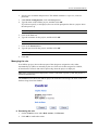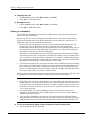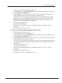
1
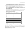
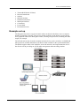
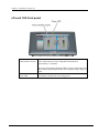
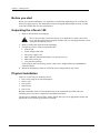
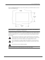
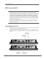
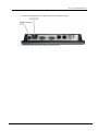
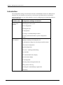
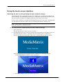
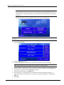
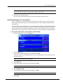
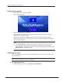
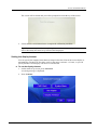
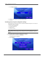
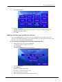
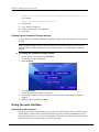
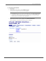
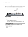
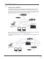
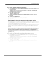
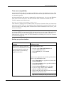
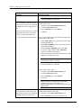
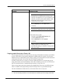
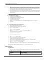
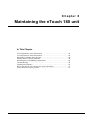
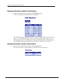
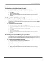
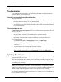
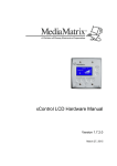
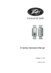
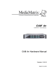
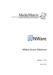
nTouch 180 Hardware Manual Version 1.7.2.0 March 27, 2015 Copyright notice The information contained in this manual is subject to change without notice. Peavey Electronics is not liable for improper installation or configuration. The information contained herein is intended only as an aid to qualified personnel in the design, installation and maintenance of engineered audio systems. The installing contractor or end user is ultimately responsible for the successful implementation of these systems. All creative content in this manual, including the layout, art design, content, photography, drawings, specifications and all other intellectual property is Copyright © 2015 Peavey Electronics Corporation. All Rights Reserved. Features & specifications subject to change without notice. All other registered trademarks or trademarks are the property of their respective owners. The ratc-server component is based in part on the work of the libwebsockets project: http://libwebsockets.org. Prepared by Peavey Digital Research, 6 Elm Place, Eynsham, Oxford, OX29 4BD, UK. Email:[email protected] (mailto:[email protected]). Scope This guide describes how to physically install an nTouch 180, connect it to a network and specify basic settings, ready to use it with NWare. ii Version 1.7.2.0 March 27, 2015 Contents Chapter 1 Important safety instructions................................................................ 1 Safety warnings ........................................................................................................................................2 Chapter 2 Before you start ..................................................................................... 5 Important network considerations ............................................................................................................6 Power outage and surge protection .........................................................................................................6 Warranty Registration ...............................................................................................................................6 Technical Support .....................................................................................................................................6 Thank You! ...............................................................................................................................................7 Chapter 3 Introduction to nTouch 180 .................................................................. 9 Description ..............................................................................................................................................10 Features..................................................................................................................................................10 Applications ............................................................................................................................................10 Example set up .......................................................................................................................................11 nTouch 180 front panel...........................................................................................................................12 nTouch 180 rear .....................................................................................................................................13 nTouch 180 side .....................................................................................................................................13 Chapter 4 Installing the unit ................................................................................. 15 Before you start ......................................................................................................................................16 Unpacking the nTouch 180.....................................................................................................................16 Physical installation ................................................................................................................................16 DHCP versus static IP ............................................................................................................................18 Connecting up the unit............................................................................................................................18 Chapter 5 Setting up the nTouch 180 unit ..........................................................21 Introduction .............................................................................................................................................22 Using the touch screen interface ............................................................................................................23 Using the web interface ..........................................................................................................................30 Chapter 6 Maintaining the nTouch 180 unit ....................................................... 47 Viewing hardware status information .....................................................................................................48 Viewing firmware status information .......................................................................................................48 Rebooting or shutting down the unit .......................................................................................................49 Adding entries to the log manually .........................................................................................................49 Restarting the ControlManager application ............................................................................................49 Troubleshooting ......................................................................................................................................50 Updating the firmware ............................................................................................................................50 Recovering the nTouch 180 unit if it stops functioning ...........................................................................51 Using advanced recovery options ..........................................................................................................51 Warranty statement .................................................................................................53 March 27, 2015 Version 1.7.2.0 iii Chapter 1 Important safety instructions In This Chapter Safety warnings................................................................................................. 2 March 27, 2015 Version 1.7.2.0 1 Chapter 1 - Important safety instructions . Safety warnings Warning: When using electrical products, basic cautions should always be followed, including the following: 1. 2. 3. 4. 5. 6. 7. 8. 9. 10. 11. 12. 13. 14. 15. 16. 17. 18. 2 Read these instructions. Keep these instructions. Heed all warnings. Follow all instructions. Do not use this apparatus near water. Clean only with a dry cloth. Do not block any of the ventilation openings. Install in accordance with manufacturer’s instructions. Do not install near any heat sources such as radiators, heat registers, stoves or other apparatus (including amplifiers) that produce heat. Do not defeat the safety purpose of the polarized or grounding-type plug. A polarized plug has two blades with one wider than the other. A grounding type plug has two blades and a third grounding plug. The wide blade or third prong is provided for your safety. If the provided plug does not fit into your outlet, consult an electrician for replacement of the obsolete outlet. Protect the power cord from being walked on or pinched, particularly at plugs, convenience receptacles, and the point they exit from the apparatus. Only use attachments/accessories provided by the manufacturer. Use only with a cart, stand, tripod, bracket, or table specified by the manufacturer, or sold with the apparatus. When a cart is used, use caution when moving the cart/apparatus combination to avoid injury from tip-over. Unplug this apparatus during lightning storms or when unused for long periods of time. Refer all servicing to qualified service personnel. Servicing is required when the apparatus has been damaged in any way, such as power-supply cord or plug is damaged, liquid has been spilled or objects have fallen into the apparatus, the apparatus has been exposed to rain or moisture, does not operate normally, or has been dropped. Never break off the ground pin. Write for our free booklet Shock Hazard and Grounding. Connect only to a power supply of the type marked on the unit adjacent to the power supply cord. If this product is to be mounted in an equipment rack, rear support should be provided. Control panel devices, including the xControl range, D series and nTouch 60, are designed for mounting in NEMA metal enclosures. Grounding to the front plate is required. Note for UK only: If the colors of the wires in the mains lead of this unit do not correspond with the terminals in your plug‚ proceed as follows: a) The wire that is colored green and yellow must be connected to the terminal that is marked by the letter E‚ the earth symbol‚ b) colored green or colored green and yellow. c) The wire that is colored blue must be connected to the terminal that is marked with the letter N or the color black. Version 1.7.2.0 March 27, 2015 nTouch 180 Hardware Manual d) The wire that is colored brown must be connected to the terminal that is marked with the letter L or the color red. 19. This electrical apparatus should not be exposed to dripping or splashing and care should be taken not to place objects containing liquids, such as vases, upon the apparatus. 20. The on/off switch in this unit does not break both sides of the primary mains. Hazardous energy can be present inside the chassis when the on/off switch is in the off position. The mains plug or appliance coupler is used as the disconnect device, the disconnect device shall remain readily operable. 21. Exposure to extremely high noise levels may cause a permanent hearing loss. Individuals vary considerably in susceptibility to noise-induced hearing loss, but nearly everyone will lose some hearing if exposed to sufficiently intense noise for a sufficient time. The U.S. Government’s Occupational Safety and Health Administration (OSHA) has specified the following permissible noise level exposures: Duration Per Day in Hours Sound Level dBA, Slow Response 8 90 6 92 4 95 3 97 2 100 1½ 102 1 105 ½ 110 ¼ or less 115 According to OSHA, any exposure in excess of the above permissible limits could result in some hearing loss. Ear plugs or protectors to the ear canals or over the ears must be worn when operating this amplification system in order to prevent a permanent hearing loss, if exposure is in excess of the limits as set forth above. To ensure against potentially dangerous exposure to high sound pressure levels, it is recommended that all persons exposed to equipment capable of producing high sound pressure levels such as this amplification system be protected by hearing protectors while this unit is in operation. SAVE THESE INSTRUCTIONS! March 27, 2015 Version 1.7.2.0 3 Chapter 2 Before you start In This Chapter Important network considerations ..................................................................... 6 Power outage and surge protection ................................................................... 6 Warranty Registration ....................................................................................... 6 Technical Support ............................................................................................. 6 Thank You! ....................................................................................................... 7 March 27, 2015 Version 1.7.2.0 5 Chapter 2 - Before you start . Important network considerations This product is designed to operate on a network backbone or infrastructure. The design, implementation and maintenance of this infrastructure is critical to correct operation and performance of the product. Peavey Electronics Corp does not support nor service network cabling, hubs, switches, patch bays, wall plates, connector panels or any other type of network interconnect device. Please ensure that these components and their associated installation techniques have been properly designed and installed for audio and network applications. Power outage and surge protection We make the following recommendations for the power source: Use an uninterruptable power supply (UPS) to protect against power outages. Use a power surge protection device, such as a Surge-X (http://www.surgex.com). This provides protection from destructive spikes, surges and inductive transients. Warranty Registration Please take a few minutes and fill out the warranty registration card. Although your warranty is valid without the registration, the information you provide with the form is crucial to our support group. It enables us to provide better service and customer support, and to keep you informed of new product updates. Tip: Refer to the warranty statement at the rear of this manual for details of what your warranty includes and what the limitations are. Technical Support When you require assistance with your product, you can get help from several sources. Apart from the online Knowledge Center, there are many technical documents, white papers and application notes on our website and on other websites on the Internet, covering subjects including Python programming, SNMP and serial control. If you cannot find the information you require, contact your dealer or distributor. If you are still unable to solve the issue, you can contact us directly using the details below. MediaMatrix has an extensive Technical Services Group that provides technical support, repair and implementation services. Peavey Electronics Corp., MediaMatrix Division, 5022 Hartley Peavey Drive, Meridian, MS 39305, USA. Phone: 601.483.9548 Phone (toll free): 866.662.8750 Fax: 601.486.1678 Website: http://mm.peavey.com (http://www.peaveycommercialaudio.com/). 6 Version 1.7.2.0 March 27, 2015 nTouch 180 Hardware Manual Thank You! Thank you for purchasing this MediaMatrix product. It is designed to provide years of trouble-free operation and high quality performance. We are confident that you will find this product and other MediaMatrix products to be of the highest quality. March 27, 2015 Version 1.7.2.0 7 Chapter 3 Introduction to nTouch 180 In This Chapter Description ........................................................................................................ 10 Features ............................................................................................................. 10 Applications ...................................................................................................... 10 Example set up .................................................................................................. 11 nTouch 180 front panel ..................................................................................... 12 nTouch 180 rear ................................................................................................ 13 nTouch 180 side ................................................................................................ 13 March 27, 2015 Version 1.7.2.0 9 Chapter 3 - Introduction to nTouch 180 . Description nTouch 180 is a touch screen control panel for controlling MediaMatrix systems. The device runs an embedded version of NWare Kiosk and allows the user to control a project designed in NWare. In addition to this functionality, nTouch 180 runs ControlManager application software. ControlManager provides a platform for MediaMatrix control systems. It can be custom configured to monitor and control multiple NWare projects, consisting of NIONs, CABs, amplifiers, and other devices. Additionally, it can also monitor and control 3rd party devices using SNMP and execute Python scripts. nTouch 180 supports RATC and PASHA protocols, allowing you to interact with an NWare project via an Ethernet or serial connection. nTouch 180 provides several mounting options, including surface, panel, flush and general VESA mounting. Notes: nTouch 180 units host projects for control and monitoring, but do not have any DSP capability. Using all the capabilities of nTouch 180 requires a firm understanding of NWare, SNMP and Python scripting. Features Touch screen user interface Runs Kiosk for control of NWare projects (hosted by the nTouch 180 or other MediaMatrix devices on the network) Supports SNMP, RATC, Python Allows control using different protocols over Ethernet or serial connections 1.6G single core atom processor Two serial ports 2 Gigabytes of media storage Standard VESA mount Easy connection and installation Software upgradable from within NWare or via a USB stick Low power requirements Cost effective. Applications 10 Conference rooms Meeting rooms Ballrooms Hospitality and hotel meeting rooms Paging systems Entertainment systems Version 1.7.2.0 March 27, 2015 nTouch 180 Hardware Manual Theater BOH (Back of House) Bars and restaurants Schools Medical facilities Institutional facilities Municipal facilities Courtrooms Lecture halls Presentation rooms. Example set up The diagram below shows a typical scenario where an nTouch 180 allows users to control a number of amplifiers remotely. The project created in NWare on the laptop gives the Kiosk users graphical controls for altering the volume, selecting an input source, or muting the audio output, for example. The nTouch 180 can also be used to monitor network devices, such a switches, via SNMP and other protocols, and this information can then be made available to the system administrator. The NION supplies audio to the amplifiers across the network, and complements the role of the nTouch 180 in providing an overall audio management and networking solution. March 27, 2015 Version 1.7.2.0 11 Chapter 3 - Introduction to nTouch 180 nTouch 180 front panel Touch-sensitive screen Color, touch-sensitive screen. Diagonal measurement is approximately 7" (180mm). The screen is designed to display NWare projects with buttons and other controls large enough for the user to gesture using a finger or stylus. Power LED 12 Lit when the nTouch 180 is receiving power. Version 1.7.2.0 March 27, 2015 nTouch 180 Hardware Manual nTouch 180 rear VESA bracket mounting hole The four holes are used to fix the nTouch 180 to a VESA bracket using the supplied screws. nTouch 180 side March 27, 2015 Version 1.7.2.0 13 Chapter 3 - Introduction to nTouch 180 Power connector socket 12V DC power connector. On/off switch Switches the unit on and off. Note: Settings in the BIOS will power up the unit automatically as soon as it receives power. Serial ports Male DB-9 connectors for RS-232 serial communications. Ethernet ports 0 and 1 Standard RJ-45 connector that accepts a network data cable for data transport to/from the internal network interface. A connection is required to one of the two Ethernet ports. Note: The unit does not support Power over Ethernet. 14 USB ports For connecting a USB stick for unit recovery. Reset button Performs a hard reboot of the nTouch 180. Version 1.7.2.0 March 27, 2015 Chapter 4 Installing the unit In This Chapter Before you start ................................................................................................. 16 Unpacking the nTouch 180 ............................................................................... 16 Physical installation .......................................................................................... 16 DHCP versus static IP ....................................................................................... 18 Connecting up the unit ...................................................................................... 18 March 27, 2015 Version 1.7.2.0 15 Chapter 4 - Installing the unit . Before you start Before you start the installation, it is important to consider the implications for your network and power supply system. The infrastructure must be designed and installed correctly, in order to provide reliable and error-free performance. Unpacking the nTouch 180 1. Remove the unit from its packaging. The LCD screen has a protective plastic cover attached to it. Only remove this cover after the unit has been properly installed. The cover helps protect the screen during the installation process. 2. Remove all the other items from the packaging. 3. Check that you have all the items listed below: nTouch 180 Power adapter with cable IEC power supply cord Blue USB stick labeled MediaMatrix for system recovery Blue touch screen pen User literature package. If any of these items are missing, please contact your Authorized Peavey MediaMatrix contractor/dealer. 4. Retain the packaging. It must be used if the unit is transported for any reason. Physical installation There are several ways to mount the device: Into a wall, using an in-wall mounting kit Onto a wall Into a panel Onto an arm Into a rack. Read the remainder of this section and then refer to the instructions provided with your mounting device in order to complete the installation procedure. The unit uses a standard 75mm VESA mount. Ensure that you use an appropriate bracket and appropriate screws for this type and size of mount. 16 Version 1.7.2.0 March 27, 2015 nTouch 180 Hardware Manual If you are mounting the unit into a cavity, such as a panel, you will need to make a cut out as shown in the diagram below. Note: It important to use appropriate mounting hardware. For example, when attaching to a drywall, use screws with wall fixings, rather than nails. The nTouch 180 requires 12VDC power. Each unit is shipped with a power supply capable of 12VDC at 3A max (36W max). You can choose to power the nTouch 180 locally by placing this power supply near to it, or you can power the unit remotely with an industrial 12VDC power supply. When connecting an external power supply, note that the plug is wired with the ground on the sleeve of the barrel and the +12VDC connected to the center pin. The warranty does not cover issues caused by power supply polarity reversal. We recommend that two people complete the installation, to ensure that the unit does not get damaged, particularly when it is mounted in a position where it may fall. Do not block any of the ventilation openings. Note: Do not turn the unit on until instructed to do so later in this manual. March 27, 2015 Version 1.7.2.0 17 Chapter 4 - Installing the unit . DHCP versus static IP Notes: Care should be taken when choosing to use Dynamic Host Configuration Protocol (DHCP), rather than a static IP address. DHCP mode is provided as a convenience when using units in informal settings or for test purposes. A static IP address should always be used when units are deployed in end-user installations. DHCP-obtained IP addresses depend on a lease to be maintained by the DHCP server in order to keep an assigned IP address. If the IP address lease is allowed to expire, there is a chance that the IP address assigned to one or more units could be lost, changed or reassigned, resulting in the loss of control or audio from a project. The network administrator should be able to give you a range of static (or fixed) IP addresses to use for your project. When requesting these IP addresses, be sure to obtain enough to cover each unit. Connecting up the unit 1. On the side of the unit, insert an Ethernet cable into one of the Ethernet ports, then connect the other end of the cable to a local Ethernet switch. The nTouch 180 unit is configured to connect to a DHCP server to obtain an IP address and network settings. If it cannot find a DHCP server, an IP address starting with 169 will be used. 2. If you are using serial connections, connect the serial cables to the serial ports. 18 Version 1.7.2.0 March 27, 2015 nTouch 180 Hardware Manual 3. Connect the supplied power cable to the power connector socket. 4. Connect the other end of the cable to a power source. March 27, 2015 Version 1.7.2.0 19 Chapter 5 Setting up the nTouch 180 unit In This Chapter Introduction ....................................................................................................... 22 Using the touch screen interface ....................................................................... 23 Using the web interface .................................................................................... 30 March 27, 2015 Version 1.7.2.0 21 Chapter 5 - Setting up the nTouch 180 unit . Introduction The configuration settings for an nTouch 180 unit are distributed between two different user interfaces: the web interface (accessed via a web browser) and the touch screen interface. Check the table below to see which interface to use for configuring and controlling different features of the unit. Interface name Configuration settings and actions Touch screen interface Calibrating the touch screen Kiosk configuration Restarting the unit IP configuration Accessing a Command Prompt window Specifying advanced Windows system configuration settings Web interface Stopping, restarting and erasing the role IP configuration settings for network ports and host name CAB control configuration Pandad configuration FTP server - enabling and disabling Time and date CPU load and PSU status display Firmware status display User management Rebooting and powering down the unit Adding entries to the log Restarting the ControlManager application Redundancy 22 Version 1.7.2.0 March 27, 2015 nTouch 180 Hardware Manual Using the touch screen interface Switching the unit on and specifying the basic network settings The nTouch 180 unit is configured to connect to a DHCP server to obtain an IP address and network settings. If it cannot find a DHCP server, an IP address starting with 169 will be used. The current network settings are displayed at the top of the main set up screen. If you want to use DHCP, you do not need to change the network set up, but it is important that you check that the network to which you are connecting the unit has a DHCP server. Note: If DHCP mode is selected, but there is no DHCP server on the network, the unit will be unable to communicate with other devices. To switch the unit on and specify the basic network settings 1. Power up the unit. The unit will start up as soon as it receives power. 2. Check that the green power LED is lit on the front of the unit above the display. If it is not, check that the power cable is connected to the unit and the power is switched on. The unit will start up automatically. This screen is displayed during the boot process. If the nTouch 180 has been configured with a username for connecting to Kiosk: The Starting Kiosk countdown screen is displayed. March 27, 2015 Press Run Setup to display the main set up screen. Version 1.7.2.0 23 Chapter 5 - Setting up the nTouch 180 unit Note: If you let the counter reach zero, Kiosk will start automatically. If you have a keyboard connected, you can press ALT+F4 to display the Starting Kiosk screen. If you do not have a keyboard connected, you will need to reboot the unit to access the set up screen. If no username has been specified, the main set up screen is displayed. Tip: The Exit button is only available on the main set up screen if a project name has been specified. 3. Press Network Setup. 4. Clear the DHCP check box. 5. Touch the IP Addr box, then type an IP address using the on-screen keyboard. Note: The IP address must be unique on the network to avoid conflicts. 6. If your subnet is connected to a router, specify the router's IP address in the Gateway box. If you have no router, leave the Gateway box blank. 7. Type the network mask in the Subnet box. 8. If you intend to use a domain name to identify the nTouch 180 on the network, e.g. nTouch180-mainroom.mediamatrix.corpname.net, type the IP address of a DNS in the DNS box. 9. Press OK. 24 Version 1.7.2.0 March 27, 2015 nTouch 180 Hardware Manual Note: When you exit the Network Setup screen, you will be prompted to restart the system. This must be done in order for the settings to take effect. 10. Press Yes to restart the system. The nTouch 180 will reboot and the new network settings will take effect. Specifying settings for running Kiosk If you want Kiosk to start automatically when the nTouch 180 boots up, you must specify a project name (and optionally, a user name and password). These settings will then be used automatically. A project name is also required if you want to start Kiosk manually by exiting the main set up screen in the touch screen interface. If you specify the project using the touch screen interface, the Exit button will be available immediately. If you use the web interface, you must firstly display the project settings in the touch screen interface, then select Exit to refresh the display. To specify settings for running Kiosk automatically 1. On the main set up screen, press Project. 2. Press Edit Project. 3. Type the name of the NWare project, and then click OK. If you do not specify a valid project, the user will be prompted to choose a project when the unit powers up. Note: The project name is case-sensitive. 4. Press Edit User. 5. Type the username for the project, and then click OK. Note: The username is case-sensitive. 6. Press Edit Password. 7. Type the password for the project, and then click OK. Note: The password is case-sensitive. 8. Press Exit. March 27, 2015 Version 1.7.2.0 25 Chapter 5 - Setting up the nTouch 180 unit Starting Kiosk manually 1. On the main set up screen, press Exit. This screen is displayed. 2. Wait for the countdown to reach zero. Kiosk will start automatically and attempt to connect to an NWare project using the settings that are currently stored. If the project settings are valid, the project start screen will be displayed in Kiosk. If the project name or log on settings are not valid, you will be prompted to enter them before you can continue. Tips: The Starting Kiosk... screen will now be shown each time the nTouch 180 boots. If you want to exit Kiosk when it is running, you will need to use a keyboard connected to the nTouch 180. Press ALT+F4 to close the application and return to the Starting Kiosk... countdown screen. Calibrating the screen If you find that the touch screen is not responding when you try to select on-screen options, you can calibrate it. Tip: We recommend that you use a stylus when completing the procedure below, as you will need to touch areas of the screen very accurately. To calibrate the screen 1. On the main set up screen, press Touch Screen Calibration. 26 Version 1.7.2.0 March 27, 2015 nTouch 180 Hardware Manual The screen will be cleared and you will be prompted to touch the top of the screen. 2. Follow the on-screen instructions to complete the calibration procedure. Tip: If you want to quit without completing the procedure, stop pressing the screen, and after a short delay the main set up screen will be displayed. Setting the display timeout You can specify the length of time that must elapse before the nTouch 180 screen display is automatically switched off. The delay can be in the range 2 minutes - 12 hours, or you can specify that the screen display will never be switched off. To set the display timeout 1. On the main set up screen, press Advanced. A warning message is displayed. 2. Press Continue. March 27, 2015 Version 1.7.2.0 27 Chapter 5 - Setting up the nTouch 180 unit 3. Press Display Timeout. 4. Press the + and - buttons to specify the timeout delay. 5. Press Set. Specifying advanced system configuration settings The nTouch 180 runs Microsoft Windows Embedded Standard and supports a wide range of configuration options, including: Device driver management Event log management Remote access Windows firewall. Note: Changing settings can have adverse affects on the operation of the unit, so it is very important that you only change them when instructed to do so by MediaMatrix Technical Support. To specify advanced system configuration settings 1. On the main set up screen, press Advanced. A warning message is displayed. 2. Press Continue. 28 Version 1.7.2.0 March 27, 2015 nTouch 180 Hardware Manual 3. Press System Menu. 4. Change the settings. You can refer to the Windows Help and Support Center on a Windows XP PC for information on the settings. 5. Press Exit. Making a new time zone available for selection If you are installing nTouch 180 units in a time zone that is not listed on the Time and Timezone tab of the web interface, you will need to add a new entry for the time zone to the timezones_lut.txt file on the nTouch 180 unit. To add a new mapping to the time zone configuration file 1. On the main set up screen, press Advanced. You will be asked to confirm your choice. 2. Press Continue. The Advanced Functions screen is displayed. 3. Press System Menu. 4. Press Explorer. Windows Explorer is displayed. 5. Browse to C:\nControl\ncontrol_data. 6. Open the timezones_lut.txt file. 7. Add a new entry to the end of file using this format: March 27, 2015 Version 1.7.2.0 29 Chapter 5 - Setting up the nTouch 180 unit <Windows time zone>|<Linux time zone continent>/<Linux time zone city> For example: Eastern Standard Time|America/New_York 8. 9. 10. 11. Save the file. Close Windows Explorer. On the System menu, press Restart. Click Yes. Displaying the Command Prompt window You can display a standard Windows Command Prompt window and then type in commands directly. Note: Changing settings can have adverse affects on the operation of the unit, so it is very important that you only change them when instructed to do so by MediaMatrix Technical Support. To display the Command Prompt window 1. On the main set up screen, press Advanced. A warning message is displayed. 2. Press Continue. 3. Press CMD Shell. A Command Prompt window is displayed. 4. Perform the actions you have been instructed to perform by MediaMatrix Technical Support. 5. When you have finished, type Exit. Using the web interface Starting the web interface The procedure below assumes that you are going to start the nTouch 180 web interface from within NWare, which locates and lists all nTouch 180 units and other MediaMatrix devices, automatically. However, if you know the IP address of the unit, you can type it directly into the location field of your browser, and you will be connected. 30 Version 1.7.2.0 March 27, 2015 nTouch 180 Hardware Manual To start the web interface 1. Start NWare. 2. At the bottom of the window, click the Remote Log tab. A list of devices on the local network will be displayed. Tips: If the Remote Log tab is not visible, on the View menu, click Show Output frame. If no devices are listed, Pandad may not be running. Refer to Troubleshooting in Pandad Administrator Guide for more information. 3. Right-click the nTouch 180 unit, and then click Launch Web Interface. If the connection is successful, the following screen is displayed. March 27, 2015 Version 1.7.2.0 31 Chapter 5 - Setting up the nTouch 180 unit Specifying the network settings Network ports Before you specify network settings, make sure you know which physical interfaces at the side of the nTouch 180 unit Local Area Connection and Local Area Connection 2 on the Network screen correspond to. Setting the IP address Using DHCP to assign an IP address automatically 1. Confirm that the network to which you are connecting the unit has a DHCP server. Notes: If DHCP mode is selected, but there is no DHCP server on the network, the unit will be unable to communicate with other devices. In this example, the DHCP server is provided by the router. Ensure that your network is using a router. A plain switch will not provide the required DHCP server for the example. 2. Navigate to the Network screen. 3. Under Local Area Connection x (where x is the interface number), in the IP Configuration Method list, click DHCP. 4. Click Set to confirm the action. You will be asked to log on. 5. Specify your username and password. The default username is superuser; it has no password. 32 Version 1.7.2.0 March 27, 2015 nTouch 180 Hardware Manual . Using a static IP address 1. Navigate to the Network screen. 2. Under Local Area Connection x (where x is the interface number), in the IP Configuration Method list, click static. 3. Click Set to confirm the action. You will be asked to log on. 4. Specify your username and password. The default username is superuser; it has no password. Further options will be displayed. 5. In the IP box, type an IP address. Note: The IP address must be unique on the network to avoid conflicts. 6. In the Netmask box, type the network mask for your network. 7. If your subnet is connected to a router, specify the router's IP address in the Gateway box. If you have no router, set Gateway to none. 8. If you intend to use a domain name to identify the nTouch 180 unit on the network, e.g. www.my_nTouch 180.com, specify the IP address of a DNS on the network, which will resolve the name to an IP address. 9. Click Set to confirm the action. Specifying a name for the nTouch 180 unit You can specify a name for the nTouch 180 unit that will identify it in NWare and will also be shown in the web interface. To specify a name for the nTouch 180 unit 1. On the Network screen, in the Host Name box, type a name for the nTouch 180 unit. The name can only contain letters and numbers, and cannot contain spaces. The maximum length permitted is 12 characters. 2. Click Set to confirm the action. You will be asked to log on. 3. Specify your username and password. The default username is superuser; it has no password. March 27, 2015 Version 1.7.2.0 33 Chapter 5 - Setting up the nTouch 180 unit Interfacing with a CAB device The nTouch 180 unit can interface with CAB devices, including the CAB 4n. This in turn allows control of external devices via the GPIO port, relays, RS-485 port etc. on the CAB. The nTouch 180 unit has two Ethernet ports, allowing a number of different configurations. In the example below, the nTouch 180 unit can communicate with the CAB via the first of its two Ethernet ports, labeled Local Area Connection in the web interface. In the next example, in order to communicate with the CAB, data must be sent via the second Ethernet port, labeled Local Area Connection 2 in the web interface. You need to specify which Ethernet port is to be used for communicating with CAB devices on the network. 34 Version 1.7.2.0 March 27, 2015 nTouch 180 Hardware Manual To specify a network interface for CAB control 1. On the Network screen, under CAB Control Interface, select a network interface for the CobraNet network. The details for the Local Area Connection interface are shown first, followed by the details for Local Area Connection 2. 2. Click Set to confirm the action. You will be asked to log on. 3. Specify your username and password. The default username is superuser; it has no password. 4. Navigate to the Special screen. 5. Under Unit Shutdown in the action list, click reboot. 6. Click Do it. Specifying an IP address for connecting to other network devices The Pandad Windows service that runs on the NWare PC will detect the nTouch 180 unit using a specified IP address and make it available in NWare. This IP address will also be used to connect to other MediaMatrix devices on the network. The nTouch 180 motherboard is fitted with two Ethernet ports. If both ports are used, two IP addresses will be used. You will therefore need to specify which IP address to advertise to Pandad. If you have specified the IP addresses manually via the web interface, they will be displayed under Local Area Connection and Local Area Connection 2 on the Network page. If you are using DHCP, you will need to ask your systems administrator to look at the DHCP configuration for your network to see how addresses have been allocated to interfaces on the nTouch 180 unit. To specify an IP address for connecting to other network devices 1. On the Network screen, under Panda Interface, select an IP address to advertise to Pandad on the control network. The details for the Local Area Connection interface are shown first, followed by the details for Local Area Connection 2. 2. Click Set to confirm the action. You will be asked to log on. 3. Specify your username and password. The default username is superuser; it has no password. March 27, 2015 Version 1.7.2.0 35 Chapter 5 - Setting up the nTouch 180 unit . Setting the time and date Introduction For accurate reporting of events when running different MediaMatrix units, it is critical to specify the proper time zone, time, and date settings. Correct settings will ensure that the event logs and other time sensitive information are accurately recorded and displayed. There is a time synchronization system that ensures that the time and date settings on NIONs, nControl units and nTouch 180 units are the same across the control network. If you change the date on a NION, for example, it is automatically changed on the other devices. This feature is especially useful for debugging. If you look at an event in the log that occurred at a particular time on one NION, you can be sure that an event with the same timestamp on a different NION occurred at exactly the same time. You can specify the time and date settings manually, or they can be obtained automatically from a time server. Tip: A time server can be set up on your local network, or you can connect to one via the internet. For information on available internet time servers, see http://www.pool.ntp.org (http://www.pool.ntp.org). Synchronization modes Mode name Description Normal If you specify Normal mode for all units on the network, so no Master node is available, when you specify time and date settings on any of the units, they will be assigned to the others automatically. If a unit on the network is using Time Server or Master mode, all units in Normal mode will be assigned time and date settings from that unit – they will act as slaves. Master The time and date settings from this unit will be assigned to all units that are using Normal mode. Time Server This node will contact a time server to retrieve time and date settings. The time and date settings from this unit will be assigned to all units that are using Normal mode. The time server can be contacted using its IP address or a domain name. Note: When you use a domain name, it must be resolved to an IP address. This is done automatically, but you must specify DNS or DHCP settings on the Network screen in the web interface. 36 Version 1.7.2.0 March 27, 2015 nTouch 180 Hardware Manual Time zone compatibility nControl and nTouch 180 units run Microsoft Windows, whereas the NION uses Linux. This means there are compatibility considerations for automatic time synchronization between the two operating systems. nControl and nTouch 180 units use a mapping file, called timezones_lut.txt, to map Windows time zones to Linux time zones. This file is located on the nControl or nTouch 180 unit. The file contains entries like this one: Eastern Standard Time|America/New_York This declares a mapping from a Windows time zone (Eastern Standard Time) to a Linux time zone (America/New_York). So, for example, if an nControl unit is set up as the time server, the Eastern Standard Time setting on the nControl unit would be translated to America/New_York on the slave NIONs. Note: The mapping file contains a comprehensive list of time zones for both systems, but it is possible that NION, nControl and nTouch 180 units are being run in a part of the world which uses a time zone that is not in the mapping file. In this case, you will need to add a new mapping for the local time zone. For more information, see Making a new time zone available for selection (on page 29). Setting up synchronization Scenario Actions to take You want to be able to set the time and date on any MediaMatrix node on the network manually, and for the settings to then be automatically assigned to the others. On all MediaMatrix nodes: 1. Navigate to the Time and Timezone tab. 2. Clear the Time Server box. 3. In the Authority list, click normal. 4. Click Set. If you want to adjust the time and date, perform these steps on any MediaMatrix node: 1. In the Time (24hr) box, type the new time in the format HH:MM:SS. 2. In the Date (mm/dd/yy) box, type the new date in the format mm/dd/yy. 3. Under the Date (mm/dd/yy) box, click Set. 4. If you are using a NION, under Timezone, specify a continent and country. 5. If the country has more than one time zone, in the Zone list, click the time zone. Tip: Where a country has only one time zone, you March 27, 2015 Version 1.7.2.0 37 Chapter 5 - Setting up the nTouch 180 unit Scenario Actions to take do not need to make a selection. 6. Under the Zone box, click Set. You want the time and date for all nodes on the network to be obtained automatically from a single, master unit. On the master node: 1. Navigate to the Time and Timezone tab. 2. Clear the Time Server box. 3. In the Authority list, click Master. You do not want anyone to be able to 4. Click Set. assign times and dates to the other units by accessing them directly. You will specify the time manually. If you want to adjust the time and date, perform these steps on the master node: 1. In the Time (24hr) box, type the new time in the format HH:MM:SS. 2. In the Date (mm/dd/yy) box, type the new date in the format mm/dd/yy. 3. Under the Date (mm/dd/yy) box, click Set. 4. If you are using a NION, under Timezone, specify a continent and country. 5. If the country has more than one time zone, in the Zone list, click the time zone. Tip: Where a country has only one time zone, you do not need to make a selection. 6. Under the Zone box, click Set. On the other (slave) nodes: 1. Navigate to the Time and Timezone tab. 2. Clear the Time Server box. 3. In the Authority list, click normal. 4. Click Set. Note: If you try to change the time and date settings on the slave nodes, they will automatically change to match the settings on the master node. a) You want the time and date for all nodes on the network to be obtained automatically from a time server. 38 Version 1.7.2.0 On the master (time server) node: 1. Navigate to the Time and Timezone tab. 2. In the Time Server box, type IP address or March 27, 2015 nTouch 180 Hardware Manual Scenario Actions to take domain name of a time server. Note: If you are using a domain name to contact the time server, a DNS must be present on the network. If a DHCP server is not available on the network, you must specify the IP address of the DNS on the Network page for the local area connection you are using. 3. In the Authority list, click time server. 4. Click Set. Note: Once you select time server mode, you will not be able to change the time or date settings. On the other (slave) nodes: 1. Navigate to the Time and Timezone tab. 2. Clear the Time Server box. 3. In the Authority list, click normal. 4. Click Set. Note: If you try to change the time and date settings on the slave nodes, they will automatically change to match the settings on the time server node. Copying media files to the nTouch 180 You can copy media files over to the nTouch 180 using FTP and then use them in your NWare projects. This allows you to quickly change the available media in a project. You can also minimize the size of the NWare project file by storing your media on the nTouch 180 and not in the project file itself. You can use any FTP client to copy the files. In order to allow files to be copied, you need to enable the FTP server on the node you are using. This is done via the web interface. Once FTP is enabled, you can use an FTP client (or the FTP command from a Command Prompt window) to copy files over. Files on an nControl unit can be played using a Media Player device in your NWare design. Files on a NION can be played using a Wave File Player device in your NWare design. For more information on these devices, refer to the NWare Device Reference. Notes: It is not currently possible to view the amount of available space for storing media files. March 27, 2015 Version 1.7.2.0 39 Chapter 5 - Setting up the nTouch 180 unit When the project is deployed, media files must be located on the same node that hosts the NWare device playing the files. If the files are located on a different node, you will not be able to play them. We recommend that you manually assign the device playing the files to a role and deploy that role to the node that will host the media files. You can disable the FTP server by clearing the FTP check box (see procedure below), but if you are using an nControl unit or nTouch 180 unit, you must restart it before the change will take effect. To enable the FTP server 1. Navigate to the Network screen. 2. Under Services, select the FTP check box. 3. Click Set to confirm the action. You will be asked to log on. 4. Specify your username and password. The default username is superuser; it has no password. To copy media files to the nTouch 180 1. Open a Command Prompt window. 2. Navigate to the folder containing the media files. 3. Type FTP and press Enter. The ftp> prompt is displayed. 4. Type open <IP address of nTouch 180> and press Enter. The following message is displayed. Connected to <IP address>. ... User (<IP address>:(none)): 5. Type anonymous and press Enter. 6. If you are prompted for a password, press Enter. You do not need to specify a password. 7. If you want to list the files already copied to the unit, type ls and press Enter. 8. Type binary to switch to binary copy mode. 9. Type mput <filename> and press Enter. The parameter <filename> is either a single file or a wildcard referencing multiple files. When you have finished copying files, type quit to close the ftp session. Managing users Introduction Users are created via the web interface, and assigned privileges to allow them to perform certain operations, as listed below. 40 Privilege What it controls Deploy Determines whether the user can deploy a role to this node. Version 1.7.2.0 March 27, 2015 nTouch 180 Hardware Manual Update Firmware Determines whether the user can update the firmware on this node. Debug Menu Access Determines whether the user can access the debug menu of this node using the Pandebug application. User Administration Determines whether the user can create, edit and remove user accounts on this node. NioNode Administration Access Determines whether the user can change settings such as network configuration and time and date. Log Access Determines whether the user can view or clear the log. Tip: For more information on viewing the log within NWare, see Remote Log in the NWare User Guide. There are two default users: superuser and defaultuser, which cannot be deleted. You can add your own users as necessary. superuser Has all privileges enabled. None of its settings can be changed, apart from the password, which is blank by default. defaultuser Has all privileges enabled, apart from User Administration and NioNode Administration Access. In NWare, when you perform an action that involves the node, such as deploying a role or updating firmware, NWare logs on to the node using a particular username. The node matches this username with the username of the same name stored on the unit. The privileges of the username on the node determine whether the action may be carried out. Tip: Users often log on to nodes with the username defaultuser. If the settings for this username on the node show the Deploy privilege set to Disallow, it will not be possible to deploy a role to the node even when they are logged on. Adding a new user 1. Navigate to the User Management screen in your web browser. 2. Click Add new user. The Edit User screen is displayed. 3. In the user name box, type the name of the new user. 4. If you want to specify a password for the user, which must be specified when the user logs on, type the password in the Password box, and then type the password again in the Confirm box. Note: We recommend that you always specify a password for users to ensure unauthorized persons do not gain access to the node. 5. Specify the user privileges. March 27, 2015 Version 1.7.2.0 41 Chapter 5 - Setting up the nTouch 180 unit Privilege What it controls Deploy Determines whether the user can deploy a role to this node. Update Firmware Determines whether the user can update the firmware on this node. Debug Menu Access Determines whether the user can access the debug menu of this node using the Pandebug application. User Administration Determines whether the user can create, edit and remove user accounts on this node. NioNode Administration Access Determines whether the user can change settings such as network configuration and time and date. Log Access Determines whether the user can view or clear the log. Tip: For more information on viewing the log within NWare, see Remote Log in the NWare User Guide. 6. Click Apply. Deleting a user You can delete users from a node when they are no longer required. Note: You cannot delete defaultuser or superuser. To delete a user 1. Navigate to the User Management screen in your web browser. 2. Click the Delete button next to the user you want to delete. You will be asked to confirm the delete operation. 3. Click Yes. Specifying settings for running Kiosk If you want Kiosk to start automatically when the nTouch 180 boots up, you must specify a project name (and optionally, a user name and password). These settings will then be used automatically. A project name is also required if you want to start Kiosk manually by exiting the main set up screen in the touch screen interface. If you specify the project using the touch screen interface, the Exit button will be available immediately. If you use the web interface, you must firstly display the project settings in the touch screen interface, then select Exit to refresh the display. To specify settings for running Kiosk 1. Navigate to the User Management tab. You will be asked to log on. 42 Version 1.7.2.0 March 27, 2015 nTouch 180 Hardware Manual 2. Specify your username and password. The default username is superuser; it has no password. 3. Under Kiosk Configuration, click in the Project box. 4. Type the name of the NWare project, and then click OK. If you do not specify a valid project, the user will be prompted to choose a project when the unit powers up. Note: The project name is case-sensitive. 5. Click in the User box. 6. Type the username for the project, and then click OK. Note: The username is case-sensitive. 7. Click in the Password box. 8. Type the password for the project, and then click OK. Note: The password is case-sensitive. 9. Click Set. Managing the role In an NWare project, devices that are part of the design are assigned to roles, either automatically by NWare or manually by the user. Each role is then assigned to a NION, nControl unit or nTouch 180 unit for processing when the project is deployed. Tip: Once a project has been deployed to a node, if the node is power cycled, the project is restarted automatically. The Control screen shows the NWare project to which the role belongs, the name of the role and how long it has been loaded. Restarting the role 1. On the Control screen, under Role Actions, click Restart. 2. Click OK to confirm the action. March 27, 2015 Version 1.7.2.0 43 Chapter 5 - Setting up the nTouch 180 unit Stopping the role 1. On the Control screen, under Role Actions, click Halt. 2. Click OK to confirm the action. Erasing the role 1. On the Control screen, under Role Actions, click Erase. 2. Click OK to confirm the action. Setting up redundancy The nTouch 180 redundancy system allows a standby unit to replace an active unit on the network if it stops functioning. When the system is used, the configuration settings from the active unit are automatically copied to the standby unit to keep them synchronized. The two units are responsible for a single role. There are two main modes of operation: One nTouch 180 is the primary unit and a second nTouch 180 is the backup unit. The primary unit is active and the backup unit is in standby mode. The backup unit continuously monitors the primary unit and synchronizes its files with the primary unit. In the event the primary unit fails, the backup unit will take over. If the primary unit starts functioning, it will take over from the backup unit. This mode is recommended when you want to prioritize the use of one unit over another. The primary unit may have a serial device attached, for example, and you want this device to be available to your project whenever possible. If a switchover is made to the backup unit, but then the primary unit subsequently starts functioning, you want to switch back to the primary unit immediately, so the serial device can be used. Two nTouch 180 units are set up as peers. One unit is active and the other unit is in standby mode. The unit in standby mode continuously monitors the active unit and synchronizes its files with the active unit. In the event the active unit fails, the unit in standby mode will take over. If the failed unit comes back online, it will run in standby mode and monitor the active unit, ready to take over if there is another failure. If Kiosk users are connected to a project hosted on an nTouch 180 unit when it fails, they will be automatically connected to the project on the backup unit after a short delay. Notes: By default, when one nTouch 180 unit takes over from another, the controls in the project (knobs, faders etc.) are reset to their default values. If you would like the controls to be set to the most recent values displayed in Kiosk, you need to change a setting in NWare: On the NWare File menu, click Project Properties, click Advanced, and then select the Auto save settings check box. It is important that you test the redundancy system carefully before using it in an installation. If the switchover to the standby unit does not work, users will be unable to connect to the NWare project. You can set up a redundancy system to use an nControl unit and an nTouch 180 unit, rather than units of the same type. However, the NWare project must be fully compatible with both units, otherwise it will not function properly when the backup unit takes over. To set up redundancy when using a primary unit and a backup unit 1. Power up both the nTouch 180 units. 44 Version 1.7.2.0 March 27, 2015 nTouch 180 Hardware Manual 2. Connect to the web interface on the backup unit. 3. On the Special screen, under Redundancy, type the IP address of the primary nTouch 180 unit in the Peer Unit Address box. 4. In the Timeout box, type the number of seconds to wait after the backup unit has lost contact with the primary unit before the backup unit takes control. Waiting for a period of time allows the primary unit to start and load the project after a normal power cycle, preventing the backup unit from taking over automatically. It also allows for when communications between the primary and backup unit stop for a few seconds because of a slow network, for example. 5. Click Set to confirm the action. You will be asked to log on. 6. Specify your username and password. The default username is superuser; it has no password. 7. Restart the backup nTouch 180 unit. To set up redundancy when using two units as peers 1. Power up both the nTouch 180 units. 2. Connect to the web interface on the first unit. 3. On the Special screen, under Redundancy, type the IP address of the second nTouch 180 unit in the Peer Unit Address box. 4. In the Timeout box, type the number of seconds to wait after this unit has lost contact with the other unit before this unit takes control. The same value can be specified on both units. This is because if they both start at the same time, they will negotiate to determine which unit will be active and which will operate in standby mode. 5. Click Set to confirm the action. You will be asked to log on. 6. Specify your username and password. The default username is superuser; it has no password. 7. Restart the first nTouch 180 unit. 8. Repeat steps 2-7 for the second nTouch 180 unit. March 27, 2015 Version 1.7.2.0 45 Chapter 6 Maintaining the nTouch 180 unit In This Chapter Viewing hardware status information ............................................................... 48 Viewing firmware status information ............................................................... 48 Rebooting or shutting down the unit ................................................................. 49 Adding entries to the log manually ................................................................... 49 Restarting the ControlManager application ...................................................... 49 Troubleshooting ................................................................................................ 50 Updating the firmware ...................................................................................... 50 Recovering the nTouch 180 unit if it stops functioning.................................... 51 Using advanced recovery options ..................................................................... 51 March 27, 2015 Version 1.7.2.0 47 Chapter 6 - Maintaining the nTouch 180 unit . Viewing hardware status information Open the web interface, then navigate to the Hardware screen. A table of information about the hardware is displayed. The first time the page is displayed, a tilde (~) symbol is shown instead of the CPU Load figure. You must refresh the page in order to see the calculated figure. Each time you refresh the page, the CPU Load figure is recalculated, based on the time since the page was last refreshed. The maximum time interval used for the calculation is 30 seconds. Viewing firmware status information 48 Open the web interface, then navigate to the Versions screen. The screen shows the version of firmware loaded on the nTouch 180 unit. Version 1.7.2.0 March 27, 2015 nTouch 180 Hardware Manual . Rebooting or shutting down the unit 1. Open the web interface, then navigate to the Special screen. 2. Under Unit Shutdown in the action list, click reboot or power down. 3. Click Do it. You will be asked to log on. 4. Specify your username and password. The default username is superuser; it has no password. Adding entries to the log manually When events occur, you can add entries to the log manually, rather than use an automatic system like the Logger device in NWare. The messages are typed and then submitted to the log. Messages can be viewed on the Remote Log tab in NWare. To add entries to the log manually 1. Open the web interface, then navigate to the Special screen. 2. Under Create Log Entry in the entry list, click the severity of the log entry, e.g. warning or fault. 3. In the box next to the entry list, type the text for the log entry. 4. Click Log it. You will be asked to log on. 5. Specify your username and password. The default username is superuser; it has no password. Restarting the ControlManager application ControlManager is the main MediaMatrix software application that resides on the nTouch 180 unit. When you want to restart this application, as an alternative to rebooting the nTouch 180 unit, you can restart ControlManager and leave the hardware powered up. To restart the ControlManager application 1. Open the web interface, then navigate to the Special screen. 2. Under Restart ConMan, click Restart it. You will be asked to confirm the action. 3. Click Yes. You will be asked to log on. 4. Specify your username and password. The default username is superuser; it has no password. March 27, 2015 Version 1.7.2.0 49 Chapter 6 - Maintaining the nTouch 180 unit . Troubleshooting If you are having problems getting the nTouch 180 up and running, check this section for a solution to the issue you are experiencing. Controls have turned yellow and do not function This could be because: The network connection has been lost. The network status will be displayed on screen. Check the connections between the unit and the network. The NION project is being redeployed. Wait until the deployment process has completed. The NION project has been renamed and redeployed. Reboot the unit, and then connect to the newly named project. The project does not load If the Opening project <project name> dialog box is displayed, but the project does not load, this may be because: The MediaMatrix device hosting the project is not running. The project name, username or password has not been specified correctly. The network settings are incorrect. The network cable between the nTouch 180 and the local switch is not plugged in. To reconfigure the unit: 1. Press Cancel, and then on the Starting Kiosk... screen, press Run Setup. 2. Check the configuration settings and make changes as appropriate. 3. If you have changed the network settings, restart the unit, otherwise press Exit to exit the set up screen. 4. Wait for the nTouch 180 to start up and connect to the project. Tip: If the project has already loaded and you want to change the configuration, you will need to reboot the unit and then, on the Starting Kiosk... screen, press Run Setup. Updating the firmware Firmware on nTouch 180 units can be updated using two methods: using NWare or via a USB stick inserted directly into the unit. Most releases of firmware can be installed using NWare, but occasionally, an upgrade using a USB stick must also be performed. Check the Release Notes for the version of firmware you are installing before you begin. Note: If you are upgrading to a new major version of the firmware, it is important to check whether the major version on which the new release is based requires a USB stick upgrade. For example, if you are moving from 1.6.3 to 1.6.4b and 1.6.4 requires a USB stick upgrade, you must perform the USB stick upgrade in addition to the upgrade to 1.6.4b via NWare. For information on updating firmware using NWare, see Updating firmware on MediaMatrix devices in the NWare User Guide. 50 Version 1.7.2.0 March 27, 2015 nTouch 180 Hardware Manual If you need to upgrade the firmware using a USB stick, Contact MediaMatrix Technical Support (mailto:[email protected]). They will provide you with the files you need to install on the stick and explain the procedure. If you already have a USB stick, information on the upgrade procedure can be found in the ReadMe.txt file on the stick. Recovering the nTouch 180 unit if it stops functioning The nTouch 180 unit is shipped with a special blue USB stick labeled MediaMatrix, which can be used to restore the unit back to its factory state in the event that it has stopped functioning. We recommend that you try switching the unit off and then on again to see if this solves the problem. If it does not, you will need to complete the steps below. Note: When you complete the firmware replacement procedure below, all of the data on the nTouch 180 unit will be lost. To recover the nTouch 180 1. Locate the blue USB stick labeled MediaMatrix. 2. Switch off the nTouch 180 using the power switch on the side of the unit. 3. Insert the USB stick into one of the USB ports. 4. Switch on the nTouch 180. The unit will start up, the new firmware will be installed and then the unit will shutdown automatically. This process will take about three minutes. 5. Remove the USB stick. When you switch the unit back on, it will perform some operations and then run the new firmware. Using advanced recovery options Caution: This section is intended for MediaMatrix Technical Support staff or users who are under instruction from Technical Support. Using the wrong configuration options could prevent the nTouch 180 from functioning. The recovery process is controlled using settings in an XML file. This file is called switches.xml and is located in the root of the USB stick drive. By default, the file contains the following code. <?xml version="1.0" encoding="utf-8"?> <RecoverySwitches> <Control> <exit_switch> <switch value="1" /> </exit_switch> <put_switch> <switch value="1" /> </put_switch> March 27, 2015 Version 1.7.2.0 51 Chapter 6 - Maintaining the nTouch 180 unit <get_switch> <switch value="0" /> </get_switch> <wipe_switch> <switch value="0" /> </wipe_switch> </Control> </RecoverySwitches> Each of the switches is explained in the table below. exit_switch When set to 1, shuts the computer down after the recovery process has finished. Default is 1. put_switch When set to 1, restores the system from the .7z image file, located in the MM_Config folder on the USB stick. Default is 1. get_switch When set to 1, retrieves the system image from the nTouch 180 unit, places it in a .7z file, then copies the file to the MM_Config folder on the USB stick. Default is 0. wipe_switch When set to 1, reformats and repartitions the hard disk, wiping the contents from both C: drive and D: drive on an nControl unit. When set to 0, C: drive will be formatted and the system will be restored on this drive; the contents of D: drive will be left intact. Default is 0. Note: This switch is for nControl units only. The contents of D: drive on nTouch 180 units are always lost as part of the recovery process. The switches are set to 1,1,0,0, by default. This will restore the system without wiping the D: drive, then will shut down the nTouch 180 unit. Specifying 0,0,0,0 will simply boot the system and display a command prompt. 52 Version 1.7.2.0 March 27, 2015 Warranty statement MediaMatrix® PEAVEY ELECTRONICS CORPORATION DOMESTIC (USA) LIMITED WARRANTY Effective Date: May 1, 2005 What This Warranty Covers This Warranty covers defects in material and workmanship in Peavey MediaMatrix products purchased and serviced in the United States of America (USA). passive filter networks.) and all Accessory Products How To Get Warranty Service End Users: Take the defective product and your dated sales receipt or other proof of purchase to your Authorized MediaMatrix Systems Integrator or Authorized Peavey Service Center. System Integrators: Ship the defective product, prepaid, to Peavey Electronics Corporation, International Service Center, 412 Highway 11 & 80 East, Meridian, MS 39301, 601-483-5365. Include a detailed description of the problem, the name and location of the jobsite and a copy of your invoice as evidence of warranty coverage. Please include a complete return shipping address. What This Warranty Does Not Cover The Warranty does not cover: (1) damage caused by accident, misuse, abuse, improper installation or operation, rental, product modification or neglect; (2) damage occurring during shipment; (3) damage caused by repair or service performed by persons not authorized by Peavey; (4) products on which the serial number has been altered, defaced or removed; (5) products not purchased from an Authorized MediaMatrix Integrator. This warranty does not cover associated costs incurred from servicing equipment, including, but not limited to, travel, jobsite-related costs, fabrication, freight, loaner equipment, installation, cabling or harnessing, mounting materials or other variable costs. Who This Warranty Protects In applications where the product is sold over the counter, this Warranty protects the original retail purchaser. In applications where the product is part of an integrated system, and such system is warrantied by the integrator as a complete assembly, this Warranty protects only the system integrator. What Peavey Will Do We will repair or replace (at Peavey's discretion) products covered by warranty at no charge for labor or materials. If the product or component must be shipped to Peavey for warranty service, the consumer must pay initial shipping costs. If the repairs are covered by warranty, Peavey will pay the return shipping costs. How Long This Warranty Lasts The Warranty begins on the date of purchase by the original retail purchaser or on the date received by the system integrator. (See Who This Warranty Protects, above). The duration of the Warranty varies by product as summarized below. 5 Years MediaMatrix® DPU cards, NION™ Processing Nodes, CABs, I/O cards, Cinema Processors, Power Amplifiers, Pre-Amplifiers, Mixers, Electronic Filter Sets and Dynamics Processors. 1 Year MM Series Cardframes, MF Series Cardframes, ControlMatrix™ Host Processors, Servers and Controllers, nControl, nTouch 180, nTouch 60, xControl LCDs, nWall, VCAT, VCAT-HD, VGA-2, VSC, D4S, D1V, Remote Control Panels, Plates, Paging Stations, Ambient Sense Devices and other devices installed in user-accessible locations. 90 Days Loudspeaker Components (including speakers, baskets, drivers, diaphragm replacement kits and March 27, 2015 Version 1.7.2.0 Limitation of Implied Warranties ANY IMPLIED WARRANTIES, INCLUDING WARRANTIES OF MERCHANTABILITY AND FITNESS FOR A PARTICULAR PURPOSE, ARE LIMITED IN DURATION TO THE LENGTH OF THIS WARRANTY. Some states do not allow limitations on how long an implied warranty lasts, so the above limitation may not apply to you. Exclusions of Damages PEAVEY'S LIABILITY FOR ANY DEFECTIVE PRODUCT IS LIMITED TO THE REPAIR OR REPLACEMENT OF THE PRODUCT, AT PEAVEY'S OPTION. IF WE ELECT TO REPLACE THE PRODUCT, THE REPLACEMENT MAY BE A RECONDITIONED UNIT. PEAVEY SHALL NOT BE LIABLE FOR DAMAGES BASED ON INCONVENIENCE, LOSS OF USE, LOST PROFITS, LOST SAVINGS, DAMAGE TO ANY OTHER EQUIPMENT OR OTHER ITEMS AT THE SITE OF USE, OR ANY OTHER DAMAGES WHETHER INCIDENTAL, CONSEQUENTIAL OR OTHERWISE, EVEN IF PEAVEY HAS BEEN ADVISED OF THE POSSIBILITY OF SUCH DAMAGES. Some states do not allow the exclusion or limitation of incidental or consequential damages, so the above limitation or exclusion may not apply to you. This Warranty gives you specific legal rights, and you may also have other rights which vary from state to state. If you have any questions about this warranty or service received, or if you need assistance in locating an Authorized Service Center, please contact the Peavey International Service Center at (601) 483-5365. Features and specifications subject to change without notice. 53 MediaMatrix® A Division of Peavey Electronics Corp. 5022 Hartley Peavey Drive, Meridian Mississippi, 39305, USA Phone: 866.662.8750 http://www.peaveycommercialaudio.com/products.cfm/mm/ Features & Specifications subject to change without notice Copyright © 2015, All Rights Reserved 80307508