1
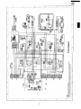
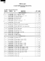
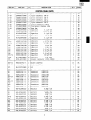
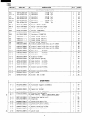
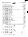
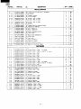
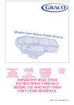
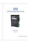
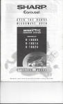
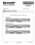
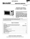
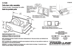
SUPPLEMENTAL
R-l 850A
R-1851A
R-l852A
SERVICE MANUAL
S98M121 R1850A
------
OVER THE RANGE
MICROWAVE OVENS
R-l 850A/R-1851 A/R-l 85249
R-1851A
Model
In the interest of user-safety the oven is to be restored
to its original condition and only the parts identical to
those specified should be used.
This is a supplemental Service Manual for Models R-l 850A/R-1851A/R-1852A.
This model is quite similar to the Base Model R-l 850 (S/M# S6804R185OXDJ
Use this supplemental manual togetherwith the Base Model Service Manualsforcomplete
operation and service information.
TABLE OF CONTENTS
PAGE
SECTION
PRECAUTIONS TO BE OBSERVED BEFORE AND DURING SERVICE TO
AVOID POSSIBLE EXPOSURE TO EXCESSIVE MICROWAVE ENERGY. ...........
Before Servicing .............................................................
Warning ............................................................
Forewordand
Warning to Service Personnel ......................................................
Microwave Measurement Procedure ...........................................................
...................................................................
Wiring/SchematicDiagram
Parts ......................................................................................
....................................................................
PackingandAccessories
SHARP ELECTRONICS
Inside Front Cover
Inside Front Cover
1
2
3
4
6
13
CORPORATION
Service Headquarters: Sharp Plaza, Mahwah, New Jersey, 07430-2135
R-1850A
R-185lA
R-l 852A
(a)
Do not operate or allow the oven to be operated with the door open.
04
Make the following safety checks on all ovens to be serviced before activating the magnetron
or other microwave source, and make repairs as necessary: (1) Interlock operation, (2) proper
door closing, (3) seal and sealing surfaces (arcing, wear, and other damage), (4) damage to
or loosening of hinges and latches, (5) evidence of dropping or abuse.
(d
Before turning on microwave power for any service test or inspection within the microwave generating compartments, check the magnetron, waveguide or transmission line, and cavity for
proper alignment, integrity, and connections.
(4
Any defective or misadjusted components in the interlock, monitor, door seal, and microwave
generation and transmission systems shall be repaired, replaced, or adjusted by procedures
described in this manual before the oven is released to the owner.
03
A microwave leakage check to verify compliance with the Federal
should be performed on each oven prior to release to the owner.
performance
standard
(RD21101U
Before servicing an operative unit, perform a microwave emission check as per the Microwave
Measurement Procedure outlined in the base model service manual. If microwave emissions level
is in excess of the specified limit, contact
SHARP ELECTRONICS CORPORATION
immediately Q l-800-237-4277.
If the unit operates with the door open, service person should 1) tell the user not to operate the oven
and 2) contact SHARP ELECTRONICS CORPORATION and DHHS immediately.
Service personnel should inform SHARP ELECTRONICS
CORPORATION
of any certified unit
found with emissions in excess of 4mW/cm2. The owner of the unit should be instructed not to use
the unit until the oven has been brought into compliance.
I
(RD81001 U)
SERVICE MANUAL
SHARC,
Over The Range
Microwave Ovens
R-l 850A/R-1851 A/R-l 852A
Foreword
This manual has been prepared to provide Sharp
Electronics
Corporation
personnel
with complete
operation and service information for Sharp microwave
oven models R-l 850A/R-1851 AIR-1 852A
It is recommended
that service personnel carefully
study the entire text of this manual so they will be
qualified to render satisfactory customer service.
Check interlock switches and the door seal carefully.
Special attention must be given to avoid electrical shock
and microwave radiation hazards.
This supplemental
service manual contains update information only. Please refer to base model
service manual (R-1850) for complete service information.
WARNING
Never operate the oven until the following
ensured:
points are
(A)The door is tightly closed.
(B)The door brackets and hinges are not defective.
(C)The door packing is not damaged.
(D)The door is not deformed or warped.
(E)There are no other visible signs of damage to the
oven.
DANGER
Certain initial parts are intentionally not grounded
and present a risk of electrical shock only during
servicing. Service personnel - Do not contact the
following parts while the appliance is energized;
High Voltage Capacitor, Power Transformer, Magnetron, High Voltage Rectifier Assembly and High
voltage Harness.
If provided, Vent Hood, Fan Assembly and Cooling
Fan motor.
All of the parts marked “*I’ on parts list are used at voltages more than 250V.
Removal of the outer case cabinet
voltage above 25OV.
gives access to
All of the parts marked “A” on parts list may cause undue microwave exposure, by themselves, or when
they are damaged, loosened or removed.
Sharp Electronics Corporation
Sharp Plaza
Mahwah, New Jersey 07430-2135
I
WARNING TO SERVICE PERSONNEL
Microwave ovens contain circuitry capable of
producing very high voltage and current. Contact with following parts may result in a severe,
possibly fatal, electrical shock.
(EXAMPLE)
High Voltage Capacitor, High Voltage Power
Transformer, Magnetron, High Voltage Rectifier
Assembly, High Voltage Harness etc..
Read the Service Manual carefully and follow all
instructions.
Don’t Touch !
Danger High Voltage
Before Servicing
1, Disconnect the power supply cord and then remove
outer case cabinet.
2. Open the door and block it open.
3. Discharge the high voltage capacitor.
WAl?NING:RISK OF ELECTRICAL
THE HIGH VOLTAGE CAPACITOR
When the testing is completed
1. Disconnect the power supply cord and then remove
outer case cabinet.
2. Open the door and block it open.
3. Discharge the high voltage capacitor.
4. Reconnect the leads to the primary of the power
transformer.
5. Re-install the outer case cabinet.
6. Reconnect the power supply cord after the outer
case cabinet is installed.
7. Start the oven and check all functions.
SHOCK. DISCHARGE
BEFORE SERVICING.
The high-voltage capacitor remains charged about 60 seconds after the oven has been switched off. Wait for 60 seconds and then short-circuit the connection of the high voltage capacitor (that is the connecting lead of the high voltage
rectifier) against the chassis with the use of an insulated
screwdriver.
After repairing
Whenever troubleshooting is performed, the powersupply must be disconnected. In some cases it may be necessary to connect the power supply after the outer case
has been removed, in this event:
1. Reconnect all Lads removed from components during testing.
2. Re-install the outer case (cabinet).
3. Reconnect the power supply cord after the outer
case is installed.
4. Reconnect the power supply cord after the outer
case is installed.
5. Run the oven and check all functions.
Microwave ovens should not be operated empty. To test
for the presence of microwave energy within a cavity,
place a cup of cold water on the oven turntable, close the
door and set the power to HIGH and set the microwave
timer for two (2) minutes. When the two minutes has
elapsed (timer at zero), carefully check to see if the water is hot. If the water remains cold, carry out Before
Servicing procedure and re-examine the connection to
the component being tested.
1. Disconnect the power supply cord and then remove
outer case cabinet.
2. Open the door and block it open.
3. Discharge the high voltage capacitor.
4. Disconnect the leads to the primary of the power
transformer.
5. Ensure that the leads remain isolated from other
components and oven chassis by using insulation
tape.
6. After the above procedure, reconnect the power supply cord.
When all service work is completed and the oven is fully
assembled, the microwave power output should be
checked and the microwave leakage test should be carried out.
2
R-l 85OA
;:;gs
MICROWAVE MEASUREMENT
After adjustment of the door, interlock and monitor
switches are completed individually or collectively, a INTERLOCK SWITCH TEST and MICROWAVE LEAKAGE TEST must be performed to assure compliance
with DHHS (CDRH) Performance Standards for Microwave Ovens.
Interlock Switch Test
Make sure that the door sensing switch, secondary interlock switch and monitor switch are operating properly
by checking with an ohmmeter.
Refer to the “Test Procedure” of the door sensing switch,
secondary interlock switch and monitor switch.
2. Place the oven tray in the oven cavity.
3. Place the load of 275 & 15ml(9.8 oz.) of tap water initially at 20 z!z5OC (68OF) in the center of the oven cavity.
The water container shall be a low form of 600 ml (20
oz.) beaker with an inside diameter of approximately
8.5 cm (3 % in.) and made of an electrically nonconductive material such as glass or plastic.
The placing of this standard load in the oven is important not only to protect the oven, but also to insure that
any leakage is measured accurately.
4. Set the cooking control on Full power cooking mode.
5. Close the door and put the oven into a cook cycle for
several minutes. If the water begins to boil before the
survey is completed, replace it with 275ml of cool water.
Microwave Leakage Test
Requirements
1. Microwave leakage limit (Power density limit).
The power density of microwave radiation emitted by
a microwave oven shall not exceed 1mW/cm* at any
point 5cm or more from the external surface of the
oven, measured prior to acquisition-by the purchaser,
and thereafter (through the useful life of the oven)
5mW/cm* at any point 5cm or more from the external
surface of the oven.
2. Safety interlock switches.
Primary interlock relay and door sensing switch will
prevent microwave radiation emissions in excess of
the requirement
as above mentioned, secondary
interlock switch shall prevent microwave radiation
emission
in excess of 5 mW/cm* at any point 5cm
or more from the external surface of the oven.
Preparation
PROCEDURE
For Testing
Leakage Test
Closed-door
leakage test (microwave
measurement).
1. Grasp the probe of the survey instrument and hold it
perpendicular to the gap between the door and the
body of the oven.
2. Move the probe slowly, not faster than lin./sec
(2.5cm/sec.) along the gap, watching for the maximum indication of the meter.
3. Check for leakage at the door screen, sheet metal
seams and other accessible positions where the continuity of the metal has been breached (eg., around
switches, indicator and vents).
While testing for leakage around the door pull the
door away from the front of the oven as far as is permitted by the closed latch assembly.
1. Make sure that the actual instrument is operating normally as specified in its instruction booklet.
4. Measure carefully at the point of the highest leakage
and make sure that the highest leakage is no greater
than 4 mW/cm* to allow for measurement uncertainty,
and that the secondary interlock switch does turn the
oven OFF before any door movement.
Note: Survey instruments
Note: After servicing,
Before beginning the actual measurement
proceed as follows:
of leakage,
that comply with the requirement for instrumentatoin 21 CFR1030.1 O(c)(3)(i),
as prescribed by the performance standard for
microwave ovens must be used for testing.
and microwave
record data on service
leakage report.
invoice
R-l 850A
R-l85lA
R-1852A
A
BJ
n-m
n-w n
Gz
n-la
LHM
KUMS
C
1
I
Dl
E
tlOLoyy
NOl133ANO3
=-@zG
378VJNWlL
AMO
---I
I
i
F
G
H'
I-
MOLOW
tl3dVWCl
R-l 85OA
R-1851A
R-l 852A
31
)I
1
I
2
3
4
5
5
6
PARTS LIST
Contact your nearest SHARP Parts Distributor to order.
For location of SHARP Parts Distributor, Please call Toll-Free;
1-800-BE-SHARP
“ Q ” MARK - Spare
[
REF NO.
PART NO.
r
*
t
*
*A
section.
parts delivery
DESCRIPTION
/§)
ELECTRICAL
l-
1
FH-DZBOlOMRYO
M
H.V. Rectifier
l- 2
RC-QZBOllMREO
M
H.V. Capacitor
QFS-TA013WREO
M
Oven
l- 4
RHET-A174WREO
M
Convection
l- 5
RMOTDAl82WREO
M
Turntable
l- 6
RMOTDAZlIWREO
M
Stirrer
motor
l- 7
RTHM-0044MRE0
M
Thermal
cut-out
l- 8
RTRN-BO49MREO
Power
l- 9
RV-MZA255WREO
l-10
QFSHDBOO3MREO
M
M
M
1-11
QSW-MAllOWREO
1-12
FFS-BAOl6/KIT
1-13
FACCDBOllMREO
l-14
1-15
QSOCLB006MREO
FH-HZAO53WREO
l-16
QSOCLB006MREO
l-17
FMOTEA362WRKO
1-18
RMOTEA343WREO
l-19
RMOTEA344WREO
l-20
RLMPTA077WREO
1-21
FDTCTA171WRKO
l-22
RMOTDA217WREO
l-23
RR-WZA031WREO
temperature
CODE
PARTS
assembly
l- 3
M
M
M
M
M
-
Q’N
fuse
heater
motor
N.O.
1
1
(15O'C)
60°C
transformer
AM
1
AR
1
AG
1
1
AZ
AQ
1
AQ
2
AG
1
BF
Magnetron
1
BE
Fuse holder
1
AD
Secondary
Monitor
Power
Hood
interlock, Door sensing & damper switches
switch
supply
AE
and fuse assembly
AF
cord
lamp socket
AP
& Oven
lamp socket
AE
Thermistor
AP
M
M
M
M
M
Oven
lamp socket
AE
Hood
fan motor
M
M
M
-
AH
Convection
BM
motor
Ax
Fan motor
Hood
AW
lamp & Oven
lamp
AG
1
1
1
sensor
Damper
Noise
motor
Resistor
CABINET
AW
AP
AK
1
PARTS
2- 1
PFIL-BOO2MREO
E- Grease
2- 2
PDIF-BOllMRFO
2- 2
PDIF-BO12MRFO
M
M
M
M
M
M
M
exhaust louver R-1850A
Hood exhaust louver R-1851A
Hood exhaust louver R-1852A
Base plate left
Outer case cabinet
Outer case cabinet
R-1850A
R-1851A
BE
BE
M
M
Outer case cabinet
R-1852A
BE
AB
AM
AM
2- 2
PDIF-BO13MRFO
2- 3
GDAI-BO52MRPO
2- 4
GDAI-B039MRPO
2- 5
GCABUB065MRPO
GCABUB066MRPO
2- 5
2- 5
2- 6
2- 7
2- 7
2- 7
2-7-l
2-7-l
2-7-l
2-7-2
2- 8
2- 9
2-10
GCABUB079MRPO
TMAPCBO56MRRO
FANGKBOO9MRYO
FANGKBOIOMRYO
FANGKBOllMRYO
LANGQB016MRPO
LANGQBOZOMRPO
LANGQBO27MRPO
PGLSPBOO4MREO
PCOVPB051MRPO
HDECQBOl6MRFO
LSTY-BOlOMRPO
M
M
M
M
M
M
M
M
M
M
-
filter
AF
Hood
Base plate
Schematic
Hood lamp
Hood lamp
Hood lamp
Hood lamp
Hood lamp
1
right
diagram
glass assembly R-1850A
glass assembly R-1851A
glass assembly R-1852A
glass angle R-l850A
glass angle R-1851A
AV
AV
AV
1
AL
1
AH
Sash left
AM
AG
AG
AG
AG
AY
AL
Rear
AG
Hood
lamp glass
Hood
lamp glass
Base
cover
angle
stay
6
R-1852A
REF NO.
PART NO.
I§
DESCRIPTION
(
CONTROL
Q’TY
CODE
1
1
1
1
1
BQ
AC
AC
AC
AC
1
1
1
1
AD
AE
AV
AB
PANEL PARTS
3-l
3-1A
3-1B
3-1c
3-1D
DPWBFB061MRUO
QCNCMA227DREO
QCNCMA23ODREO
QCNCMA234DREO
QCNCMA267DREO
M
J
J
J
J
Control unit
3-pin connector
4-pin connector
5-pin connector
6-pin connector
3-1E
3-1F
3-1G
3-1H
QCNCMA237DREO
QCNCWA030DREO
RV-KXBOO3MREO
PTPEHBOlOMREO
J
J
M
M
3-pin connector
(CN-F)
12-pin connector
(CN-G)
Fluorescent
display tube
Tape 2mm
(CN-A)
(CN-B)
(CN-C)
(CN-E)
Cl
RC-KZAO87DREO
J
Capacitor
0.1 PF 5OV
1
AB
c2
VCEAB31VW108M
J
Capacitor
1000 PF 35V
1
AF
c3
RC-KZA087DREO
J
Capacitor
0.1 PF 50V
1
AB
c4
VCEAB31W106M
J
Capacitor
10 PF 35V
1
AB
c5
RC-KZA087DREO
J
Capacitor
0.1 PF 50V
1
AB
C6
VCEAB31W106M
J
Capacitor
10 PF 35V
1
AB
:7-8
VCKYDllCY103N
J
Capacitor
0.01 PF 16V
2
AH
:9-10
RC-KZA087DREO
J
Capacitor
0.1 PF 50V
2
AB
C20
VCEAB31W106M
J
Capacitor
10 PF 35V
1
AB
"21
VCEAB31HW104M
J
Capacitor
O.lpF 5OV
1
AM
230
VCKYDllCY103N
J
Capacitor
0.01 FF 16V
1
AH
350
VCKYDllCY103N
J
Capacitor
0.01 PF 16V
1
AH
160
VCKYDllCY103N
J
Capacitor
0.01 PF 16V
1
AH
"70-74
VCKYDllHB331K
J
Capacitor
330 OF 50V
5
AA
2100
RC-QZBOl4MREO
M
Capacitor
7 PF 230V
1
AM
:Fl
RCRS-AOlODREO
J
Ceramic
31-4
VHDllESl///-1
J
Diode
(llES1)
320-32
VHDlSS27OA/-1
J
Diode
(lSS270A)
13
AA
(lSS270A)
7
AA
AW
resonator
(CSTI.OOMGW)
1
AD
4
AB
370-76
VHDlSS27OA/-1
J
Diode
[Cl
RH-IZA719DREO
J
LSI
1
1c2
RH-IZA495DREO
J
IC
1
AL
AA
21
VS2sB1238//-3
J
Transitor
(2SB1238)
1
23
VSKRAlOlM//-3
J
Transitor
(KRAlOlM)
1
AB
14
VSDTAl23ES/-3
J
Transistor
(DTAl23ES)
1
AA
220-26
VSKRClOlM//-3
J
Transistor
(KRClOlM)
1
AB
227
VSKRC243M//-3
J
Transistor
(KRC243M)
1
AB
128-30
VSKRAlOlM//-3
VSKRAlOlM//-3
J
Transistor
(KRAlOlM)
1
AB
240
J
Transistor
(KRAlOlM)
1
AB
260
VSKRAlOlM//-3
J
Transistor
(KRAlOlM)
1
AB
190
VSKRAlOlM//-3
J
Transistor
(KRAlOlM)
1
AB
il
VRD-B12HF432J
J
Resistor
4.3m
l/zw
1
AH
?2
VRS-B12EF152J
J
Resistor
1.5m
1/4w
1
AA
13
VRD-B13AA681J
J
Resistor
680521.OW
1
AA
51oa
l/zw
1
AB
1/4w
2
AA
1/4w
1
AA
1/4w
1
AA
<4
VRD-BlZHF511J
J
Resistor
17-8
VRD-Bl2EF472J
J
Resistor
<30
VRD-B12EF153J
J
Resistor
131
VRD-B12EF472J
J
Resistor
4.7m
4.7m
15kR
140
VRD-Bl2EF332J
J
Resistor
3.3m
1/4w
1
AA
150
VRS-B12EF153J
J
Resistor
15m
1/4w
1
AA
4.7m
151
VRD-Bl2EF472J
J
Resistor
1/4w
1
AA
162
VRN-B12EK363F
J
Resistor
36w2
1/4W
1
AA
163
VRN-B12EK221F
J
Resistor
22oa
1/4w
1
AB
7
REF NO.
PART NO.
DESCRIPTION
)§I
CONTROL
R64
VRN-BlZEK362F
J
R70-74
VRD-B12EF332J
R75
VRD-BlZEFlO4J
R76-82
Q’TY
CODE
1
PANEL PARTS
Resistor
3.61dl 1/4W
1
AA
J
Resistor
3.31d2 1/4w
5
AA
J
Resistor
1ooldz 1/4w
1
AA
VRD-B12EF332J
J
Resistor
3.3kf2 1/4w
7
AA
R90-93
VRD-B12EF104J
1ookR
1/4w
4
AA
VRS-B13AA331J
J
J
Resistor
RlOO
Resistor
1w
1
AA
RYl-3
RRLY-A113WREO
M
Relay
3300
(DU241-lP(M))
3
AH
RY4-9
RRLY-A080DREO
J
Relay
(OJE-SS-124LM)
6
AG
RYlO
RRLY-112MREO
M
Relay
(VE-24HS5-K)
1
AM
SP40
RALM-A014DREO
J
Buzzer
(PKM22EPT)
1
AG
I?1
RTRNPB004MREO
M
Transformer
1
AN
VRSl
RH-VZA032DREO
J
Varistor
1
AE
ZDl
VHEHZ6A3///-1
J
Zener
diode
(HZ6A-3)
1
AC
ZD2
VHEHZ161///-1
J
Zener
diode
(HZ16-1)
1
AA
ZD3
VHEHZ5CZ///-1
Zener
diode
(HZ5C-2)
1
AA
ZD4
VHEHZ4A2///-1
J
J
Zener
diode
(HZ4A-2)
1
AA
3-2
FPNLCB153MRKO
M
Control
panel
with
key unit R-1850A
1
BB
3-2
FPNLCB154MRKO
M
Control
panel
with
key unit R-1851A
1
BB
3-2
FPNLCB170MRKO
M
Control
panel
with
key unit R-1852A
1
BB
3-2-l
FUNTKB108MREO
Key unit
R-1850A
1
AX
3-2-l
FUNTKB109MREO
M
M
Key unit
R-1851A
1
AX
3-2-l
FUNTKBl25MREO
M
Key unit
R-1852A
1
AX
3-2-2
GMADIBO23MRFO
M
Display
1
AD
3-2-3
MSPRTA050WREO
M
3pen button
1
AA
3-2-4
JBTN-B053MRFO
M
Dpen button
R-1850A
1
AD
3-2-4
JBTN-B054MRFO
M
3pen button
R-1851A
1
AD
3-2-4
JBTN-B066MRFO
M
3pen button
R-1852A
1
AD
3-2-5
JBTN-B067MRFO
M
Select
buttonR-1850A
1
AC
3-2-5
JBTN-B056MRFO
M
Select buttonR-1851A
1
AC
3-2-5
JBTN-B055MRFO
M
Select buttonR-1852A
1
AC
3-2-6
LAIiGQBO36MRPO
M
Key fixing
1
AA
3-3
XEPSD30PlOXSO
M
-
Screw;
5
AA
1
AM
r
(104G471K)
window
spring
3mmxlOmm
1
OVEN PARTS
4-
1
4-
2
FROLPB020MRKO
M
Turntable
support
1
AS
4-
3
NTNT-B006MREO
M
Turntable
tray
1
AZ
4-
4
LANGKBOlOMRPO
M
Capacitor
holder
1
BB
4-
5
FCOVPB002MRYO
Stirrer
cover
1
AM
FFAN-B003MRKO
-__--__----_--
M
M
Stirrer
fan assembly
1
M
Oven
AL
--
FFTA-B003MRKO
M
Exhaust
damper
assembly
assembly
4-
6
4-
7
4-
a
DHET-BOOlMRKO
M
Convection
4-
9
NCPL-B007MRFO
M
Coupling
4-10
NFANMB003MRPO
M
Convection
Motor
4-11
LANGQB031MRPO
M
Convection
Motor
cavity
4-12
PPACGB013MREO
M
Turntable
4-13
LBNDK0054WREO
M
Heater
4-14
NFANMB004MRPO
M
Convection
4-15
PHOK-B013MRFO
M
-
Latch
assembly
(Not a renlaceble
motor
motor
1
1
BL
1
AE
fan
1
AE
angle
1
AF
heater
mounting
nart)
unit
packing
1
AC
holder
2
AD
fan
hook
8
1
AE
1
AG
REF NO.
PART NO.
DESCRIPTION
I§1
OVEN
- -.
4-16
Q’TY
CODE
PARTS
~~
4-17
4-18
FANGTBOO3MRYO
PFPF-B002MREO
PPIPFB002MREO
M
M
M
Unit mounting angle
Heat protect L
Caller
1
2
1
4-19
4-20
4-21
4-22
PREFHBOO6MRPO
PDUC-BO83MRPO
NFANPBOO5MREO
GBDYRB002MRPO
M
M
M
M
Heater Cover L
Hood intake duct
Fan blade
Back plate
4-23
4-24
4-25
4-26
4-27
4-28
4-29
FDUC-BO25MRKO
LBSHCOO37WREO
FDUC-BO22MRKO
MLEVPBOl6MRFO
PCUSGB03OMRPO
MCAMPBOOlMRFO
PCUSUBO32MRPO
M
M
M
M
M
M
M
Fan duct
Cord bushing
Exhaust duct
Open lever
cushion
Damper cam
Damper cushion
4-30
4-31
PFPF-BOOlMREO
PFTA-BOO3MRPO
M
M
Heat protect
Damper plate
1
1
1
1
1
1
1
1
1
1
1
1
AV
AK
AD
AM
AG
AD
AX
AM
AB
AK
AD
AC
AC
AC
AD
4-32
4-33
4-34
4-35
PREFHBOO4MRPO
LANGQB033MRPO
PREFHBOOSMRPO
LSTPPBO24MRFO
M
M
M
M
Thermal cover R
Hood lamp angle
Thermal cover bottom
Door stopper
1
1
1
1
1
AD
AK
AM
AK
AD
4-36
4-37
4-38
PCOVPB047MRPO
PCOVPBOSOMRPO
PCUSGB027MRPO
M
M
M
Oven lamp cover
Heat protect top sheat
cushion
4-39
4-40
M
M
Hood exhaust
Top duct
4-41
PDUC-B056MRFO
PDUC-BO57MRFO
PDUC-B058MRFO
M
Magnetron
4-42
4-43
4-44
4-45
PDUC-B060MRPO
PFILWA035WREO
PFPF-B003MREO
PCUSUB018MRPO
M
M
M
M
Hood intake duct R
Oven light screen
Heat protect top
Exhaust cushion A
4-46
4-47
4-48
4-49
4-50
PCUSUB019MRPO
PCUSUB02OMRPO
PCUSUB024MRPO
PCUSUB033MRPO
PCUSGBO35MRPO
M
M
M
M
M
Exhaust
cushion
cushion
cushion
cushion
4-51
4-52
PCUSUBO47MRPO
PCUSUB046MRPO
M
M
5- 0
5- 0
CDORFB166MRKO
M
CDORFB167MRKO
M
L
R
1
AD
1
1
1
1
AK
AA
AY
AN
1
1
1
1
1
AD
AH
AF
AE
AA
1
1
1
1
2
AA
AA
AA
AA
AA
cushion
cushion
1
2
AA
AA
DOOR PARTS
Door assemblyR-1850A
Door assemblyR-185lA
1
BL
1
BN
1
BN
duct
duct
cushion
B
5- 0
CDORFB19OMRKO
M
Door
5- 1
FDORFBO53MRTO
M
Door panel
5- 2
GWAKPBO58MRFO
M
Door
frame
R-1850A
frame
R-1851A
assemblyR-1852A
1
BB
1
AX
5- 2
GWAKPBO76MRFO
M
Door
5- 2
5- 3
GWAKPBO58MRFO
PGLSPB008MRRO
M
M
Door frame
Door glass
R-1852A
front
R-1850A
5- 3
1
PGLSPBOlOMRRO
BD
M
Door glass
front
R-1851A
1
BD
front
R-1852A
5- 3
PGLSPBOllMRRO
M
Door
5- 4
GCOVHB031MRFO
M
Choke
cover
LSTPPB025MRFO
LSTPPB028MRFO
M
Latch
5- 6
M
Glass
5- 7
MSPRTA046WREO
M
Latch
XCTSD40P08000
M
Screw
5- 5
5- 8
glass
1
AX
1
AX
1
BD
1
AM
head
1
AE
stopper
1
AD
spring
1
AB
6
AA
9
REF NO.
PART NO.
DESCRIPTION
101
Q’TY
CODE
1
1
4
1
2
AM
AC
AC
AC
AC
1
CFZK-B131MRKO
LBSHCOO4OMREO
LX-BZ0195WREO
LX-MZBOOlMREO
XBRSD50P60000
Installation material
Gromment
Toggle screw
Cord holder
Screw; 5mm x 6Omm
6-l-5
XOTSD40P12000
M
Screw;
4mm x 12mm
1
AA
6-l-6
6-l-7
6- 2
XTSSD50P35000
XWHSDSO-16300
TINSEB141MRRO
TINSEB199MRRO
M
M
M
M
Screw; 5mmx
35mnl
Washer
Installation
instructions
Operation manual
6
2
1
1
AA
AA
AD
AE
TINSKB018MRRO
TINSKB019MRRO
QW-QZBOllMREO
TCADCB012MRRO
FW-VZB166MREO
M
M
M
M
M
Top
Wall
High
Cook
Main
1
1
1
1
1
AD
AD
AD
AP
AY
High rack
Low rack
Main harness C
Caution label
DHHS caution label
1
1
1
1
1
AQ
AP
AH
AA
AB
Monitor
1
AA
UAMI-B007MRMO
UAMI-B008MRMO
FW-VZB077MREO
TCAUAAO25WRRO
TCAUAB005MRRO
(
assembly
6-14
TCAUABO15MRRO
777777-
1
2
2
3
4
5
xCPSD40P08000
XOTSF40PlOOOO
XOTSE40PlOOOO
XCBSD30P08000
XBTSD40P08RVO
XCBSD30P08000
7- 6
7- 7
7- 8
7- 8
7- 9
7-10
XBTWW40P06000
XOTSD40P12000
XOTSF40P12000
XOTSE40P12000
LX-BZO208WREO
LX-BZBOllMREO
7-11
7-12
7-13
7-14
7-15
1M
w
template
template
voltage wire A
book
wire harness A
caution
label
FASTENERS
x
x
x
x
x
x
8mm
1Omm
R-1850A
1Omm R-1851A, R-1852A
8mm
6mm
8mm
2
3
3
2
2
2
AC
AC
AA
AA
AA
M
M
M
M
M
M
Screw; 4mm x
Screw; 4mm x
Screw; 4mm x
Screw; 4mm x
Screw; 4mm x
Unit mounting
8mm
12mm
1Omm
R-1850A
1Omm R-1851A, R-1852A
8mm
screw
2
26
3
3
2
2
AA
AA
AA
AA
AA
AH
LX-CZA038WREO
xcBWW30P08000
LX-CZOO52WREO
XCTWW4OPO8RVO
XRESD40-06000
M
M
M
M
M
Special screw
Screw; 3mm x 6mm
Special screw
Screw; 41~n x 8mm
E-ring
4
8
2
2
1
AA
AA
AA
AC
AA
7-16
7-17
7-18
7-19
7-20
XOTSD40P12000
XCTWW40P08000
XOTWW4OP10000
xwsUW40-10000
LX-BZ0081YBEO
M
M
M
M
M
Screw;
Screw;
Screw;
Spring
Screw;
2
3
8
1
9
AC
AA
AA
AA
AA
7-21
7-22
7-23
7-24
XWHSD50-20120
XWHUWIO-08100
XWHUWIO-08120
XOTSD40P08000
M
M
M
-M
Washer; 5mmx
2INn
Washer; 4mm x 0.8mn
Washer; 511m x 0.8mm
Screw; 4mm x 8mm
1
2
1
8
AA
AA
AA
AA
M
M
M
M
M
Screw;
Screw;
Screw;
Screw;
Screw;
Screw;
4mm
4mm
4mm
3mm
3mm
3mm
4mm x
4mm x
4m-1 x
Washer
4mm x
12mm
8mm
8mm
8mm
10
AA
A
IA
B
IC
C
t
ID
D
c
E
E
F
IF
3
L
1
E
G
It
Ii
I
1
2
4
3
11
5
6
R-l 850A
Fb1851A
R-l 852A
1
I
3
I
3
4
5
6
Control Panel Assembly
B
C
L
,
IE
‘1
/
I
I
I
I
I
I
I
I
I
I
I
\
I
I
I
I
I
I
I
I
I
I
F
L
/
/
/
/
/
lc
t
1
2
__-l
3
4
12
5
6
r
1
I
I
2
3
I
4
5
6
Miscellaneous
A
I’
I
I
I
_I
I
I
I
I
B
l
I
I l
I
---------_________
--I
C
-1
Packing and Accessories
D
OPERATION MANUAL
E
F
\.
PACKING CASE
_
G
0 Non-replaceable items
SHARF?
‘980 SHARP CORP. (9M2.70E)
Printed in U.S.A.