1
R-m5i-j
R-SH52
SHARP
SERVICE MANUAL
Sll 01 R9A52J//
CONVECTION
MICROWAVE
MODELS
OVEN
R-9A52
R-9H52
In interests of user-safety the oven should be restored to its original
condition and only manufacturer original spare parts must be used.
This is a supplemental
Service Manual for Model R-9A52 etc.
Those models are quite similar to Base Model R-9HlO (Refer No. is S9808R9Hl OJ//).
Use this supplemental
manual together with the Base Model Service Manual.
Refer to the Base Model Service Manual for complete operation, service information, etc.
TABLE
OF CONTENTS
Page
1
FOREWORD . ...... ... ... . ... ... . ... ...... .. ........ ..... .... ............ ..... ....*................................................................................
1
.. ... .......... ......... ....*............................................*...*...............*............
CAUTION, MICROWAVE
RADIATION
PRODUCT DESCRIPTION
*..*.......*.......................................................*.............,.......,.....................................
;
OPERATING INSTRUCTIONS
.. ....*...................*.................*....*..................................................,.....,..............
. ....... .... ...... .... ... ..... .. ... .......... ...... .... ............. ... ... ... ... ... .... ......... ... ... ....... ............................. 5
WIRING DIAGRAM
PROCEDURE ... ..... .......... .... ..... .......... ... ... .... ......... 7
AND ADJUSTMENT
REPLACEMENT
COMPONENT
. .. ........ ... ....... ........... ........... ............. ... ... ... ...... .. ...... .. ......... ...... ........ .. ....... .................... 9
PICTORIAL DIAGRAM
IO
.. ....*......................*..........................................................................
CONTROL PANEL ClRCUIT(R-9A52)
11
CONTROL PANEL CIRCUIT(R-9H52)
...... .. ...... .. ............~..........................................................................
12
PARTS LIST ....... .... ... ....... .... ...... .... ... ..... ..... .... ... ... .... ..... ........... ... ......... ....... ... ......... ...... ... ..............................
PACKING AND ACCESSORIES
. ... ....*................................~....................................................................*...*
18
SHARP CORPORATION
1
’ R-9A52
R-9H52
R-SA52
R-SH52
4
1
SERVICE MANUAL
SHARP
COUNTER
CONVECTION
GENERAL
TOP
MICROWAVE
R-9A52/
$4 .g.j&C
I .‘J
i&g
%I
2:-g OPERATING
OVEN
1
;$L);
;
. - ” ._M..” .
$4. .an?nPI
R-9H52
IMPORTANT
.I-
sx”z-PRODUCT DESCRIPTION
_^”
INSTRUCTIONS
>,
^. . ___-
??’ WIRING DIAGRAM
‘ *
“$<T
INFORMATION
This Manual has been prepared to provide Sharp Corp. Service
engineers with Operation and Service Information.
*c ,
,” ^1‘., t;9%
-%arl’sv”,:2m3b?,z
- --~~
‘:Ez COMPONENT REPLACEMENT
f-it?
PROCEDURE
_I
.. AND ADJUSTMENT
It is recommended
that service engineers carefully study the
entire text of this manual and Base Model manual, so they will
be qualified to render satisfactory customer service.
ti;, WIRING
xI
CAUTION
MICROWAVE
RADIATION
ge
I?
i “r,$O,FI
,:p*-;*, :3
IB2,
J‘6-r
Service engineers should not be exposed to the microwave energy which may radiate from the magnetron or
other microwave generating devices if it is improperly
used or connected.
All input and output microwave
connections,
waveguides,
flanges and gaskets must be
secured. Never operate the device without a microwave
energy absorbing
load attached.
Never look into an
open waveguide
or antenna while the device is energized.
‘: PARTS LIST
?r;
WARNING
Never operate the oven until the following
points are
ensured.
(A)The door is tightly closed.
(B)The door brackets and hinges are not defective.
(C)The door packing is not damaged.
(D)The door is not deformed or warped.
(E) There is not any other visible damage with the oven.
Servicing and repair work
trained service engineers.
must be carried
out only
QTun
(
I. . _*:
^ ‘-$A w
.w *
*
y$“z,~
‘_’I
i
^.
‘
:p -J&q&
3 E-‘L s-9.“‘
7*x8*“*“jJ
,+$-&?-;:
-=.a
.“q”
,‘-“A
by
t
All the parts marked ‘I*” on parts list are used at voltages
more than 250V.
‘y
:;/3+,-+!
;
_-.-
+ *t-j
-
I
f
f
; ‘$%”
~Uj~~~Q‘..sA
^.
.
.
---.
j
Cllrs.XI.
tj
-_-.-
1;
i Ie:;*QJ
s *- rie%w.~..mm.w”.n-r~-*~~~~~
’
SHARP
CORPORATION
OSAKA,
JAPAN
1
k-9A52
R-9H52
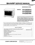
PRODUCT
DESCRIPTION
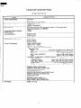
SPECIFICATIONS
DESCRIPTION
ITEM
Power Requirements
240 Volts
50 Hertz
Single phase, 3 wire earthed
Power Consumption
1500W
1600W
Power Output
750 watts nominal of RF microwave
Operating frequency of 2450M Hz
-Convection
Heating
Power Output
element
Control
Cavity
energy
1500w
Dimensions
Complement
Width 41 Omm
Height 245mm
Depth 41 Omm
Touch Control System
Clock( 1 :OO - 12:59 )
Timer (0 - 99 min. 99sec. )
Microwave
Power for Variable Cooking
Repetition Rate;
. .... ... ..... ...*.........*....*. Full power throughout
the cooking time
HIGH
MED HIGH
..,,.,..*..,,....................I.*....*...... approx. 70% of Full Power
MED
... ....... .. ... ...... ...... ....... ... ... .. .. .. .... ... ... .. approx. 50% of Full Power
.. ... ... ... . .. . ... ... ... .. approx. 30% of Full Power
MED LOW (DEFROST)
... ....... .... .. ...... ..... ....... ... ... ....*............. approx. 10% of Full Power
LOW
Convection Temperature for Variable Cooking
CONVECTION
. ... ..... ....... ... ....*...........*.. 40 to 250°C Temp. control
LOW MIX, BAKE
... .. ....... .. .... .. 180°C with 10% microwave power
HIGH MIX, ROAST
... ..... ... ... .. 200°C with 30% microwave power
. ... .... ... .......... ... .. .... .. 130°C for 4 hours (no preheat)
SLOW COOK
. ... ..... .... ... .... ... ... ............. .... ...... ...... ... ... ... ...... 250°C (preheat)
GRILL
Variable cooking control pads,
SENSOR COOK pad (R-9H52 only),
AUTO START/CLOCK
pad,
EASY DEFROST pad,
ONE TOUCH REHEAT pad (R-9H52 only),
COMPU COOK pad (R-9H52 only),
STOP/CLEAR
pad,
-<
MEMORY pad,
INSTANT COOK/START
pad,
AUTO COOK pad (R-9A52 only),
EASY REHEAT pad (R-9A52 only)
t
Set Weight
(2 litre water load)
Width 627mm
Height 378mm
Depth 481 mm
C:,se Dimensions
Cooking
( Microwave)
(Convection)
Approx.
30.0 kg
R-9A52
I?-9H52
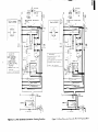
OPERATING
1
I
INSTRUCTIONS
I
I
*Place
the
roller
coupling
the turntable
1. Ventilation
2. Access
openings
cover
for
6. Oven
oven
8. Door
replacement
9. Touch
3. Hinges
Touch
10. Lighted
latches
door
4. Safety
5. See through
12. Roller
open
digital
Control
Panel
to select
14. Low
rack
display
15. High
rack
-
sensor
Compu
cook
-NUMBER
PADS
L
-MEMORY
Cook
VARIABLE
_
CONVECTION COOKING
FUNCTION PADS
Touch
to set
start time.
1
_
funct
AUTO START/CLOCK
clock
AND TEMPERATURE
PAD
PAD----,
.
Touch
to
erase
during
programming.
Touch once to stop operation
of oven during cooking;
touch
twice
to
cancel
cooking
programme.
COOKING
CON-
Touch
to select
microwave
power setting.
If not touched,
HIGH is automatically
selec-
HIGH MIX
ROAST
I
8
220%
LOW MIX
BAKE
I
9
230-C
MORE( A
CONVECTION
1
or auto
STOP/CLEAR PAD
.
re-
Touch to enter one frequently used cooking
programme.
Touch to recall the memorized
programme.
by en-
for each
automatic
Touch to enter cooking times,
clock time, convection
temperature
or to select
the
Sensor
or
Compu
Cook
categories.
EASY DEFROST PAD
Touch to defrost
meat
tering weight
only
TOUCH REHEAT PAD
Touch to start
heat cycle
SENSOR COOK
COMPU COOK MENUS
to cook
cover
Stay
Panel
COMPU COOK PAD
Touch
tion.
stay.
W9H52)
SENSOR COOK MENUS i
to select
and seat
roller
door
SENSOR COOK PAD
Touch
mode
on the
13. Turntable
button
Control
-ONE
Touch
mode
on the
11. Waveguide
lamps
7. Coupling
lamp
stay
in the oven
-INSTANT
1
1, LESS( v)
PADS.
Touch
to increase/decrease
the time in one minute
increments during cooking or to increase/decrease
the
time
whilst
programming
the One
Touch Reheat,
Sensor Cook,
Compu Cook or Easy Defrost
modes.
COOK/START
PAD
Touch
once
to cook
for
1
minute at HIGH or increase by
1 minute multiples
each time
this pad is touched
during
microwave,
convection,
grill
or mix cooking.
3
R-9A52
R-9H52
Touch
Control
Panel
lR-gA52)
MULTI COOK
MULTI COOK PAD
Touch
mode
to
select
Multi
Cook
r
MULTI COOK MENUS
I
AUTO START
CLOCK
-AUTO
1 Roast beef
2 Roast iamb
3 Roast chicken
4 Roast dmner
5 Mlxed grill
6 Cake layers
7 Jacket
potatoes
-NUMBER
PADS
Touch
mode.
to select
Easy
EASY REHEAT
4
150°C
Reheat
1 Dinner
4
5
EASY DEFROST PAD
Pies
6
Beverage
CON-
Touch
to select
microwave
power setting.
If not touched,
HIGH is automatically
selected.
to defrost
weight
only.
Touch to enter one frequently used cooking
programme.
Touch to recall the memorized
programme.
MORE( A
CONVECTION COOKING
FUNCTION PADS
to cook
auto
AND TEMPERATURE
-VARIABLE
COOKING
TROL PADS
180°C
MEMORY PAD
Touch
tion.
PAD
or
plate
2 Chlcken
pieces
3 Casserole / Soup
EASY REHEAT MENUS
Touch
tering
I
clock
Touch to enter cooking times,
clock time, convection
temperature or to select the Multi
Cook or Easy Reheat menus.
--I
EASY REHEAT PAD
START/CLOCK
Touch
to set
start time.
-
CONVECTION
0
250°C
for each funcGRILL
I
1, LESS( ~1
PADS
Touch
to increase/decrease
the time in one minute increments during cooking or to increase/decrease
the
time
whilst programming
the Easy
Reheat,
Multi Cook or Easy
Defrost
modes.
SLOW COOK
~
STOP/CLEAR PAD
Touch
to erase during
programming.
Touch once to stop operation
of oven during cooking; touch
twice
to
cancel
cooking
programme.
L
STOP
CLEAR
INSTANT COOK
START
4
_
-INSTANT
COOK/START
PAD
Touch
once to cook
for 1
minute at HIGH or increase by
1 minute multiples
each time
this pad is touched
during
microwave,
convection,
grill
or mix cooking.
A4
d-4
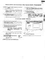
240V--5OHz
240V--5OHz
OVEN
Note: For R-9H52
OVEN
THERM0
MONITOR
CUT-OU
0.8/2OW
,____.__________._.
150’
RESISTOR
MONITOR
SWITCH
TEMP.
\
FUSE
150%
THERM0
Note: For R-9H52
CUT-OUT
c
,--_-._-___-._____.
150-c
0.8/2OW
1
Note
._______...---___-______
,
FM
OL
;
f-B-+
OL
.d
OL
lHERl.40
CUT90’
OL
i
* ---.._
OVEN
Lz_-
LAMP
:
___________
I
/
FM
THERMO
OUT
CUT-
c
90’
----_
i
OL
+-p
i
--------------____J
UPPER
UPPER
LATCH
‘I
SW1 TCH
G-
LOWER
LATCH
LATCH
SWITCH
SWITCH
SENSOR
COOKING
LOWER
LATCH
(R-9H52
SW1 TCH
’ E-31
4,
::::,R
SCHEMATIC
@$
E-4
NOTE: CONDITION
NOTE: CONDITION
OF OVEN
1. DOOR CLOSED
2. “SENSOR COOK”
PAD TOUCHED
3. “START” PAD
TOUCHED
E-5
1. DOOR CLOSED
2. CLOCK
APPEARS
CONTROL
UN 1 T
m
F-
I
F-2
A
s
Ii
E-5
DAMPER
I
SW1 TCH
CONTROL
I
UN I T
--F-3
TAB
I
HIGH COOKING
I
I
t
-7
CM
6-Y
STM
CONVECTION
OF OVEN
1. DOOR CLOSED
2. COOKING TIME
PROGRAMMED
3. VARIABLE COOKING
CONTROL “HIGH”
4. START PAD TOUCHED
MOTOR
TURNTABLE
MOTOR
_
POWER
’
TRANSFORMER
ASYMMETRIC
RECTIFIER
H.V.
RECTIFIER
%
-II--I===
-L---
MAGNETRON
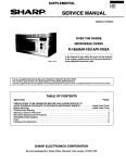
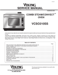
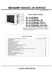
Figure
O-l.
OUT
c
Oven
Schematic-OFF
Condition
7
H.V.
RECTIFIER
MAQNETRON
3-J
Figure
O-2.
Oven
Schematic-High
and
Sensor
Cooking
Condition
A-4
240V-50Hz
MONITOR
MONITOR
RESISTOR
OVEN
SWITCH
MONITOR
o.a/2ow
Note: For R-9H52
-1
RESISTOR
MONITOR
‘I””
Q
o.a/2ow
fi%;;:
tdnte
SWITCH
._..
(_____---____..-__.--.--~
FM
lHERM0
,__.______-________
I
I
OL
CUT-CJU?
90’
LAMP
:
F-M
-d,l
;
c
OL
i
--------------____,
UPPER
LOWER
LOWER
LATCH
LATCH
LATCH
SWITCH
SWITCH
SWITCH
SCHEMATIC
SCHEMATIC
NOTE:CONDITION
OF OVEN
1 .DOOR CLOSED
2.MIX COOKING PAD TOUCHED
3.DESIRED TEMP. TOUCHED
E-5
NOTE. CONDITION
OF OVEN
1. DOOR CLOSED
2. CONVECTION
PAD
TOUCHED
3. DESIRED TEMP. PAD
TOUCHED
4 START PAD TOUCHED
DAMPER
CONTROL
UN I T
4.START
DAMPER
DAMPER
SWITCH
’
CONTROL
UN I T
i:
PAD TOUCHED
MOTOR
CONVECT:ON
MOTOR
TURNTABLE
CONVECTION
rHERM0
c:u1-OUT
I ?O’c
_----
#
SWITCH
f
OVEN
I
MOTOR
HEATER
--
H.V.
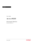
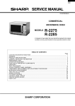
Figure
O-3.
Oven
RECTIFIER
Schematic-Convection
MAGNETRON
Cooking
H.V.
RECTIFIER
MAGNETRON
3-J
Condition
Figure
O-4
Oven
Schematic-Automatic
Mix
Cooking
,
Condition
R-9A52
R-9H52
COMPONENT
REPLACEMENT
WARNING:
AND
To avoid possible exposure to microwave
energy;
A. Before operating the oven
I. Make sure that, when unlatching
the door
slowly, an accompanying
“click” indicating the
actuation
of the monitor
switch
and latch
switches is heard.
2. Check visually
the door seal for arcing and
damage.
B. Do not operate the oven before any of the following conditions are repaired;
1. Door does not close firmly against the front of
appliance.
2. There are a broken door hinge or-support.
OUTER
CASE
ADJUSTMENT
PROCEDURE
3.
4.
The door is bent or warped.
There is any defective parts in the interlock,
oven door or microwave generating and transmission assembly.
5. There is any other visible damage to the oven.
C. Do not operate the oven
1. Without the RF gasket.
2. If the door is not closed.
CAUTION:
DISCONNECT
OVEN FROM
POWER
SUPPLY
BEFORE
REMOVING
OUTER
CASE.
DISCHARGE
HIGH
VO LTAG E
CAPACITOR
BEFORE
TOUCHING
ANY
OVEN
COMPONENTS OR WIRING.
CABINET
REMOVAL
To remove the outer case and proceed as follows;
1. Disconnect oven from power supply.
2. Remove eight (8) screws from the rear and along
the side edge of the case.
3. Remove the two (2) screws (LHSTIX LR-4) from
the lower portion of the oven cabinet back side.
4. Slide the entire case back about 3 cm to free it from
retaining clip on the cavity face plate.
5. Lift the entire case from the unit.
CAUTION:
DISCHARGE
THE
HIGH
VOLTAGE
CAPACITOR
BEFORE
TOUCHING
ANY
OVEN
COMPONENTS
OR
WIRING.
Note:
The outer case cabinet is secured by special
(LH) screw. When securing or loosening the
LHSTIX
(LR-4)
type screw
driver
screw,
should be used.
LH-SCREW(XOTSD40R12RVO)
Removal
LHSTIX
(SIZE
LHSTIX
SCREW
LkTlX
DRIVER
LR-4)
screw
driver
and LHSTIX
screw
SCREW
of LHSTIX
screw
at oven
back side
‘R-9A52
R-9H52
OVEN
1
LAMP
SOCKET
REMOVAL
1. Pull the wire leads from the oven lamp socket by
pushing the terminal hole of the oven lamp socket
with the flat type small screw driver.
plate
2. Lift up the tab of the oven lamp mounting
holding the oven lamp socket.
3. Slide the oven lamp socket left-ward.
4. Now, the oven lamp socket is free.
CAUTION:
When replacing the oven lamp socket, replace it so that the side where the black
dot is put faces left-ward.
Own
Oven
8
lamp sodot
lamp socket
R -9A52
R-9H52
1
A
nl
:
pi:
z
LL
El-
#SY
&
z*
$22
2?4
FjYY
-:2
P
r25
2ola$
F 2;::
$;;
&
Izg2
Wluzz:z
r
P
--
1,
31+
t-2
SE
a=
9g
5
0
Y
0 @
46
0’ 00
ss
r
r
c
s
s
I;”
.7ij
.k
w
0
.P.
r
c;>
2
z .-s
i IA
-2
n
d-“I
a’
a
H
1
I
2
3
4
9
5
6
R
1;
15’13ebb
ID
ulm
NN
n
cl
m
m
0
u
D
I
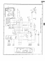
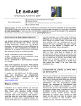
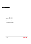
FLUORESCENT
r
*
-
HJZ.J3
DISPLAY
TUBE
IF “OT 5PCCIFIEO.,,5ZIOR
- i ,FwoT
SPECIFIEO.oTllVILS
COI”IIIG S”PPLL”L”T
-I--l--l-CT-‘?---+
L+
DOOR5”.
I
-
‘Ly3-i
*e
ORW.3”.
1
LIVE”TEW
-
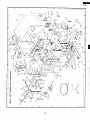
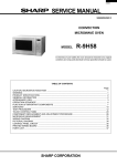
Figure
I
-
I
S-2.
Control
Panel
I
Circuit
-
(R-9A52)
I
R -9A52-7
R-9H52
1
2
3
4
5
6
2
ix
!k
.=
2
5
5
5
n
”
-E
E
6
5
3
:.
+
v)
2!
.-iz
IA
!:
:-.
0
E
s:
_-- ::
-- E
1
-au I
,I ,
: I
4
3-j
Iz
D
BY
t:
z
i;
E
z
IIu
,z/“zz
013
*
a;
9B
1%
9I
t
>
E
.
:
:d
-L ‘D r. c
“;E:
z 0 Lx ;
- d 2 :
d d d
“YYY
*c”
:::xt:
%5%:,
d
f
:!
y
t
4
XT
gzg
T:‘pY
OWL
x
:u
o>
j:
: :
i
f
5
5
v
--
L
c
L
-
::
;
::
”
:
r
*R::
--riA:,
ZI
;;
-“I
r.J
r-t-1
i,,::;
=
+::,
ci
‘b
L
11
--2
m’l:
m
f
R-9A52
R-9H52
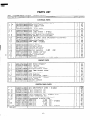
PARTS
Note :
The voltage supplied to the parts rr*n are greater than 250V.
REF. NO.
1
PART
NO.
l-
1
l- 2"
;I ;
l- 5
l- 6
l- 7
l- 8
l- 9
*
*
k
l-10
l-11
l-12
l-13
1-14
l-15
l-16
l-17
l-18
l-19
l-20
l-21
l-22
l-23
-
1
2
3
4
5
6
High voltage rectifier ass'y
Thermistor
ass'y
Power supply cord
Fuse (M8A)
Temp. fuse 150°C
Fuse holder
Oven lamp socket : R-9H52
Oven lamp socket : R-9A52
Monitor switch (V-5220D-070)
Stop switch (V-ll-3C25(RB))
QSW-MA051WREO
RC-QZA097WREO
RHET-A048WREO
RLMPTA029WREO
RLMPTA029WREO
RMOTDA043WREO
RMOTDA097WREO
RMOTEAO17WREO
RMOTEA124WREO
RR-WZA003WREO
RTHM-A024WREO
RTHM-A035WREO
RTRN-A318WREO
RV-MZA074WREO
FDTCTA095WRKO
Upper & lower latch switches(V-5230D-600)
High voltage capacitor
Convection
heater
Oven lamp : R-9H52
Oven lamp : R-9A52
Damper motor
Turntable motor
Cooling fan motor
Convection
motor
Monitor resistor
O.Sn
2ow
Oven therm0 cut-out
Fan therm0 cut-out
Power transformer
Magnetron
AH sensor assembly
: R-9H52 only
$1 ;
2- 9
2-10
2-11
2-12
2-13
2-14
FDAI-A095WRYO
FHNG-A092WRMO
GCABDA037WRWO
GCABUA277WRPO
GCOVHA156WRPO
GFTARAOOlWRWO
GLEGPA013WREO
LANGK0243WRPO
LBSHC0032WREO
LSTPP0008YBFO
LSTPP0009YBFO
MLEVPA122WRFO
PCUSGA023WRPO
PHOK-A043WRFO
AQ
1
1
1
1
2
1
1
2
it;
AE
AG
AE
AH
AH
AF
AE
2
1
AF
AW
AW
AK
AK
2'
1
1
1
1
1
1
1
1
1
1
1
AQ
AV
AW
AV
AG
AG
AG
BP
BG
AY
PARTS
1
1
1
1
1
Base plate assembly
Oven hinge (lower)
Rear cabinet
Outer case cabinet
Turntable motor cover
Oven lamp access cover
Foot
Capacitor holder
Cord bushing
Cord anchorage
(upper)
Cord anchorage
(lower)
Latch lever
Cabinet cushion
Latch hook
CONTROL
ICODE
PARTS
FH-DZAOOSWREO
FH-HZAOlOWREO
QACCAA020WREO
QFS-CAOlOWREO
QFS-TA013WREO
QFSHDA002WREO
QSOCLAOllWREO
QSOCLAOllWREO
QSW-MA009WREO
QSW-MA037WREO
CABINET
222222-
1 QJTY
DESCRIPTION
I
ELECTRICAL
*;
LIST
PANEL
PARTS
;
1
1
1
1
1
1
1
AW
AF
ATa
BA
AB
AC
AB
AC
AB
AC
AC
AD
AA
AM
-
3- 1
CPWBFA391WRKO
CPWBFA392WRKO
3- 1A
QCNCMA244DREO
3- 1B
QCNCMA230DREO
3- 1c
QCNCMA267DREO
3- 1D
QCNCMA090DREO
3- 1E
QCNCWA030DREO
3- 1F
QLUGPA004DREO
3- 1G
RV-KXA012DREO
Cl,21
RC-KZA032DREO
22
VCEAB31VW477M
22
RC-EZA192DREO
23,81
VCEAB31HW335M
25
VCEAB31CW476M
26,7,20,VCKYDllCYl03N
C60,61
(Not Replaceable
Item)
: R-9A52
(Not Replaceable
Item) : R-9H52
2-pin connector
(A)
4-pin connector
(B)
6-pin connector
(E)
3-pin connector
(F) : R-9H52 only
12-pin connector
(G)
Tab terminal
(TABl,TAB2,TAB3)
Fluorescent
display tube
Capacitor
O.lpF 5OV
Capacitor
47OpF
35V : R-9A52
Capacitor
1000j~F 35V : R-9H52
Capacitor
3.3pF 50V
Capacitor
47pF 16V
Capacitor
O.OlpF
16V : R-9A52
12
::
1
1
1
3
2'
1
1
2
1
5
AB
AC
AC
AB
AE
AA
AX
AB
AC
AD
AA
AA
AA
I
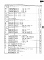
R-9A52
R-9H52
Note :
The voltage
REF. NO.
C6,7,20
c51,5
C60,6
C8
C8,50
Cl0
c53
c70
C80
CFl
Dl-5
D7,70,
D80-88
D93-99
D7,51,
D52,70
D80-88
D93-99
ICl
IC2
21
220,40
Q84-81
g
Q80
Q8l
Q82,83
Rl
R2
R2
R3,60,
R70,80
R4
R4
R5,20
R6
RlO
R14
R15
240,
R93-10.
350
251
352
153
154
x55
161
162
?63
t64
?81,86
2200
?Y1,4-6
{Y2
XY3
jP40
Cl
7RSl
!Dl
!D3
3- 2
I331I-
3
4
5
6
7
1
supplied
PART
to the parts r*n are greater than 250V.
NO.
I
DESCRIPTION
VCKYDllCY103N
Capacitor
O.OlpF
16V
: R-9H52
RC-KZA031DREO
RC-KZA031DREO
Capacitor
Capacitor
O.lpF
O.lpF
25V
25V
: R-9A52
: R-9H52
Q’TY
COD
a 7
VCEAB31EW226M
Capacitor
22pF 25V
VCKYBllEX153N
Capacitor
O.OlSpF
25V
VCKYF31HF103Z
Capacitor
O.OlpF
5OV
VCEAB31HW474M
Capacitor
0.47r.rF 5OV
RCRS-AOlODREO
Ceramic filter (4.00MHz)
VHDlSR139-11B
Diode (lSR139-100)
VHDlSS270A/-1Diode
(lSS270A) : R-9A52
5
18
AD
AA
AA
VHDlSS270A/-1
20
AA
1
1
AV
AD
AC
AB
Diode
(lSS270A)
2
AA
: R-9H52
-.
RH-IZA340DREO
VHIBA4558//-4
VS2SB793///-4
VSDTA143ES/lB
LSi
IC BA4558
Transistor
Transistor
: R-9H52 only
2SB793 : R-9H52
DTA143ES
RH-TZA063DREC
VSDTC114ES/-3
VSDTD143EA/-4
VSDTA114YS/-3
RH-TZA097DREO
VRD-B12EF471J
VRD-B12EF241J
VRD-B12HF331J
VRD-B12EF102J
Transistor
Transistor
Transistor
Transistor
Transistor
Resistor
Resistor
Resistor
Resistor
2SA933S
DTC114ES
DTD143EA
DTA114YS
DTB143ES
4700 1/4w
24On 1/4W
33On 1/2W
lk0 1/4w
1
only
5
1
1
1
1
2
: R-9H52
: R-9A52
: R-9H52
1
1
only
4'
VRD-B12EF182;
VRD-B12HF751;
VRD-B12EF153;
VRD-B12HF112;
VRD-B12HF360;
VRD-B12EF163;
VRD-B12EF622;
VRD-B12EF332;
Resistor
Resistor
Resistor
Resistor
Resistor
Resistor
Resistor
I
'Resistor
RR-DZA069DREC
VRS-B13AA331;
VRN-B12EK182E
gRN-B12EK364E
JRD-B12EF103,
JRD-B12EF473J
JRD-B12EF273J
JRN-B12EK753F
JRN-B12EKlOlF
JRN-B12EK222F
JRD-B12EF680J
IRD-B12EFlOSJ
?RLY-A020DREO
.tRLY-AOGlDREO
RRLY-A013DREC
RALM-A007DREC
xTRNPA023DREC
ZH-VZAOlODREC
JHEHZlGl///-1
ZH-EZAlOSDREC
"PNLCA840WRKO
TPNLCA841WRKO
TBTN-A606WRFO
Resistor
Resistor
Resistor
Resistor
360kR (F) 1/4W : R-9H52 only
Resistor
1OkR 1/4w : R-9H52 only
Resistor
47kR 1/4w : R-9H52 only
Resistor
27kn 1/4w
Resistor
75kO (F) 1/4W
Resistor
1000 (F) 1/4W
Resistor
2.2kn (F) 1/4W
Resistor
68R 1/4w
Resistor
1MR 1/4W
Relay (OJSH112LM)
Relay (OMI-SH112D,WHITE)
Relay (OMI-SH112D,BLUE)
Buzzer (PKM22EPT)
Transformer
Varistor
(15G471K)
Zener diode (HZ16-1) . R-9H52 only
Zener diode (RD4.3ESB2)
Control panel frame with key unit : R-9A52
Control panel frame with key unit : R-9H52
Open button
ISPRDA009WREO
JANGTA197WRWO
llLEVFAO42WRWO
JSFTTA030WREO
Open button spring
Control panel back
Open lever
Open shaft
1.8kn
75022
15kfi
l.lkO
36n
16KQ
6.2Kn
3.3kS2
block
1/4W
1/2W
1/4w
1/2W
1/2W
1/4w
1/4W
1/4w
: R-9A52
: R-9H52
i
2
: R-9A52
only
: R-9A52
: R-9A52
only
only
: R-9H52 only
3300 1w : R-9H52 only
1.8kR (F) 1/4W : R-9H52
13
AB
AB
AC
AB
AC
AA
AA
AA
AA
AA
1
1
.i
only
12
AA
1
AD
::
::
1
::
AA
AA
A
3
AK
AF
AR
AE
AA
AA
AZ
AZ
AC
AA
plate
AK
AC
AB
/
R-9A52
R-9H52
Note :
The voltage supplied
REF. NO.
3- 8
3- 9
PART
XEPSD30P12XSO
XCPSD40P12000
4- 5
4- 6
;r ;
4- 9
4-10
4-11
4-12
4-13
4-14
4-15
4-16
4-17
4-18
4-19
4-20
4-21
4-22
4-23
4-24
4-25
4-26
4-27
4-28
4-29
4-30
4-31
4-32
4-33
4-34
4-35
4-36
4-37
4-38
4-39
4-40
4-41
4-42
4-43
4-44
4-45
4-46
FBRGMA002WREO
FDUC-A124WRWO
FDUC-A126WRWO
FFANJ0034WRKO
FFTA-A022WRKO
FOVN-A227WRTO
FOVN-A144WRYO
FROLPA045WRKO
LANGFA089WRWO
LANGQA136WRWO
FANGQAlllWRYO
LANGQA213WRWO
LANGQA163WRPO
LANGTA196WRWO
LBNDK0054WREO
LFIX-A013WRWO
LHLDKOOOSYBFO
MCAMPA030WRFO
MHNG-A165WRMO
NBLTKAOOSWREO
NCPL-A021WRFO
NFANMA019WRWO
NPLYBA025WRFO
NPLYBA025WRFO
NSFTTA043WREO
NTNT-A019WRHO
PCOVPA157WREO
PCOVPA167WRFO
PCUSGA211WRPO
PCUSUA146WRPO
PCUSU0263WRPO
PCUSU0329WRPO
PCUSU0380WRPO
PDUC-A267WRPO
PDUC-A269WRWO
PDUC-A270WRFO
PFPF-A138WREO
PREFHA028WRPO
PFPF-A139WREO
PGLSPA181WREO
PREFHA027WRPO
PSKR-AlSlWRWO
PSKR-A152WRPO
PSKR-A153WRPO
PSKR-A156WRPO
PSKR-AlGlWRWO
PSKR-A171WRPO
PCUSGA221WRPO
PFPF-A064WREO
Screw;control
Screw;control
unit mtg.
panel back plate
5- 1
5- 2
5- 3
;I ;
5- 6
55: ;
5- 9
CDORFA490WRKO
CDORFA491WRKO
DDORFA262WRYO
GCOVHAlSSWRFO
GWAKPA142WRFO
HDECQA123WRFO
HDECQA124WRFO
LSTPPA045WRFO
LSTPPA046WRFO
MSPRTA007WREO
NSFTTA044WREO
mtg.
Door
Door
Door
Choke
Door
Door.
Door
Upper
Lower
Latch
Latch
3
4
CODE
AB
AA
PARTS
Bearing assembly
Steam duct assembly
: R-9H52
Steam duct assembly
: R-9A52
Cooling fan assembly
Damper assembly
Oven cavity : R-9H52
Oven cavity : R-9A52
Roller stay
Chassis support
Convection
motor mounting plate
Lamp socket mounting angle : R-9H52
Lamp socket mounting angle : R-9A52
Thermal cut-out mounting angle
Bearing mounting plate
Heater element holder
Bearing holder plate
Cord holder
Damper cam
Oven hinge (upper)
Convection
fan belt
Turntable
coupling
Convection
fan
Pulley (M)
Pulley (M)
Damper shaft
Turntable tray
Waveguide
cover
AH sensor cover :R-9H52 only
Transformer
cushion D
Magnetron
duct cushion
Cushion
Cushion
Steam cushion C
Heater duct
Damper duct
Cooling fan duct
Thermal protection
sheet (left)
Thermal protection
plate (left)
Thermal protection
sheet (right)
Oven lamp screen
Thermal protection
plate (right)
Air guide (A)
Air guide (B)
Air guide (bottom)
Air guide (C)
Air guide (right)
Magnetron
air guide
Cushion
Thermal protection
sheet
DOOR
5
Q’TY
DESCRIPTION
NO.
OVEN
4- 3
4- 4
.
to the parts rr*r are greater than 250V.
1
AQ
:
1
1
AN
AN
AF
AE
:
1
1
1
1
1
1
1
2
i
1
1
1
;
:
1
1
1
::
1
3
1
2
1
1
1
i
1
1
1
i
::
1
1
1
1
BV
BQ
AP
AE
AE
AK
AE
AB
AD
AB
AB
AB
AC
AE
AF
AE
AE
AC
AC
AA
AT
AD
AC
AB
AA
AA
AA
AA
AN
AK
AL
AK
AM
AF
AG
AL
AD
AB
AF
AB
AF
AD
AB
AE
PARTS
assembly, complete
assembly,
complete
panel
cover
frame
sash (right)
sash (left)
latch head
latch head
spring
shaft
14
: R-9H52
: R-9A.52
1
t
1
1
1
t
9
1
BP
BP
BH
AP
AT
AF
AE
AB
AB
AB
AC
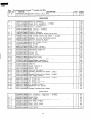
R-9A52
R-9H52
Note :
The voltage supplied
REF. NO.
S-10
PART
to the parts “*I’
are greater than 250V.
NO.
PGLSPA308WREO
PGLSPA309WREO
DESCRIPTION
Door
Door
glass
glass
Q’TY
: R-9H52
: R-9A52
CODE
1
1
BA
BA
1
1
1
1
1
AP
AP
AY
AG
AG
MISCELLANEOUS
6- 3
6- 4
:I 2
*
*
:I ;
6- 9
6-10
6-11
6-12
6-13
6-14
FAMI-A059WRMO
FAMI-A058WRMO
TCADCA348WRRO
TINSEA538WRRO
TINSEA539WRRO
High rack
Low rack
Cook book,Operation
manual
Operation
manual
LBNDK0012YBEO
FW-VZB023WREO
FW-VZA810WREO
QW-QZA099WREO
QW-QZAlOOWREO
Wire
Main
Main
High
High
FW-VZA591WREO
TLABSA018WRRO
LHLDWQOO4YBEO
QTANP0020YBEO
TCAUH0114WRRO
TSPCNB463WRRO
TSPCNB464WRRO
Thermistor
harness
Fuse label
Wire holder (purse lock
Connector
CE-230
Caution label
Name plate : R-9H52
Name plate : R-9A52
holder (WH-1 84mm )
wire harness
: R-9H52
wire harness
: R-9A52
voltage wire A
voltage wire B
SCREW,
7777-
1
2
3
4
: R-9H52
: R-9A52
LX-BZ0186WREO
Screw;
LX-BZ0202WREO
Screw;
LX-CZA020WREO
Screw;
LX-CZ0017WREO'Screw;
NUTS,
WASHERS
AND
oven lamp access cover mtg.
upper & lower latch heads mtg.
oven hingestupper
& lower) mtg.
heater element holders, thermister
air guide (A), (B) and (C) mtg.
7- 6
7- 7
7- 8
7- 9
7-10
7-11
7-12
LX-CZ0052WREO
XOTSD40R12RVO
LX-NZ0029YBEO
XBPSD30P14KOO
XBPSD40P06KOO
XBPSD40P25000
XFPSD40P30000
thermal protection
platecleft),
bearing holder plate and
convection motor assembly mtg.
Screw; latch hook mtg.
Screw; (LHSTIX LR-4) outer case cabinet
Nut; steam duct assembly mtg.
Screw; damper switch mtg.
Screw; convection motor assembly mtg.
Screw; cooling fan motor mtg.
Screw; cord anchorages
mtg.
7-13
XBTUW40P06000
Screw;
7-14
XBTWW40P06000
7-15
XCPSD30P06000
7-16
7-17
7-18
7-19
LX-WZA004WREO
XCPSD30P08XOO
XCPSD30P08000
XCPSD40P08000
7-20
7-21
7-22
XCTSD40P08000
XFPSD30P08000
XFPSD40P08KOO
7-23
7-24
7-25
XFPSD40P08000
XFPSDGOP14JSO
XNESD40-32000
7-26
7-27
T-28
XNEUW40-32000
XOTSE40P12000
LX-CZ0047WREO
assembly
mtg.
waveguide
cover mtg.heater
unit assembly,
steam duct,over
lamp mounting angle.
Screw; bearing mounting plate and $
convection heater mtg.
Screw; damper motor, oven therm0 cut-out
and fan therm0 cut-out mtg.
Washer; bearing mounting plate mtg.
Screw; door frame and door sash(left) mtg.
Screw; door frame mtg.
Screw; door sashcright),
thermal protection
platecright),
air guidetright)
and damper assembly mtg.
Screw; steam
duct mtg.
Screw; AH sensor assembly mtg. : R-9H52 only
Screw; oven lamp mounting
angle,
high voltage rectifier
assembly,
MG air guide(K) and
thermistor
harness grounding mtg.
Screw; turntable motor and magnetron mtg.
Screw; power transformer
mtg.
Nut; cooling fan motor and
upper & lower latch heads mtg.
Nut; convection
fan mtg.
Screw; outer case cabinet mtg.
Screw; base plate, T/C panel and
chassis support mtg.
outer case cabinet, cord
and chassis support mtg.
15
1
2
6
8
AA
AB
AA
AA
6
Ai4
PINS
Screw;
Screw;
AC
AC
"L")
LX-CZ0043WREO
XOTSD40P12000
1
1
1
1
7- 5
r-29
\
:
1
AA
AZ
AX
AD
AD
AM
AB
AA
AA
AC
::
1
1
1
holder
2
2
1
1
2
2
2
13
AA
AA
AA
AA
AA
AA
AA
AA
4
AA
5
AA
6"
3
7
AA
AA
AA
AA
2'
4
AA
AA
AA
5
2
4
AA
AA
AA
11
AA
7
AA
’
*
R-9A52
R-9H52
Note:
The voltage
REF. NO.
supplied
PART
to the parts r*M are greater than 250V.
DESCRIPTION
NO.
Q’TY
CODE
7-30
7-31
7-32
7-33
7-34
XWSUW40-10000
XWWSD~O-08000
XFPSD30PlOOOO
LX-WZA022WREO
XBPSD40P08KOO
Washer; convection
fan mtg.
Washer; power transformer
mtg.
Screw; fuse holder mtg.
Washer; turntable motor mtg.
Screw; power supply cord grounding
1
1
AA
AA
AA
AA
AA
7-35
XFTSD40P08TVO
Screw;
4
AA
7-36
XOTSD40P08000
4
AA
1
1
1
high voltage rectifier
assembly,
convection
motor assembly, monitor
resister, turntable motor covering,
Screw; rear cabinet
HOW TO ORDER REPLACEMENT
To have your order filled
promptly
and correctly,
1. MODEL NUMBER
3. PART NO.
16
_
_
-.
.-_
.
I
PARTS
please furnish
the following
2. REF. NO.
4. DESCRIPTION
information.
1
R-9A52
R-SH52
1
2
3
4
5
I
7
c
P
A
8
8
C
C
D
D
E
E
F
F
G
G
H
H
I
-
17
R-SA52
R-SH52
2
1
DOOR
3
PARTS
-
4
5-2
P
CONTROL
5
6’
PAN EL PARTS
A
/
,’
fH.V ‘2)
MISCELLANEOUS
IMG.)
D
II
IH v C)
iH,V.T)
E
E
x Actual
F
wire
harness
may
be dlfferent
than
lllustratlon
PACKING AND ACCESSORIES
F
PACKING ADD KiT
DOOR PROTECTION SHEET
G
G
H
H
%Not replaceble items
IL
1
I
2
I
7
I
I
n
I
I
5
‘91 0 SHARP CORP. (1 U0.75E)
18
--
6
-1
Printed in Japan