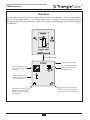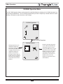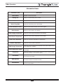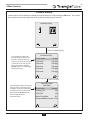
1
prestige
User s Information Manual
If the information in this manual is not followed exactly, a fire or explosion may
WARNING result causing property damage, personal injury or loss of life.
FOR YOUR SAFETY
•
Do not store or use gasoline or other flammable vapors and liquids in the vicinity of this or
any other appliance.
•
WHAT TO DO IF YOU SMELL GAS
- Do not try to light any appliance
- Do not touch any electrical switch; do not use any phone in your building.
- Immediately call your gas supplier from a neighbor’s phone. Follow the gas supplier’s
instructions.
- If you cannot reach your gas supplier, call the fire department.
Installation and service must be performed by a qualified installer, service agency or the gas
supplier.
Revised 3/1/13
2011-58 Prestige User’s Manual
Table of Contents
PRODUCT & SAFETY INFORMATION
Page 1
Service and Maintenance
PRESTIGE Operation
Boiler & System Water
SECTION I - Combustion Air - Prevention of Contamination
Page 2
Potential Contaminating Products
Areas likely to find these Products
SECTION II - Maintenance Schedule
Page 3
Service Technician
Owner Maintenance
SECTION III - Maintenance Procedures
Page 4
Daily Maintenance
Monthly Maintenance
6-Month Maintenance
SECTION IV - Operations Instructions
Page 7
SECTION V - TriMax Operation
Page 8
Replacement Parts
Page 20
The following terms are used throughout this manual to bring attention to the presence of potential hazards or
to important information concerning the product.
NOTICE
WARNING
Indicates a potentially hazardous situation,
which if ignored, can result in death, serious
injury or substantial property damage.
Indicates special instructions on installation,
operation or maintenance, which are important to
equipment but not related to personal injury hazards.
CAUTION
Indicates a potentially hazardous situation
which, if ignored, may result in minor injury or
property damage.
i
Product & Safety Information
PRESTIGE Operation
PRODUCT & SAFETY INFORMATION
•
Do not block flow of combustion air to the PRESTIGE. If the combustion air blockage is easily
accessible and removable, then remove it. If blockage is not obvious or cannot be removed, have the
unit and system checked by a qualified service technician.
•
Do not allow contaminated air to enter the unit’s
combustion air inlet. See page 2 for details.
•
The PRESTIGE is equipped with a low water cutoff
device. The boiler and system piping must be filled
and pressurized to 12 psig prior to startup. The unit
will shut down if the pressure falls below 10 psig.
•
Should overheating occur or the gas supply fail to
shut off, DO NOT turn OFF or disconnect the electrical supply to the pump. Instead, shut off the gas
supply at a location external to the appliance.
•
Do not use this unit if any part has been under water.
Immediately call a qualified service technician to
inspect the boiler and to replace any part of the control system and any gas control, which has been
under water.
WARNING
HOMEOWNER: The PRESTIGE installation manual is
for use only by a qualified heating installer / service
technician. Refer to this User’s Information Manual
for your reference. Failure to comply could result in
severe personal injury, death or substantial property
damage.
NOTICE
TECHNICIAN: When calling or writing about the
PRESTIGE, please have the boiler model and serial
number available.
STOP! READ BEFORE SERVICING
WARNING
Boiler & System Water
Failure to adhere to the guidelines on this page can
result in severe personal injury, death or substantial
property damage.
•
Have the boiler and system water chemistry
checked at least annually by a qualified service technician.
•
Do not use petroleum-based cleaning or sealing
compounds in the boiler or system. Gaskets and
seals in the system may be damaged. This can
result in substantial property damage.
•
Do not use any product not specifically designed for
boiler / hydronic heating systems. Serious damage
to the unit, piping system, personnel and / or property may result.
•
Continual fresh makeup water will reduce the life of
the PRESTIGE. Addition of oxygen can cause internal corrosion in the system components. All leaks in
the piping system must be repaired at once to prevent makeup water.
•
Do not add cold water to a hot unit. Thermal shock
can cause premature failure to the boiler heat
exchanger.
Service and Maintenance
•
To avoid electric shock, disconnect electrical supply
before performing service or maintenance.
•
Allow the unit to cool down prior to servicing to avoid
severe burns.
•
The PRESTIGE must be maintained as outlined in
this manual and have at least annual service performed by a qualified service technician to ensure
unit / system reliability.
1
Combustion Air - Prevention of Contamination
SECTION I - COMBUSTION AIR - PREVENTION OF
CONTAMINATION
Potential Contaminating Products
WARNING
If the PRESTIGE combustion air inlet is located in
any area likely to cause or contain contamination, or
if products, which would contaminate the air cannot
be removed, the combustion air must be re-piped
and terminated to another location. Contaminated
combustion air will damage the unit and its burner
system, resulting in possible severe personal injury,
death or substantial property damage.
WARNING
Do not operate a PRESTIGE unit if its combustion air
inlet or the unit is located in or near a laundry room
or pool facility. These areas will always contain hazardous contaminates.
Pool and laundry products and common household
and hobby products often contain fluorine or chlorine compounds. When these chemicals pass
through the burner and vent system, they can form
strong acids. These acids can create corrosion of
the heat exchanger, burner components and vent
system, causing serious damage and presenting a
possible threat of flue gas spillage or water leakage
into the surrounding area.
-
Spray cans containing chloro/fluorocarbons
-
Permanent Wave Solutions
-
Chlorinated wax
-
Chlorine - based swimming pool chemicals and
spa cleaners
-
Calcium Chloride used for thawing ice
-
Sodium Chloride used for water softening
-
Refrigerant leaks
-
Paint or varnish removers
-
Hydrochloric acid / muriatic acid
-
Cements and glues
-
Antistatic fabric softeners used in clothes dryers
-
Chlorine-type bleaches, detergents, and cleaning solvents found in household laundry rooms
-
Adhesives used to fasten building products and
other similar products
Areas likely to find these products
Please read the following information. If contaminating chemicals will be present near the location of
the combustion air inlet, the installer should pipe the
combustion air inlet to another location per the
PRESTIGE installation manual.
2
-
Dry cleaning / laundry areas and establishments
-
Beauty salons
-
Metal fabrication shops
-
Swimming pools and health spas
-
Refrigeration Repair shops
-
Photo processing plants
-
Auto body shops
-
Plastic manufacturing plants
-
Furniture refinishing areas and establishments
-
New building construction
-
Remodeling areas
-
Garages with workshops
Maintenance Schedule
SECTION II - Maintenance Schedule
Owner Maintenance
Service Technician
Periodically:
At least on an annual basis the following maintenance
should be performed by a qualified service technician:
-
Check the area around the unit.
-
Check and remove any blockage from the combustion air inlet and ventilation openings.
-
Check the temperature/pressure gauge.
General
-
Attend to any reported problems.
-
Inspect the interior of the boiler jacket area; clean
and vacuum if necessary.
-
Clean the condensate trap and fill with fresh water.
-
Check boiler water pH on systems with inhibitors
and/or antifreeze.
-
Monthly:
-
Check vent piping.
-
Check combustion air inlet piping.
-
Check the pressure relief valve.
Check for leaks: water, gas, flue and condensate.
-
Check the condensate drain system.
-
Verify flue vent piping/gaskets and air inlet piping are
in good condition, sealed tight and properly supported.
Every 6 months:
-
Check boiler water pressure, piping and expansion
tank.
-
Check boiler piping and gas supply piping for corrosion or potential signs of leakage.
-
Check control settings.
-
Operate the pressure relief valve.
-
Check ignition electrode (sand off any white oxide;
clean and reposition).
-
Check ignition wiring and ground wiring.
-
Check all control wiring and connections.
-
Check burner flame pattern (stable and uniform).
WARNING
Follow the maintenance procedures given
throughout this manual. Failure to perform the
service and maintenance or follow the directions
in this manual could result in damage to the
PRESTIGE or in system components, resulting
in severe personal injury, death or substantial
property damage.
Additional items if combustion or performance is
poor:
-
Clean heat exchanger and flue ways.
-
Remove burner assembly and clean burner head
using compressed air only.
Once the maintenance items are completed, review the
service with the owner.
3
Maintenance Procedures
SECTION III - MAINTENANCE PROCEDURES
1. Combustible / flammable materials - Do not
store combustible materials, gasoline or other
flammable vapors or liquids near the unit.
Remove immediately if found.
WARNING
2. Air contaminates - Products containing chlorine
or fluorine, if allowed to contaminate the combustion air, will cause acidic condensate within
the unit. This will cause significant damage to
the unit. Read the list of potential materials listed on page 2 of this manual. If any of these
products are in the room from which the unit
takes its combustion air, they must be removed
immediately or the combustion air intake must
be relocated to another area.
The PRESTIGE must be inspected and serviced
annually, preferably at the start of the heating season, by a qualified service technician. In addition,
the maintenance and care of the boiler as outlined
on page 3 and further explained on pages 4 through
6 must be performed to assure maximum efficiency
and reliability of the unit. Failure to service and
maintain the PRESTIGE and the system components
could result in equipment failure, causing possible
severe personal injury, death or substantial property
damage.
Check Combustion Air Inlets
1. Verify that ventilation air openings to the
mechanical room are open and unobstructed.
NOTICE
2. Verify that the unit’s vent termination and combustion air intake are clean and free of obstructions. Remove any debris on the air intake or
flue exhaust openings. If removing the debris
does not allow the unit to operate correctly, contact your qualified service technician to inspect
the unit and the vent / combustion air system.
The following information provides detailed instruction for completing the maintenance items outlined
in the maintenance schedule on page 3. In addition
to this maintenance, the PRESTIGE should be serviced at the beginning of the heating season by a
qualified service technician.
Check Temperature Display and Pressure Gauge
Daily Maintenance
Check the Surrounding Area
1. Ensure the pressure reading on the pressure
gauge does not exceed 25 psig. Higher pressure readings may indicate a problem with the
expansion tank.
WARNING
2. Ensure the temperature on the display panel
does not exceed 194ºF. Higher temperature
readings may indicate a problem with the operating thermostat controls.
To prevent potential of severe personal injury, death
or substantial property damage, eliminate all the
materials listed on page 2 from the area surrounding
the unit and from the vicinity of the combustion air
inlet. If contaminates are found:
3. Contact a qualified service technician if problem persists.
Remove products immediately from the area. If they
have been there for an extended period, call a qualified service technician to inspect the unit for possible damage from acid corrosion.
If products cannot be removed, immediately call a
qualified service technician to re-pipe the combustion air inlet piping and locate the combustion air
intake away from the contaminated areas.
4
Maintenance Procedures
Monthly Maintenance
WARNING
Check Vent Piping
Under some circumstances the PRESTIGE may not
produce enough condensate to keep the condensate
trap full of liquid. If the trap is not full, small
amounts of flue gases can be emitted into the surrounding area through the condensate drain line or
tee.
1. Visually inspect the flue gas vent piping for any
signs of blockage, leakage or deterioration of
gaskets. Notify a qualified service technician
immediately if any problems are found.
3. Ensure the condensate drain line is not blocked
by pouring water through the plug port on the
condensate drain assembly. The water should
flow out of the end of the drain line. If water
does not appear at the end of the drain line, contact a qualified service technician to inspect and
clean the condensate line.
WARNING
Failure to inspect the venting system as noted and
have it repaired by a qualified service technician can
result in the vent system failure, causing severe personal injury or death.
4. To fill the condensate drain assembly, if necessary, remove the plug from the condensate
assembly. Slowly pour water into the trap
assembly until water appears at the end of the
drain line. Stop filling and replace plug.
Check Combustion Air Inlet Piping
1. Visually inspect the combustion air inlet piping for
any signs of blockage. Inspect the entire length
of the combustion air inlet piping to ensure piping
is intact and all joints are properly sealed.
Check Automatic Air Vents (If Used)
1. Remove the cap “A” from any automatic air vent
in the system and check operation by depressing
valve “B” slightly with the tip of a screwdriver. See
Fig. 1.
2. Notify a qualified service technician if any problems are found.
Check Pressure Relief Valve
2. If the air vent valve appears to be working freely
and not leaking, replace cap “A”, screwing it on
fully.
1. Visually inspect the primary pressure relief valve
and the relief valve discharge pipe for signs of
weeping or leakage.
3. Loosen cap “A” one full turn to allow vent to
operate properly.
2. If the pressure relief valve often weeps, the
expansion tank may not be operating properly.
Immediately contact a qualified service technician to inspect the unit and system.
4. Have the air vent replaced by a qualified service
technician if it does not operate correctly.
Check Vent Condensate Drain System
A
1. While the unit is running, check the discharge
end of the condensate drain tubing. Ensure no
flue gas is leaking from the condensate drain
tubing or tee connection by holding your fingers
near the opening.
2. If you notice flue gas leaking from the opening,
this indicates a dry condensate drain trap. Fill
the condensate trap assembly. Contact a qualified service technician to inspect the unit and
condensate line and refill the condensate trap if
problem persists regularly.
B
Fig. 1: Automatic Air Vent
5
Maintenance Procedures
2. Read the temperature display and pressure
gauge to ensure the system is pressurized. Lift
the relief valve top lever slightly, allowing water to
relieve through the valve and discharge piping.
6-Month Maintenance
Check Water and Gas Piping
3. If water flows freely, release the lever and allow
the valve to seat. Watch the end of the relief
valve discharge pipe to ensure that the valve
does not weep after the line has had time to
drain. If the valve weeps, lift the lever again to
attempt to clean the valve seat. If the valve
does not properly seat and continues to weep
afterwards, contact a qualified service technician to inspect the valve and system.
1. Remove the boiler front jacket panel and perform a
gas leak inspection per steps 1 through 6 of the
Operating Instructions on page 7. If gas odor or
leak is detected, immediately shut down the unit
following procedures on page 7. Call a qualified
service technician.
2. Visually inspect for leaks around the internal boiler
water connections and around the heat exchanger.
Visually inspect the external system piping, circulators, and system components and fittings.
Immediately call a qualified service technician to
repair any leaks.
4. If the water does not flow from the valve when
you lift the lever completely, the valve or discharge line may be blocked. Immediately shut
the unit down per the instructions on page 7.
Call a qualified service technician to inspect the
valve and system.
WARNING
Have leaks fixed at once by a qualified service technician. Failure to comply could result in severe personal injury, death or substantial property damage.
Operate Pressure Relief Valve
1. Before proceeding, verify that the relief valve
outlet has been piped to a safe place of discharge, avoiding any possibility of scalding from
hot water.
WARNING
To avoid water damage or scalding due to valve
operation, a discharge line must be connected to the
relief valve outlet and directed to a safe place of disposal. This discharge line must be installed by a
qualified service technician or heating / plumbing
installer in accordance with the PRESTIGE installation manual. The discharge line must be terminated
so as to eliminate possibility of severe burns or
property damage should the valve discharge.
6
Operating Instructions
SECTION IV - OPERATING INSTRUCTIONS
FOR YOUR SAFETY READ BEFORE LIGHTING
WARNING
If you do not follow these instructions exactly, a fire or explosion may result causing property damage, personal injury or loss of life.
A.
This appliance does not have a pilot. It is equipped with
an ignition device which automatically lights the burner.
DO NOT try to light the burner by hand.
B.
BEFORE OPERATING, smell all around the appliance
area for gas. Be sure to smell next to the floor because
some gas is heavier than air and will settle on the floor.
• If you cannot reach your gas supplier, call the fire
department.
WHAT TO DO IF YOU SMELL GAS
• Do not try to light any appliance.
C.
Use only your hand to turn the external manual gas
valve. Never use tools. If the valve will not turn by hand,
don’t try to repair it; call a qualified service technician.
Force or attempted repair may result in a fire or explosion.
D.
Do not use this appliance if any part has been under
water. Immediately call a qualified service technician to
inspect the appliance and to replace any part of the
control system and any gas control which has been
under water.
• Do not touch any electric switch; do not use any
phone in your building
• Immediately call your gas supplier from a neighbor’s
phone. Follow the gas supplier’s instructions.
OPERATING INSTRUCTIONS
1.
STOP! Read the safety information above. This appliance is equipped with an ignition device which automatically lights the burner. DO NOT try to light the burner by hand.
2.
Set room thermostat(s) to lowest setting. Turn the
external manual gas valve handle clockwise
“CLOSE” (valve handle shall be perpendicular to gas
piping).
3.
Turn the service switch on the PRESTIGE control panel
OFF.
4.
Remove the front jacket panel on the unit.
5.
Turn the external manual gas valve handle counter
clockwise
to “OPEN” gas supply (valve handle
shall be parallel to gas piping).
6.
Wait five (5) minutes to clear out any gas. If you then
smell gas in the jacket enclosure or around the unit,
STOP! Follow “B” in the safety information above. If you
don’t smell gas, go to the next step.
7.
Turn the service switch on the PRESTIGE control panel
“ON”.
8.
Set room thermostat(s) to desired setting(s).
9.
The PRESTIGE control panel display will show the current operating status on the Status Line at the bottom of
the screen. “Standby” means there is no call for heat (all
thermostats are satisfied). “CH Demand” indicates a
space heating call has been received. “DHW Demand”
indicates a domestic hot water call has been received. A
flame icon will be displayed when the unit is fired.
10. If the unit will not operate with a call for heat and the system piping is not hot, follow the instructions “To Turn Off
Gas to Appliance”, below and call your service technician
or gas supplier.
11. Replace the front jacket panel. Make sure the panel is seated firmly in place and all mounting screws are tightened.
TO TURN OFF GAS TO APPLIANCE
1.
Set the room thermostat to lowest setting.
2.
Turn the service switch on the PRESTIGE control panel
to “OFF”
3.
7
Turn the external manual gas valve handle clockwise
to “CLOSE”.
TriMax Operation
SECTION V - TRIMAx OPERATION
The TriMax Boiler Management System is designed to be flexible yet easy to use. TriMax monitors and controls the
Prestige to provide heat as efficiently as possible. All TriMax features are easy to use through a graphical display
where information is presented either graphically or in plain English, so code charts are not required.
Navigation is performed through four arrow buttons UP, DOWN, LEFT, RIGHT with a center OK button for making
selections and entering information. The INSTALLER button (the small round button) provides the installing contractor with full access to all available features after entering a password.
Figure 2 – TriMax Navigation Buttons
The Main Menu can be entered from the Home Screen by pressing the OK button. The menu system utilizes icons
to represent each selection. The current selected menu is displayed as a reversed image with a text description
shown at the top of the display. Menus can be entered by highlighting the desired icon and pressing the OK button.
The Home Screen
icon at the bottom of each screen returns to the Home Screen when selected. The Previous
Screen
icon at the bottom of each screen returns to the previous screen when selected.
8
TriMax Operation
TriMax Menu Structure
Home Screen
Main Menu
EZ Setup Menu
CH/DHW Operation Menu
Heating Enabled
Boiler Information Menu
Boiler Information
b bbb f
bbb b
bb f ed cebd cba
de f b b
ed cba a
abcc de f
ab d e
abc
b bbb f ed
bbb b
bb f ed cb cba
de f
a
abc de f bb
d cba gb
c
b
f
a d
abc
9
TriMax Operation
Home Screen
The Home Screen presents status information in a very user friendly way so that the current state of the boiler
can be quickly accessed.
The Prestige is represented in the center of the Home Screen. Basic operating
information such as supply and return temperatures are displayed as well as
current burner status. A flame symbol is displayed when the unit is fired. The
flame size changes to indicate the current firing rate.
The radiator icon indicates that a
central heating call has been received.
A small number 1 or 2 indicates
which CH calls are active.
1
2
Circulator icons indicate which
circulators are currently powered.
The faucet icon indicates that a
domestic hot water call has been
received.
This line provides basic information.
The user can press the LEFT or RIGHT
arrow buttons to view Target, Supply,
Return, Domestic and Outdoor
Temperatures.
The percentage icon indicates that
an external modulation call has
been received.
The status line displays the current operating state of the Prestige.
See page 11 for a list of all Status Line Messages.
The screen backlight will illuminate when any button is pressed and remain illuminated for five minutes. Press
the UP or DOWN buttons to turn on the backlight while at the Home Screen without making any changes.
The screen contrast can be adjusted at the Home Screen by pressing and holding the OK button then pressing
and holding the LEFT arrow along with the OK button. The contrast can then be increased by pressing the UP
button or decreased by pressing the DOWN button while holding in the OK button and LEFT arrow. All buttons
must be released and the procedure performed again to switch between increasing and decreasing contrast.
10
TriMax Operation
Status Line Messages
Status Line Message
Standby
CH Demand
DHW Demand
Description
Indicates that the Prestige is ready to respond when a demand is received.
A central heating call has been received.
A domestic hot water call has been received.
CH / DHW Demand
Central heating and domestic hot water calls are being received simultaneously.
Both calls are being satisfied simultaneously because domestic hot water priority
has been disabled.
DHW Priority
Central heating and domestic hot water calls are being received simultaneously.
Domestic hot water call is being satisfied first because it has priority over central
heating calls.
Priority Timeout
Central heating and domestic hot water calls are being received simultaneously.
The domestic hot water priority time limit has been exceeded. Priority will now
switch back and forth between central heating and domestic hot water calls until
one call is satisfied.
External Demand
An external modulation call has been received.
Slave Operation
The Prestige is a slave in a cascade system.
Manual Operation
The burner or circulators have manually been enabled in the Installer Menu.
CH Burner Delay
The burner will not fire until the call blocking time has elapsed.
DHW Burner Delay
The burner will not fire until the call blocking time has elapsed.
CH Setpoint Reached
DHW Setpoint Reached
The burner is not fired because the supply/system water temperature exceeds
the setpoint. The central heating circulator continues to operate and the burner
will fire again once the supply/system water temperature drops below the setpoint.
The burner is not fired because the supply/system water temperature exceeds
the setpoint. The domestic circulator continues to operate and the burner will fire
again once the supply/system water temperature drops below the setpoint.
CH Post Pump
The central heating circulator is running to remove heat from the Prestige at the
completion of a call.
DHW Post Pump
The domestic hot water circulator is running to remove heat from the Prestige at
the completion of a call.
Freeze Protection
The burner is fired because the freeze protection feature has been activated.
Freeze protection will end once the supply/system water temperature is raised to
60ºF [16ºC].
Boiler Protection
The burner firing rate is being reduced because of an excessive difference
between the boiler supply and return temperatures. The firing rate will begin
increasing once the temperature difference is less than 45ºF [25ºC].
Lockout Description
The lockout which currently has the Prestige shut down is displayed.
11
TriMax Operation
Main Menu
The Main Menu can be entered from the Home Screen by pressing the OK button. The menu system utilizes
icons to represent each selection. The currently selected menu is displayed as a reversed image with a text
description shown at the top of the display. Menus can be entered by highlighting the desired icon and pressing
the OK button.
Press OK Button
Currently selected menu
The CH / DHW Operation
Menu can be accessed by
selecting this icon.
The EZ Setup menu can
be accessed by selecting
this icon.
The Boiler Information
Menu can be accessed
by selecting this icon.
The Previous Screen icon at the
bottom of each screen returns to
the previous screen when selected.
The Home Screen icon at
the bottom of each screen
returns to the Home Screen
when selected.
12
TriMax Operation
CH/DHW Operation Menu
The CH / DHW Operation Menu can be entered from the Main Menu by selecting the CH / DHW Operation icon
and pressing the OK button. The CH / DHW Operation Menu provides a simple way to disable either the central
heating or domestic hot water functions of the Prestige.
CH/DHW Operation
Select CH/DHW Operation
Heating Enabled
Domestic Hot Water Operation
can be enabled and disabled by
selecting the faucet icon and
pressing the OK button to toggle
operation between enabled and
disabled. A faucet icon with an
X through it indicates that the
domestic hot water function is
disabled. This icon is also
displayed on the Home Screen
when disabled.
Heating Operation can be
enabled and disabled by
selecting the radiator icon
and pressing the OK button
to toggle operation between
enabled and disabled. A
radiator icon with an X
through it indicates that the
heating function is disabled.
This icon is also displayed
on the Home Screen when
disabled.
13
TriMax Operation
Boiler Information
Boiler Information can be viewed by selecting the Boiler Information icon and pressing the OK button. Boiler
Information provides real time operating information of the Prestige.
Boiler Information
b bbb f
bbb b
bb f ed cebd cba
de f b b
ed cba a
abcc de f
ab d e
abc
b bbb f ed
f bbb b
bb f ed cb cba
c de f b b
b
a
a
e
d
d cba gb
f
abc d
abc
Select Boiler Information
Boiler Information displays
six boiler readings at a time.
Each line contains an
information item followed by
its current value. Press the
UP or DOWN buttons to
scroll through additional
information items.
Boiler Information
Standby
Boiler Status
No
Heating Call
No
DHW Call
0%
Boiler Firing Rate
Flame ionization Current OuA
__
Boiler Setpoint
Select Boiler Setpoint
Some information items
include a logging function.
Select the information item
then press the OK button to
view its graph. One sample
is recorded every 12 minutes
to produce a graph of the
last 24 hours.
Boiler Setpoint
194
68
-24.00
-16.00
14
-8.00
0.00
The following information items
have a logging function.
Boiler Firing Rate
Flame Ionization Current
Boiler Setpoint
Boiler Supply Temperature
Boiler Return Temperature
Boiler Flue Temperature
Outdoor Temperature
DHW Storage Temperature
External Modulation Signal
TriMax Operation
Information Items
Information Item
Description
Boiler Status
Displays the current operating state of the Prestige. This is the same as the
status line on the home screen.
Heating Call
Displays if a central heating call is present.
DHW Call
Displays if a domestic hot water call is present
Boiler Firing Rate
Displays the current firing rate of the Prestige.
Flame Ionization Current
Boiler Setpoint
Displays the current flame ionization current from the ignitor.
Displays the current setpoint of the Prestige.
Boiler Supply Temperature
Displays the current supply temperature of the Prestige.
Boiler Return Temperature
Displays the current return temperature of the Prestige.
Boiler Flue Temperature
Outdoor Temperature
Displays the current flue temperature of the Prestige.
Displays the current outdoor temperature.
DHW Storage Temperature
Displays the current DHW storage temperature when Indirect Water Heater
Sensor PSRKIT22 is installed.
External Modulation Signal
Displays the current external modulation signal being received from an external controller.
CH Ignitions
Displays the number of central heating ignitions since the unit was installed.
This counter increases in increments of twenty.
CH Runtime
Displays the number of hours the Prestige has run for a central heating call
since the unit was installed.
DHW Ignitions
Displays the number of domestic hot water ignitions since the unit was installed.
This counter increases in increments of twenty.
DHW Runtime
Displays the number of hours the Prestige has run for a domestic hot water call
since the unit was installed.
15
TriMax Operation
Lockout History
Lockout History can be viewed by selecting the Lockout History icon and pressing the OK button. The Lockout
History Screen lists the last eight lockouts along with how long ago they occurred.
Lockout History
b bbb f
bb f ed cebd cb
ed cba a
d bbb f ed
bb f ed cb cb
a
d cba gb
f
bbb b
de f b b
abcc de f
ab d e
abc
bbb b
de f b b
c
b
a de f
abc d
abc
Select Lockout History
Lockout History displays the
last eight lockouts. The newest
lockout is displayed at the top
of the screen. The lockout message
is followed by how long ago the
error occured. Press the UP or
DOWN buttons to scroll through
additional lockouts.
Lockout History
1: Low water
2: No error
3: No error
4: No error
5: No error
6: No error
5h ago
25h ago
25h ago
25h ago
25h ago
25h ago
Select Lockout #1
Lockout Details displays the lockout
at the top of the screen followed by
a snapshot of the boiler information
recorded at the time of the lockout.
Press the UP or DOWN buttons to
scroll through additional
information items.
Lockout Details
Low Water
Standby
Boiler Status
No
Heating Call
No
DHW Call
0%
Boiler Firing Rate
Flame ionization Current OuA
16
TriMax Operation
Lockout Screen
The Lockout Screen replaces the Home Screen if a lockout occurs. The screen backlight will also illuminate constantly while the Prestige is locked out. Pressing any arrow button will return to the Home Screen so that additional troubleshooting can be performed. See pages 18 and 19 for a list of lockouts and descriptions.
The lockout message is displayed at the top of the screen
Low Water
The first sentence gives
a description of the
lockout.
The third sentence tells
how to reset the lockout.
Water level has fallen below
an acceptable operating
level. Increase pressure to
normal range. Boiler will
automatically reset once
water level returns to normal
If problem persists,
call for service
E37
The second sentence
gives a possible cure
for the lockout.
The lower right corner
displays the lockout
reference code.
Press any ARROW Button
Press any ARROW button
to return to the Home Screen while
locked out. The Main Menu can then
be entered from the Home Screen to
help diagnose the problem. Select
the Home Screen icon at the bottom
of any menu screen to return to the
Lockout Screen.
--
The status line now displays the lockout
17
TriMax Operation
Manual Reset Hard Lockouts
Code
Lockout Message
E1
Failed Ignition
E2
False Flame
A flame is being detected prior to ignition.
E3
High Boiler Temperature
Boiler temperature exceeds 212°F [100ºF]
E5
Blower Speed
E8
Flame Circuit Error
E9
Gas Valve Circuit Error
E13
Reset Limit Reached
E15
Sensor Drift
E16
Supply Sensor Stuck
Supply sensor reading is not changing.
E17
Return Sensor Stuck
Return sensor reading is not changing.
E18
Sensor Failure
E21
Internal Control Fault
E30
Supply Sensor Shorted
E31
Supply Sensor Open
An open circuit has been detected in the boiler supply temperature sensor circuit.
E43
Return Sensor Shorted
A short circuit has been detected in the boiler return temperature sensor
circuit.
E44
Return Sensor Open
An open circuit has been detected in the boiler return temperature sensor circuit.
E80
Return > Supply
E87
External Limit Open
Description
The burner failed to light after 5 ignition attempts.
Blower is not at correct speed or speed signal is not being received by
control module.
Flame circuit test failed.
Gas valve circuit test failed.
Resets are limited to 5 every 15 minutes.
Supply or return sensor reading has drifted.
Supply or return sensor reading changed very rapidly.
A / D conversion error.
A short circuit has been detected in the boiler supply temperature sensor circuit.
Return temperature is higher than supply temperature.
An external manual reset limit has opened
18
TriMax Operation
Automatic Reset Soft Lockouts
Code
Lockout Message
E7
High Flue Temperature
E12
Internal Control Fault
EEPROM misconfiguration
E25
Internal Control Fault
CRC check error.
E32
DHW Sensor Shorted
A short circuit has been detected in the DHW temperature sensor circuit.
E33
DHW Sensor Open
E34
Low Voltage
Line voltage has fallen below an acceptable operating level.
E37
Low Water
Water level has fallen below an acceptable operating level.
E45
Flue Sensor Shorted
E46
Flue Sensor Open
E76
External Limit Open
E81
Sensor Drift
E89
Incorrect Setting
E90
Firmware Mismatch
E91
System Sensor Shorted
E92
System Sensor Open
An open circuit has been detected in the system temperature sensor circuit.
E93
Outdoor Sensor Shorted
A short circuit has been detected in the outdoor temperature sensor circuit.
E94
Internal Display Fault
Display memory error.
E95
Supply Sensor Error
Supply sensor reading is invalid.
E96
Outdoor Sensor Open
E97
Cascade Mismatch
Cascade configuration has changed.
E98
Cascade Bus Error
Communication with other boilers has been lost.
E99
Controller Bus Error
Description
Flue temperature exceeds high limit.
An open circuit has been detected in the DHW temperature sensor circuit.
A short circuit has been detected in the boiler flue temperature sensor circuit.
An open circuit has been detected in the boiler flue temperature sensor circuit.
An external automatic reset boiler limit has opened.
Supply and return temperatures are not equal.
A parameter setting is outside the settings range.
Control module and display firmware versions are incompatible.
A short circuit has been detected in the system temperature sensor circuit.
An open circuit has been detected in the outdoor temperature sensor circuit.
Communication between boiler display and control module has been lost.
19
Replacement Parts
6
5
8
7
4
1
4
2
3
9
10
Fig. 3: PRESTIGE Solo 60/110 Jacket Components
Item
Part #
Description
1
PTJKT10R
Rear Panel
2
PTJKT08F
Front Jacket Panel
3
PTRKIT129
Control Enclosure Bezel
4
PTJKT22S
Side Jacket Panel (Left or Right)
5
PTJKT14T
Top Jacket Panel
6
PTJKT18T
Top Jacket Access Panel
7
PSRKIT21
Wall Mounting Bracket with Hardware
8
PTJKTSUP02
Support - Boiler Supply Piping
9
PTJKTSUP03
Support - Boiler Return Piping
10
PTJKTSUP01
Support - Jacket
20
Replacement Parts
6
5
8
4
1
4
2
3
9
Fig. 4: PRESTIGE Solo 175/250 Jacket Components
Item
Part #
Description
1
PTJKT12R
Rear Panel
2
PTJKT08F
Front Jacket Panel
3
PTRKIT129
Control Enclosure Bezel
4
PTJKT22S
Side Jacket Panel (Left or Right)
5
PTJKT17T
Top Jacket Panel
6
PTJKT20T
Top Jacket Access Panel
7
PSRKIT21
Wall Mounting Bracket with Hardware (Not Shown)
8
PTJKT21D
Combustion Air Deflector
9
PTJKTSUP01
Support - Jacket
21
Replacement Parts
6
5
8
7
4
1
4
2
3
Fig. 5: PRESTIGE Solo 399 Jacket Components
Item
Part #
Description
1
PTJKT13R
Rear Panel
2
PTJKT09F
Front Jacket Panel
3
PTRKIT129
Control Enclosure Bezel
4
PTJKT23S
Side Jacket Panel (Left or Right)
5
PTJKT16T
Top Jacket Panel
6
PTJKT21T
Top Jacket Access Panel
7
PSRKIT21
Wall Mounting Bracket with Hardware
8
PTJKT21D
Combustion Air Deflector
22
Replacement Parts
6
7
5
8
1
4
4
2
3
Fig. 6: PRESTIGE ExCELLENCE Jacket Components
9
Item
Part #
Description
1
PTJKT11R
Rear Panel
2
PTJKT09F
Front Jacket Panel
3
PTRKIT129
Control Enclosure Bezel
4
PTJKT23S
Side Jacket Panel (Left or Right)
5
PTJKT15T
Top Jacket Panel
6
PEJKT02T
Top Jacket Panel - Blower Access
7
PEJKT03T
Top Jacket Panel - IDWH Access
8
PSRKIT21
Wall Mounting Bracket with Hardware
9
PTJKTSUP03
Support - Boiler Return Piping
23
Replacement Parts
2
4
9
3
5
6
1
10
4
8
7
Fig. 7: PRESTIGE Solo 60 Internal Components
Item
Part #
Description
1
PTRKIT125
Heat Exchanger Body
2
PTADPT07
Vent Outlet/ Combustion Air Inlet Adapter
3
PTRKIT115
Polypropylene Vent Pipe
4
PTRKIT122
Supply / Return Temperature Sensor
5
PTRKIT123
Flue Temperature Sensor
6
PGRKIT20
LWCO Pressure Device
7
PSRKIT05
Condensate Drain Assembly
8
PSRKIT06
Boiler Piping - Return Assembly
9
PSRKIT52
Boiler Piping - Supply Assembly
10
PTRKIT119
Polypropylene Condensate Pan
24
Replacement Parts
2
9
4
11
3
5
6
1
4
10
12
8
7
Fig. 8: PRESTIGE Solo 110 Internal Components
Item
Part #
Description
PTRKIT124
Heat Exchanger Body - Natural
PTRKIT125
Heat Exchanger Body - Propane
2
3
4
PTADPT07
PTRKIT115
PTRKIT122
Vent Outlet/ Combustion Air Inlet Adapter
Polypropylene Vent Pipe
Supply / Return Temperature Sensor
5
PTRKIT123
Flue Temperature Sensor
6
7
8
PGRKIT20
PSRKIT05
PSRKIT06
LWCO Pressure Device
Condensate Drain Assembly
Boiler Piping - Return Assembly
9
PSRKIT08
Boiler Piping - Supply Long Assembly
10
PSRKIT07
Boiler Piping - Supply Short Assembly
11
HMCIR01
Circulator
12
PTRKIT119
1
Polypropylene Condensate Pan
25
Replacement Parts
2
3
4
9
5
1
6
10
8
4
7
Fig. 9: PRESTIGE Solo 175/250 Internal Components
Item
Part #
Description
PSRKIT25
Heat Exchanger Body Solo 175
PSRKIT26
Heat Exchanger Body Solo 250
2
PTADPT07
Vent Outlet/ Combustion Air Inlet Adapter
3
PTRKIT116
Polypropylene Vent Pipe
4
PTRKIT122
Supply / Return Temperature Sensor
5
PTRKIT123
Flue Temperature Sensor
6
PGRKIT20
LWCO Pressure Device
7
PSRKIT05
Condensate Drain Assembly
8
PSRKIT28
Boiler Piping - Return Assembly
9
PSRKIT29
Boiler Piping - Supply Assembly
10
PTRKIT120
Polypropylene Condensate Pan
1
26
Replacement Parts
2
3
4
9
5
1
4
6
10
7
8
Fig. 10: PRESTIGE Solo 399 Internal Components
Item
Part #
Description
PSRKIT44
Heat Exchanger Body (30 PSI)
PTRKIT128
Heat Exchanger Body (80 PSI)
2
PTADPT08
Vent Outlet/ Combustion Air Inlet Adapter
3
PTRKIT117
Polypropylene Vent Pipe
4
PSRKIT47
Supply / Return Temperature Sensor
5
PTRKIT123
Flue Temperature Sensor
6
PGRKIT20
LWCO Pressure Device
7
PSRKIT05
Condensate Drain Assembly
8
PSRKIT48
Boiler Piping - Return Assembly
9
PSRKIT49
Boiler Piping - Supply Assembly
10
PTRKIT121
Polypropylene Pan
1
27
Replacement Parts
2
12
4
3
10
14
1
5
13
15
16
9
6
11
4
7
8
Fig. 11: PRESTIGE Excellence Internal Components
Item
1
2
3
4
5
6
7
8
9
10
11
12
13
14
15
16
Part #
PTRKIT124
PTRKIT125
PTADPT07
PTRKIT118
PTRKIT122
PTRKIT123
PGRKIT20
PSRKIT05
PSRKIT59
PSRKIT60
PSRKIT61
PSRKIT54
PSRKIT62
HMCIR01
PSRKIT56
PSRKIT57
PEVLV01
Description
Heat Exchanger Body - Natural
Heat Exchanger Body - Propane
Vent Outlet/ Combustion Air Inlet Adapter
Polypropylene Vent Pipe
Supply / Return Temperature Sensor
Flue Temperature Sensor
LWCO Pressure Device
Condensate Drain Assembly
Boiler Piping - Return Assembly
Boiler Piping - Supply Outlet Assembly
Boiler Piping - Supply Long Assembly
Boiler Piping - Supply Short Assembly
Boiler Piping - Relief Valve Assembly
Circulator
EXCELLENCE Water Heater Tank
Valve Actuator
Valve Body
28
Replacement Parts
8
7
3
6
9
4
2
5
1
Fig. 12: PRESTIGE Solo 60/175/250 Burner Components
1
Part #
PRESTIGE
Solo 60
PSRKIT09
Part #
PRESTIGE
Solo 175-250
PSRKIT30
2
PSRKIT11
PSRKIT31
Burner Head with Gasket
3
PTRKIT114
PSRKIT13
Blower with Gasket
4
PSRKIT12
PSRKIT32
Burner Plate
5
PSGSK15
PSGSK16
Burner Plate Gasket
Item
6
Description
Combustion Chamber Insulation
PTRKIT111
Gas Valve
PSRKIT80
Venturi - 055 Solo 60
PSRKIT82
Venturi - 052 Solo 175
PSRKIT83
Venturi - 051 Solo 250
8
PTRKIT313
Igniter and Cable with Gasket
9
PSRKIT16
Sight Glass Assembly (Glass, Gasket and Bracket)
7
29
Replacement Parts
8
7
3
6
9
4
2
5
1
Fig. 13: PRESTIGE Solo 110 / Excellence Burner Components
Item
Part #
1
PSRKIT09
Combustion Chamber Insulation
PSRKIT10
Burner Head with Gasket - Natural
PSRKIT11
Burner Head with Gasket - Propane
3
PTRKIT114
Blower with Gasket
4
PSRKIT12
Burner Plate
5
PSGSK15
Burner Plate Gasket
6
PTRKIT111
Gas Valve
7
PSRKIT81
Venturi - 002
8
PTRKIT313
Igniter and Cable with Gasket
9
PSRKIT16
Sight Glass Assembly (Glass, Gasket and Bracket)
2
Description
30
Replacement Parts
7
3
8
7
4
10
9
2
6
1
Fig. 14: PRESTIGE Solo 399 Burner Components
Item
Part #
Description
1
PSRKIT37
Combustion Chamber Insulation
2
PSRKIT38
Burner Head with Gasket
3
PSRKIT40
Blower with Gasket
4
PSRKIT39
Burner Plate
5
PSGSK17
Burner Plate Gasket (Not Shown)
6
PTRKIT112
Gas Valve
7
PSRKIT84
Venturi
8
PTRKIT313
Igniter and Cable with Gasket
9
PSRKIT16
Sight Glass Assembly (Glass, Gasket and Bracket)
10
PSRKIT42
Gas Valve Piping
31
Replacement Parts
5
6
8
7
2
1
4
3
Fig. 15: PRESTIGE Control Enclosure
Item
1
Part #
PTRKIT109
Description
Pressure Gauge and Fitting (All except Solo 399)
PTRKIT110
Pressure gauge and Fitting (Solo 399)
2
PTSWI01
Power Switch
3
PTSWI02
Power Switch Cover
4
PTRKIT108
Control Enclosure
PTRKIT105
TriMax Control Module (Solo 60, 110 &175, Excellence)
PTRKIT106
TriMax Control Module (Solo 250 & 399)
6
PTRKIT107
TriMax Display Module
7
PTCON19
Control Enclosure Cover
8
PTGRO01
Igniter Cable Grommet
9
PTFUSE02
TriMax Control Module 5A Fuse (Not Shown)
10
PTFUSE01
Circulator 2.5A Fuses (Not Shown)
11
PTFUSE03
In-Line Voltage 8A Fuse (Not Shown)
5
32
Additional quality water heating equipment available from Triangle Tube
Brazed Plate Heat Exchangers
-
For domestic water, snow melting, radiant floor, refrigeration
-
Plates made of stainless steel, with a 99.9 % copper and brazed, ensuring
a high resistance to corrosion
-
Self cleaning and self descaling
-
Computerized sizing available from Triangle Tube/Phase III
-
Available in capacities from 25,000 BTU/hr to 5,000,000 BTU/hr
Phase III Indirect Fired Water Heaters
-
Exclusive “tank-in-tank” design
-
Stainless steel construction
-
Available in 8 sizes and 2 models
-
Limited LIFETIME residential warranty
-
15 year limited commercial warranty
-
Self cleaning/self descaling design
Maxi-flo Pool and Spa Heat Exchangers
-
Constructed of high quality corrosion resistant stainless steel (AISI 316)
-
Specially designed built-in flow restrictor to assure maximum heat exchange
-
Compact and light weight
-
Available in 5 sizes that can accommodate any size pool or spa
Freeway Center - 1 Triangle Lane
Blackwood, NJ 08012
Tel: (856) 228 8881 - Fax: (856) 228 3584
E-mail: [email protected]
Member of
Group