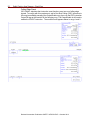
1
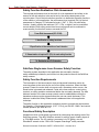
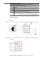
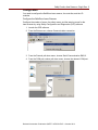
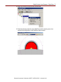
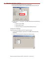
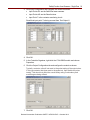
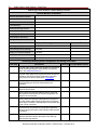
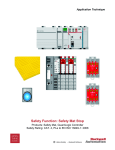
Application Technique
Safety Function: Area Scanners – Single Zone
Products: GuardLogix Controller, SafeZone Laser Scanner
Safety Rating: CAT. 3, PLd to EN ISO 13849-1: 2008
2
Safety Function: Area Scanners – Single Zone
Important User Information
Read this document and the documents listed in the additional resources section about installation,
configuration, and operation of this equipment before you install, configure, operate, or maintain this
product. Users are required to familiarize themselves with installation and wiring instructions in addition
to requirements of all applicable codes, laws, and standards.
Activities including installation, adjustments, putting into service, use, assembly, disassembly, and
maintenance are required to be carried out by suitably trained personnel in accordance with applicable
code of practice.
If this equipment is used in a manner not specified by the manufacturer, the protection provided by the
equipment may be impaired.
In no event will Rockwell Automation, Inc. be responsible or liable for indirect or consequential
damages resulting from the use or application of this equipment.
The examples and diagrams in this manual are included solely for illustrative purposes. Because of the
many variables and requirements associated with any particular installation, Rockwell Automation, Inc.
cannot assume responsibility or liability for actual use based on the examples and diagrams.
No patent liability is assumed by Rockwell Automation, Inc. with respect to use of information, circuits,
equipment, or software described in this manual.
Reproduction of the contents of this manual, in whole or in part, without written permission of Rockwell
Automation, Inc., is prohibited.
Throughout this manual, when necessary, we use notes to make you aware of safety considerations.
WARNING: Identifies information about practices or circumstances that can
cause an explosion in a hazardous environment, which may lead to personal
injury or death, property damage, or economic loss.
ATTENTION: Identifies information about practices or circumstances that can
lead to personal injury or death, property damage, or economic loss. Attentions
help you identify a hazard, avoid a hazard, and recognize the consequence.
IMPORTANT
Identifies information that is critical for successful application and understanding
of the product.
Labels may also be on or inside the equipment to provide specific precautions.
SHOCK HAZARD: Labels may be on or inside the equipment, for example, a
drive or motor, to alert people that dangerous voltage may be present.
BURN HAZARD: Labels may be on or inside the equipment, for example, a drive
or motor, to alert people that surfaces may reach dangerous temperatures.
ARC FLASH HAZARD: Labels may be on or inside the equipment, for example,
a motor control center, to alert people to potential Arc Flash. Arc Flash will cause
severe injury or death. Wear proper Personal Protective Equipment (PPE).
Follow ALL Regulatory requirements for safe work practices and for Personal
Protective Equipment (PPE).
Rockwell Automation Publication SAFETY-AT097A-EN-P – October 2013
Safety Function: Area Scanners – Single Zone 3
General Safety Information
Contact Rockwell Automation to find out more about our safety risk assessment
services.
IMPORTANT
This application example is for advanced users and
assumes that you are trained and experienced in safety
system requirements.
ATTENTION: Perform a risk assessment to make sure all
task and hazard combinations have been identified and
addressed. The risk assessment can require additional
circuitry to reduce the risk to a tolerable level. Safety circuits
must take into consideration safety distance calculations,
which are not part of the scope of this document.
Table of Contents
Important User Information ....................................................................................... 2
General Safety Information ....................................................................................... 3
Introduction ............................................................................................................... 3
Safety Function Realization: Risk Assessment ......................................................... 4
SafeZone Single-zone Laser Scanner Safety Function ............................................. 4
Safety Function Requirements .................................................................................. 4
Functional Safety Description ................................................................................... 4
Bill of Material ........................................................................................................... 5
Setup and Wiring ...................................................................................................... 5
Configuration ............................................................................................................ 9
Programming .......................................................................................................... 20
Calculation of the Performance Level...................................................................... 23
Verification and Validation Plan............................................................................... 25
Additional Resources .............................................................................................. 30
Introduction
This safety function application note explains how to wire, configure, and program a
GuardLogix® controller and POINT Guard I/O™ module to monitor a SafeZone™
laser scanner control. If a demand is placed on the SafeZone laser scanner or a fault
is detected in the monitoring circuit, the GuardLogix controller de-energizes the final
control device, in this case, a redundant pair of 100S contactors.
This example uses a GuardLogix controller and a SafeZone laser scanner. The
SISTEMA calculations shown later in this document must be re-calculated if different
products are used.
Rockwell Automation Publication SAFETY-AT097A-EN-P – October 2013
4
Safety Function: Area Scanners – Single Zone
Safety Function Realization: Risk Assessment
The required performance level is the result of a risk assessment and refers to the
amount of the risk reduction to be carried out by the safety-related parts of the
control system. Part of the risk reduction process is to determine the safety functions
of the machine. In this application, the performance level required (PLr) by the risk
assessment is Category 3, Performance Level d (CAT. 3, PLd), for each safety
function. A safety system that achieves CAT. 3, PLd, or higher, can be considered
control reliable. Each safety product has its own rating and can be combined to
create a safety function that meets or exceeds the PLr.
From: Risk Assessment (ISO 12100)
1. Identification of safety functions
2. Specification of characteristics of each function
3. Determination of required PL (PLr) for each safety function
To: Realization and PL Evaluation
SafeZone Single-zone Laser Scanner Safety Function
The safety system described in this application has one safety function:
safety-related stop initiated by an intrusion into the protective area of the SafeZone
safety scanner.
Safety Function Requirements
The interruption of the laser scanner stops and prevents hazardous motion by
removing power to the motor by the use of two safety contactors. When the laser
scanner is reset, the motor does not resume until a secondary action occurs—the
Reset button is pressed and released. Faults at the laser scanner, control-wiring
terminal, or safety controller are detected before the next safety demand. The safe
distance location of the laser scanner control must be established such that the
hazardous motion must be stopped before the user can reach the hazard. This
distance is called the Safety Distance and is addressed later in this application
technique.
The safety function in this application technique meets or exceeds the requirements
for Category 3, Performance Level d (CAT. 3, PLd), per EN ISO 13849-1 and control
reliable operation per ANSI B11.19.
Functional Safety Description
Hazardous motion is interrupted or prevented by interrupting the sensing zone of the
SafeZone scanner. The 442L SafeZone scanner is wired to a pair of safety inputs of
a 1734-IB8S module. The I/O module is connected, via CIP Safety, over an
EtherNet/IP network to the 1768-L43S Compact GuardLogix® safety controller.
Rockwell Automation Publication SAFETY-AT097A-EN-P – October 2013
Safety Function: Area Scanners – Single Zone 5
The safety code in the safety processor monitors the status of the safety input by
using the pre-certified safety instruction Dual Channel Input Stop (DCS). When all
safety input interlocks are satisfied, no faults are detected, and the Reset button is
pressed and released, a second pre-certified function block called Configurable
Redundant Output (CROUT) controls and monitors feedback for a pair of 100S
redundant contactors. The 100S redundant contactors are wired to a pair of safety
outputs of a 1734-OB8S module.
In summary, when the SafeZone scanner is blocked, the contactors drop out. When
the SafeZone scanner is unblocked, and the Reset button is pressed and released,
the contactors are energized.
Bill of Material
This application uses these products.
Cat. No.
Description
Quantity
1585J-M4TBJM-2
1585 Ethernet cables, 4 conductors, RJ45, straight male,
standard, RJ45, straight male, teal robotic TPE, UL CMB, 2
CMX, CUL, CMG, standard TIA 568-B
1783-US05T
Stratix 2000™ switch, unmanaged, 5 copper ports
1
1768-ENBT
EtherNet/IP bridge module
1
1768-L43S
CompactLogix™ L43 safety processor, 2.0 Mb standard
memory, 0.5 Mb safety memory
1
1768-PA3
Power supply 120/240V AC input 3.5 A @ 24V DC
1
1769-ECR
Right end cap/terminator
1
1734-AENT
EtherNet/IP twisted-pair media I/O adapter
1
1734-IB8S
POINT Guard I/O safety module, 8-point input module
(compatible with terminal bases with 8 terminations)
1
1734-OB8S
POINT Guard I/O safety module, 8-safety sourcing
output module (compatible with terminal bases with 8
terminations)
1
1734-TBS
Module bases with removable IEC spring terminals
(quantity 10)
4
1794-PS13
85…264V AC to 24V DC 1.3 A power supply
1
442L-SFZNSZ
SafeZone single-zone scan head and I/O module
1
442L-CSFZNMZ-10
10M pre-wired 13-conductor memory module
1
442L-ACRS232
2M RS-232 configuration cable
1
100S-C09ZJ23C
MCS 100S-C safety contactor, 9 A, 24V DC
2
800FM-G611MX10
800F push button - metal, guarded, blue, R, metal latch
mount, 1 N.O. contact, 0 N.C. contacts, standard pack
1
Setup and Wiring
For detailed information on installing and wiring, refer to the publications listed in the
Additional Resources on the back cover.
System Overview
The 1734-IB8S safety input module monitors the input from the SafeZone laser
scanner control. The SafeZone laser scanner control provides two PNP outputs that
are turned off when an object interrupts its field of view.
Rockwell Automation Publication SAFETY-AT097A-EN-P – October 2013
6
Safety Function: Area Scanners – Single Zone
If intrusion in the SafeZone area is detected, the final control devices, a pair of 100S
safety contractors (K1 and K2) are de-energized. The contactors are controlled by a
1734-OBS safety output module. These are wired in a redundant configuration and
are tested on startup for faults. The start-up test is accomplished by using a
Configurable Redundant Output (CROUT) instruction to monitor the feedback circuit
into input 7 (I7) before the contactors are energized. These de-energized contactors
remove power to the motor. The motor coasts to a stop (Stop Category 0). When the
SafeZone laser scanner control resumes its normal state, these contactors are not
energized until the system is reset by a momentary push button (PB1).
The system is to be designed such that no single fault results in the safety system
failing to perform its safety function. A single fault is detected before the next
demand on the safety system. The system cannot be reset until the fault is corrected.
The Reset buttons and the contactor feedback circuit are all wired to the 1734-IB8S
module. The Reset buttons can also be wired to a standard input module.
Installation
A SafeZone laser scanner provides no physical barrier between a person and the
hazardous motion. The scanner must be installed at a sufficient distance from the
hazardous motion to make sure that anyone entering into the configured sensing
zone cannot reach the hazard before it has stopped. This distance is referred to as
the Safety Distance.
The Safety Distance (S) requirement varies from installation-to-installation and,
therefore, must be calculated for each specific application. This application note uses
the formula from EN ISO 13855.
The safety distance (S) depends on:
•
•
Approach speed of the body or parts of the body
Stopping/run-down time of the machine or system
IMPORTANT
The stopping/run-down time is shown in the machine
documentation or must be determined by taking a
measurement.
•
•
Response time of the SafeZone safety laser scanner
Supplements for general measurement errors and any measurement errors
related to reflection
Supplement for prevention of reaching over
Height of the scan plane
•
Time for switching between the monitoring cases
•
•
ATTENTION: Avoid mounting retro-reflectors at a distance
of less than 1 m (3.28 ft) from the boundary of the protective
safety field.
With retro-reflectors positioned at a distance of less than
1 m (3.28 ft) from the boundary of the protective safety field
a supplement, ZR, of 200 mm (7.87 in.) must be added to
the protective safety field.
Rockwell Automation Publication SAFETY-AT097A-EN-P – October 2013
Safety Function: Area Scanners – Single Zone 7
Formula: S = (K x (TM + TS)) + ZG + ZR + C
Symbol
Definition
S
Minimum distance, in millimeters (mm)
K
Parameter, in millimeters per second (mm/s), derived from data on approach
speeds of the body or parts of the body
TM
Stopping/run-down time of the machine or system
TS
Response time of the SafeZone multizone safety laser scanner combined with
the downstream controller
ZG
General safety supplement = 100 mm
ZR
Supplement for measurement error related to reflection
There are no reflective surfaces that could affect the safety laser scanner;
therefore, ZR = 0.
C
Supplement for prevention of reaching over
In this example, the stopping time (T) is a summation of the following.
Input Values
SafeZone laser scanner control delay time: 60 ms (from product documentation)
1734-IB8S delay = 16 ms (from product documentation)
1
Input Module Connection delay
2
Safety Controller delay
•
Safety Task Watchdog
•
Safety Task Period
3
Output Module Connection Delay
1734-OB8S delay = 6 ms (from product documentation)
Contactor response time = 15 ms (from product documentation)
Actual Machine stop time = Assume 900 ms for this example
1
The Input Module connection delay defaults to 4 x requested packet interval (RPI).
If we assume a RPI of 10 ms, the maximum delay = 40 ms
2
The safety controller delay is a combination of the safety task period plus the safety task
watchdog. The watchdog accounts for the possibility that the safety code runs right up to,
but does not trip the watchdog. The safety task period accounts for the possibility that the
asynchronous scan just ended when the input changed state. For this example, the
following assumptions were made:
Safety Task Period = 10 ms
Safety Task Watchdog = 5 ms
Therefore, the TM + TS in this example is 1029 ms.
3
The Output Module connection delay defaults to 3 x RPI.
If we assume a RPI of 10 ms, the maximum delay = 30 ms
The worst case reaction time can be calculated by assuming there is only a single fault in the
control system. This means that only the higher of the two connection delay values shown
above, needs to be included in the time calculation. For this example, 40 ms is used, and the
30 ms is excluded. To account for multiple faults occurring at the same time, use both values
in the calculation.
Rockwell Automation Publication SAFETY-AT097A-EN-P – October 2013
8
Safety Function: Area Scanners – Single Zone
Calculation using the formula: S = (K x (TM + TS)) + ZG + ZR + C
In this application technique, these are the values.
K
1600 mm/s
TM + TS
1029 ms
ZG + ZR
100 mm
C
850 mm (with reference to the Multi-beam formula)
S
1600 x 1.029 + 100 + 850 = 2596.4
Conclusion: The SafeZone laser scanner must not be mounted closer than
2596.4 mm from the hazardous motion being guarded against.
Electrical Schematic
Input Circuit
Circuit
Reset
Fault
Reset
Brown
Pink
Gray
Blue
Output Circuit
1734-OB8S
Where K1 and K2 are safety contactors.
Rockwell Automation Publication SAFETY-AT097A-EN-P – October 2013
Safety Function: Area Scanners – Single Zone 9
Configuration
You need to configure the SafeZone laser scanner, the controller, and the I/O
modules.
Configure the SafeZone Laser Scanner
Configure the number of zones, the safety zones, and the warning zones for the
laser scanner by using Safety Configuration and Diagnostics (SCD) software.
1. Launch the SCD software.
2. From the Extras menu, choose Communication connection.
3. From the Protocol pull-down menu, choose Serial Communication RK512.
4. From the COM port number pull-down menu, choose the relevant COM port.
Rockwell Automation Publication SAFETY-AT097A-EN-P – October 2013
10
Safety Function: Area Scanners – Single Zone
5. Create a new project, and then right-click Project and choose Add device.
6. From the Device classes pull-down menu, choose SafeZone Laser Scanner.
7. Choose the model number for the SafeZone laser scanner.
Rockwell Automation Publication SAFETY-AT097A-EN-P – October 2013
Safety Function: Area Scanners – Single Zone 11
8. Right-click SafeZone systems > Configuration draft > Edit.
9. Type the Application name and the Scanner name 1 and then click Continue.
10. Under Application, click Stationary and then click Continue.
Rockwell Automation Publication SAFETY-AT097A-EN-P – October 2013
12
Safety Function: Area Scanners – Single Zone
11. Under Resolution, click 150 mm (body detection) and then click Continue.
12. Verify that the External device monitoring active is cleared and then click
Continue.
13. Under Restart, click Without restart interlock and then click Continue.
Rockwell Automation Publication SAFETY-AT097A-EN-P – October 2013
Safety Function: Area Scanners – Single Zone 13
14. Right-click SafeZone and choose Edit field sets.
15. Draw the relevant protective area (SafeZone) and the warning area, then
transmit the configuration to the SafeZone laser scanner.
Rockwell Automation Publication SAFETY-AT097A-EN-P – October 2013
14
Safety Function: Area Scanners – Single Zone
Configure the Controller and Add I/O Modules
The Compact GuardLogix controller is configured by using RSLogix™ 5000
software, version 17 or later. You must create a new project and add the I/O
modules. Then, configure the I/O modules for the correct input and output types. A
detailed description of each step is beyond the scope of this document. Knowledge
of the RSLogix programming environment is assumed.
1. In RSLogix 5000 software, create a new project.
2. Choose a controller.
a. From the Type pull-down menu, choose 1768-L43S CompactLogix 5343S
Safety Controller.
b. From the Revision pull-down menu, choose the appropriate revision for
the controller.
c. In the Name box, type an appropriate name for the controller.
d. Click OK.
3. In the Controller Organizer, right-click 1768 Bus and choose New Module.
Rockwell Automation Publication SAFETY-AT097A-EN-P – October 2013
Safety Function: Area Scanners – Single Zone 15
4. Choose the 1768-ENBT module and click OK.
5. Name the module, type its IP address, and click OK.
For this application example, we used 192.168.1.8; however, your IP address
can be different.
6. In the Controller Organizer, right-click the 1768-ENBT module and choose
New Module.
Rockwell Automation Publication SAFETY-AT097A-EN-P – October 2013
16
Safety Function: Area Scanners – Single Zone
7. Select the 1734-AENT adapter and click OK.
8. Name the module, type its IP address, and click OK.
For this application example, we used 192.168.1.11; however, your IP
address can be different.
9. Click Change.
The Module Definition dialog box appears.
Rockwell Automation Publication SAFETY-AT097A-EN-P – October 2013
Safety Function: Area Scanners – Single Zone 17
10. From the Chassis Size pull-down menu, choose 3 and click OK.
Chassis size is the number of modules that is inserted in the chassis. The
1734-AENT adapter is considered to be in slot 0; therefore, for one input and
one output module, the chassis size is 3.
11. In the Controller Organizer, right-click the 1734-AENT adapter and choose
New Module.
12. Expand Safety, select the 1734-IB8S module, and click OK.
13. In the New Module dialog box, name the device IB8S, then click Change.
The Module Definition dialog box appears.
Rockwell Automation Publication SAFETY-AT097A-EN-P – October 2013
18
Safety Function: Area Scanners – Single Zone
14. From the Output Data pull-down menu, choose None.
15. Verify that the Input Status is set to Combined Status-Power, and click OK.
16. Repeat steps 10…14 to add the 1734-OB8S safety output module with these
exceptions:
•
Name the module OB8S
•
Set the module to slot 2
•
Set the Input Status to Combined Status-Read back-Power
Configure the I/O Modules
Follow these steps to configure the POINT Guard I/O modules.
1. In the Controller Organizer, right-click the 1734-IB8S module and choose
Properties.
2. Click the Test Output tab and configure the module as shown.
Rockwell Automation Publication SAFETY-AT097A-EN-P – October 2013
Safety Function: Area Scanners – Single Zone 19
3. Click Input Configuration and configure the module as shown:
•
Input Points 0/1 are the SafeZone laser scanners.
•
Input Points 4/5 are the Reset buttons.
•
Input Point 7 is the contactor monitoring circuit.
Recall that input point 7 is being sourced from Test Output 2.
4. Click OK.
5. In the Controller Organizer, right-click the 1734-OB8S module and choose
Properties.
6. Click the Output Configuration tab and configure the module as shown.
Typically, contactor coils will not react to the pulse testing of the output wires.
If using a contactor that does react to the pulse test, then disable the pulse
testing. This should not affect the overall safety rating if redundancy and
monitoring are being utilized.
7. Click OK.
Rockwell Automation Publication SAFETY-AT097A-EN-P – October 2013
20
Safety Function: Area Scanners – Single Zone
Programming
The Dual Channel Input Stop (DCS) instruction monitors dual-input safety devices
whose main function is to stop a machine safely, for example, an E-stop, light
curtain, or safety gate. In this example, it is being used to monitor a SafeZone laser
scanner.
The DCS instruction monitors dual-input channels for consistency (Equivalent-Active
High) and detects and traps faults when the inconsistency is detected for longer than
the configured Discrepancy Time (ms).
The automatic restart type allows the DCS output (O1) to reset automatically after a
demand. The manual action typically required for safety is provided in rung 1 to reset
the safety output enable.
Input Status typically represents the channel status of the two input channels. In this
example, the Combined Input Status bit goes low (0) if any of the eight input
channels has a fault.
In this example, the DCS reset acts as a fault reset. Even when configured for
automatic restart, a reset is required to recover from a fault.
The output (O1) of the DCS is used as a safety interlock in the seal-in rung to drive
the output enable tag. If the DCS output drops out, so does the output enable, and it
remains off until a manual reset action is carried out.
The Configurable Redundant Output (CROUT) instruction controls and monitors
redundant outputs. Essentially, this instruction verifies that feedback follows the
safety outputs appropriately. For the negative feedback used in this example, if the
outputs are high (1), the feedback is low (0) and vice versa. In this example, the
feedback has 500 ms to change to the proper state. Because only a single feedback
circuit is being used, the feedback tag is used for both Feedback 1 and 2.
The two output tags from the CROUT instruction are used to drive the contactor
outputs on the 1734-OB8S module.
Rockwell Automation Publication SAFETY-AT097A-EN-P – October 2013
Safety Function: Area Scanners – Single Zone 21
Rockwell Automation Publication SAFETY-AT097A-EN-P – October 2013
22
Safety Function: Area Scanners – Single Zone
Falling Edge Reset
ISO 13849-1 stipulates that instruction reset functions must occur on falling edge
signals. To comply with this requirement, add a One Shot Falling (OSF) instruction to
the rung immediately preceding the OutputEnable rung, then use the OSF instruction
Output Bit tag as the reset bit for the following rung. The OutputEnable is still used to
enable the CROUT instruction. The modified code appears below in rungs 1 and 2.
Rockwell Automation Publication SAFETY-AT097A-EN-P – October 2013
Safety Function: Area Scanners – Single Zone 23
Calculation of the Performance Level
When properly implemented, the SafeZone laser scanner safety function can
achieve a safety rating of Category 3, Performance Level d (CAT. 3, PLd), according
to EN ISO 13849-1: 2008, as calculated using the SISTEMA Software PL Calculation
Tool.
The individual subsystem values are shown below.
The overall Safety function value is shown below.
The laser scanner safety function can be modeled as shown in the following safety
block diagram.
K1
100S
442LSFZNSZ
1734-IB8S
1768-L43S
1734-OB8S
K2
100S
Subsystem 1
Subsystem 2
Subsystem 3
Subsystem 4
Subsystem 5
Calculations are based on one operation of the scanner per hour; therefore, 8760
operations of the contactor per year.
The measures against Common Cause Failure (CCF) are quantified by using the
scoring process outlined in Annex F of EN ISO 13849-1. For the purposes of the
Performance Level calculation, the required score of 65, needed to fulfill the CCF
requirement, is considered to be met.
Rockwell Automation Publication SAFETY-AT097A-EN-P – October 2013
24
Safety Function: Area Scanners – Single Zone
The complete CCF scoring process must be performed when implementing this
example.
Because these are electro-mechanical devices, the safety contactors data includes
the following:
•
Mean Time to Failure, dangerous (MTTFd)
•
Diagnostic Coverage (DCavg)
•
Common Cause Failure (CCF)
Rockwell Automation Publication SAFETY-AT097A-EN-P – October 2013
Safety Function: Area Scanners – Single Zone 25
Electro-mechanical devices’ functional safety evaluations include the following:
•
How frequently they are operated
•
Whether they are effectively monitored for faults
•
Whether they are properly specified and installed
SISTEMA software calculates the MTTFd by using B10d data provided for the
contactors along with the estimated frequency of use, entered during the creation of
the SISTEMA project.
The DCavg (99%) for the contactors is selected from the Output Device table of
EN ISO 13849-1 Annex E, Direct Monitoring.
The CCF value is generated by using the scoring process outlined in Annex F of
EN ISO 13849-1. The complete CCF scoring process must be performed when
actually implementing an application. A minimum score of 65 must be achieved.
Verification and Validation Plan
Verification and validation play important roles in the avoidance of faults throughout
the safety system design and development process. EN ISO 13849-2 sets the
requirements for verification and validation. The standard calls for a documented
plan to confirm all of the safety functional requirements have been met.
Verification is an analysis of the resulting safety control system. The Performance
Level (PL) of the safety control system is calculated to confirm that the system meets
the required Performance Level (PLr) specified. The SISTEMA software is typically
used to perform the calculations and assist with satisfying the requirements of
EN ISO 13849-1.
Validation is a functional test of the safety control system to demonstrate that the
system meets the specified requirements of the safety function. The safety control
system is tested to confirm that all of the safety-related outputs respond
appropriately to their corresponding safety-related inputs. The functional test
includes normal operating conditions in addition to potential fault injection of failure
modes. A checklist is typically used to document the validation of the safety control
system.
Validation of software development is the process in which similar methodologies
and techniques that are used in hardware development are deployed. Faults created
through poor software development processes and procedures are systemic in
nature rather than faults associated with hardware, which are considered as random.
Prior to validating the GuardLogix Safety System, it is necessary to confirm that the
safety system and safety application program have been designed in accordance
with the GuardLogix System Safety Reference Manuals, publication 1756-RM093
(GuardLogix 5560 and Compact GuardLogix controllers) and 1756-RM099
(GuardLogix 5570 controllers), and the GuardLogix Application Instruction Safety
Reference Manual, publication (1756-RM095).
Rockwell Automation Publication SAFETY-AT097A-EN-P – October 2013
26
Safety Function: Area Scanners – Single Zone
GuardLogix Laser Scanner Control Safety Function
General Machine Information
Machine Name/Model Number
Customer Name
Test Date
Tester Name(s)
Schematic Drawing Number
Controller Name
Safety Signature ID
Safety Network Number(s)
RSLogix 5000 Software Version
GuardLogix Modules
Safety Control System Modules
GuardLogix Safety Controller
1768-L43S
CompactLogix Ethernet Bridge
1768-ENBT
POINT I/O™ Ethernet Adapter
1734-AENT
POINT I/O Input Modules
1734-IB8S
POINT I/O Output Modules
1734-OB8S
Firmware Revision
GuardLogix Safety System Configuration and Wiring Verification
Test Step
Verification
Pass/Fail Changes/Modifications
Verify that safety system has been designed in accordance
with the GuardLogix System Safety Reference Manuals
listed in the Additional Resources.
Verify that safety application program has been designed in
accordance with the GuardLogix Application Instruction
Safety Reference Manual, publication 1756-RM095.
Visually inspect the safety system network and I/O modules
to verify that they are wired as documented in the
schematics.
Visually inspect the SafeZone laser scanner to verify that it
is wired as documented.
Visually inspect the RSLogix 5000 program to verify that
safety systems network and I/O module configuration are
configured as documented.
Visually inspect the RSLogix 5000 application program to
verify that suitable safety-certified instructions are utilized
and the logic is readable, understandable, and testable with
the aid of clear comments.
All input devices are qualified by cycling their respective
actuators. Monitor the status in the RSLogix 5000 controller
tags window.
All of the output devices are qualified by cycling their
respective actuators. Monitor the status in the RSLogix
5000 controller tags window.
Rockwell Automation Publication SAFETY-AT097A-EN-P – October 2013
Safety Function: Area Scanners – Single Zone 27
GuardLogix Laser Scanner Control Safety Function (continued)
Normal Operation Verification - The GuardLogix safety system properly responds to all normal
Start, Stop, Scanner Input, and Reset commands.
Test Step
Verification
Pass/Fail Changes/Modifications
Initiate a Start command. Both contactors energize for a
normal machine Run condition. Verify proper machine
status indication and RSLogix 5000 safety application
program indication.
Initiate a Stop command. Both contactors de-energize for a
normal machine Stop condition. Verify proper machine
status indication and RSLogix 5000 safety application
program indication.
While the system is running, interrupt the SafeZone laser
scanner. Both contactors de-energize and open for a normal
safe condition. Verify proper machine status indication and
RSLogix 5000 safety application program indication.
While the system is stopped, interrupt SafeZone laser
scanner and initiate a Start command. Both contactors
remain de-energized and open for a normal safe condition.
Verify proper machine status indication and RSLogix 5000
safety application program indication.
Initiate a Reset command. Both contactors remain
de-energized. Verify proper machine status indication and
RSLogix 5000 safety application program indication.
Rockwell Automation Publication SAFETY-AT097A-EN-P – October 2013
28
Safety Function: Area Scanners – Single Zone
GuardLogix Laser Scanner Control Safety Function (continued)
Abnormal Operation Validation - The safety system properly responds to all foreseeable faults
with corresponding diagnostics.
SafeZone Laser Scanner Control Safety Input tests
Test Step
Validation
Pass/Fail Changes/Modifications
While the system is running, remove the channel 1 wire
from the safety I/O module. Both contactors de-energize.
Verify proper machine status indication and RSLogix 5000
safety application program indication. Verify that the system
is unable to reset and restart with fault. Restore channel 1
and repeat for channel 2.
While the system is running, short the channel 1 of the
safety I/O module to 24V DC. Both contactors de-energize.
Verify proper machine status indication and RSLogix 5000
safety application program indication. Repeat for channel 2.
Verify that the system is unable to reset and restart with
fault. Restore channel 1 and repeat for channel 2.
While the system is running, short the channel 1 of the
safety I/O module to 0V DC. Both contactors de-energize.
Verify proper machine status indication and RSLogix 5000
safety application program indication. Repeat for channel 2.
Verify that the system is unable to reset and restart with
fault. Restore channel 1 and repeat for channel 2.
While the system is running, short channels 1 and 2 of the
safety I/O module. Both contactors de-energize. Verify
proper machine status indication and RSLogix 5000 safety
application program indication. Verify that the system is
unable to reset and restart with fault. Restore channel 1 and
channel 2 wiring.
GuardLogix Control and Network Tests
Test Step
Verification and Validation
Pass/Fail Changes/Modifications
While the system is running, remove the Ethernet network
connection between the safety I/O module and the
controller. All contactors de-energize. Verify proper machine
status indication and I/O connection status in the RSLogix
5000 safety application program.
Restore the Safety I/O module network connection and
allow time to re-establish communication. Verify the value of
the connection status bit in the RSLogix 5000 safety
application program.
While the system is running, switch the controller out of Run
mode. All contactors de-energize. Return the keyswitch
back to Run mode. All contactors remain de-energized.
Verify proper machine status indication and RSLogix 5000
safety application program indication.
Rockwell Automation Publication SAFETY-AT097A-EN-P – October 2013
Safety Function: Area Scanners – Single Zone 29
GuardLogix Laser Scanner Control Safety Function (continued)
Safety Contactor Output Tests
Test Step
Verification and Validation
Pass/Fail Changes/Modifications
Initiate a Start command. Both contactors energize for a
normal machine run condition. Verify proper machine status
indication and RSLogix 5000 safety application program
indication.
While the system is running, remove the contactor feedback
from the safety I/O module. All contactors remain energized.
Initiate a Stop command and attempt a Reset command.
The system does not restart or reset. Verify proper machine
status indication and RSLogix 5000 safety application
program indication.
While the system is running, short the contactor feedback to
the safety I/O module. All contactors remain energized.
Initiate a Stop command and attempt a Reset command.
The system does not restart or reset. Verify proper machine
status indication and RSLogix 5000 safety application
program indication.
Rockwell Automation Publication SAFETY-AT097A-EN-P – October 2013
30
Safety Function: Area Scanners – Single Zone
Additional Resources
Refer to these publications for more information about related products from
Rockwell Automation.
Resource
Description
Compact GuardLogix Controllers User
Manual, publication 1768-UM002
Provides information on configuring, operating,
and maintaining Compact GuardLogix controllers.
POINT Guard I/O Safety Modules
Installation and User Manual,
publication 1734-UM013
GuardLogix Control Systems Safety
Reference Manual, publication
1756-RM093
GuardLogix Safety Application
Instruction Set Reference Manual,
publication 1756-RM095
Provides information on installing, configuring, and
operating POINT Guard I/O modules.
GuardLogix 5570 Controller Systems
Safety Reference Manual, publication
1756-RM099
Contains detailed requirements for achieving and
maintaining safety ratings with the GuardLogix
5570 controller system.
Safety Accelerator Toolkit for
GuardLogix System Quick Start Guide,
publication IASIMP-QS005
SafeZone Singlezone & Multizone
Safety Laser Scanner User Manual,
publication 10000073050, Ver 01
Safety Product Catalog, publication
S117-CA001
Provides a step-by-step guide to using the design,
programming, and diagnostic tolls in the Safety
Accelerator Toolkit.
Provides information on installing, configuring, and
operating a SafeZone Safety Laser Scanner.
Contains detailed requirements for achieving and
maintaining safety ratings with the GuardLogix
and Compact GuardLogix controller systems.
Provides detailed information on the GuardLogix
Safety Application Instruction Set.
Data and guidance concerning safety principals,
standards component data and application
examples.
You can view or download publications at
http://www.rockwellautomation.com/literature. To order paper copies of technical
documentation, contact your local Allen-Bradley distributor or Rockwell Automation
sales representative.
For more information on
Safety Function Capabilities, visit:
discover.rockwellautomation.com/safety
Rockwell Automation, Allen-Bradley, Rockwell Software, GuardLogix, RSLogix, Stratix 2000, Compact GuardLogix, CompactLogix, POINT Guard I/O, POINT I/O, SafeZone,
and LISTEN.THINK.SOLVE. are trademarks of Rockwell Automation, Inc. Trademarks not belonging to Rockwell Automation are property of their respective
companies.
Publication SAFETY-AT097A-EN-P – October 2013
Copyright © 2013 Rockwell Automation, Inc. All rights reserved. Printed in U.S.A.