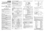
1
For QnA Ethernet Interface Module User's Manual (Hardware) AJ71QE71N-T, A1SJ71QE71N-T AJ71QE71N-B5, A1SJ71QE71N-B5 AJ71QE71N-B2, A1SJ71QE71N-B2 Thank you for buying the Mitsubishi general-purpose programmable logic controller MELSEC-QnA Series Prior to use, please read both this manual and detailed manual thoroughly and familiarize yourself with the product. MODEL QE71N-U-HW MODEL 13JT54 CODE IB (NA)-0800182-B (0305) MEE 2002 MITSUBISHI ELECTRIC CORPORATION z SAFETY PRECAUTIONS z (Always read before starting use) When using Mitsubishi equipment, thoroughly read this manual and the associated manuals introduced in the manual. Also pay careful attention to safety and handle the module properly. These precautions apply only to the installation of Mitsubishi equipment and the wiring with the external device. Refer to the user's manual of the CPU module to be used for a description of the PLC system safety precautions. These SAFETY PRECAUTIONS classify the safety precautions into two categories: "DANGER" and "CAUTION". DANGER Procedures which may lead to a dangerous condition and cause death or serious injury if not carried out properly. CAUTION Procedures which may lead to a dangerous condition and cause superficial to medium injury, or physical damage only, if not carried out properly. CAUTION may also be linked Depending on circumstances, procedures indicated by to serious results. In any case, it is important to follow the directions for usage. Store this manual in a safe place so that you can take it out and read it whenever necessary. Always forward it to the end user. A-1 [DESIGN PRECAUTIONS] CAUTION z When laying the control wire or communication cable, do not bundle with or place near main circuit or power line. Keep them at least 100 mm (3.94 in.) away from such cables. Noise may cause erroneous operation. [INSTALLATION PRECAUTIONS] CAUTION z Use the PLC in the environment given in the general specifications section of the user's manual to be used. Using the PLC outside the range of the general specifications may result in electric shock, fire, or erroneous operation or may damage or degrade the product. z Install so that the tabs at the bottom of the module fit securely into the base unit mounting holes. (The Q2AS series module shall be fastened by screws in the base unit at the specified torque.) Not installing the module correctly could result in erroneous operation, damage, or pieces of the product falling. Tighten the screw within the range of specified torque. z If the screws are loose, it may result in fallout, short circuits or malfunction. Tightening the screws to far may cause damage to the screw and/or the module, resulting in fallout, short circuits or malfunction. z Make sure to switch all phases of the external power supply off before mounting or removing the module. If you do not switch off the external power supply, it will cause electric shock or damage to the product. z Do not touch the electronic parts or the module conducting area directly. It may cause erroneous operation or failure. A-2 [WIRING PRECAUTIONS] CAUTION z Perform correct pressure-displacement, crimp-contact or soldering for external wire connections using the tools specified by the manufactures. Incorrect connection may cause short circuits, fire or malfunction. z Attach connector to the module securely. z Be sure to fix communication cables or power supply cables leading from the module by placing them in the duct or clamping them. Cables not placed in the duct or without clamping may hang or shift, alllowing them to be accidentally pulled, which may cause a module malfunction and cable damage. z Tighten the screw within the range of specified torque. If the screws are loose, it may result in short circuits or malfunction. Tightening the screws to far may cause damage to the screw and/or the module, resulting in fallout, short circuits or malfunction. z Do not grab on the cable when removing the communication cable connected to the module. When removing the cable with a connector, hold the connector on the side that is connected to the module. When removing the cable connected to the terminal block, first loosen the screws on the part that is connected to the terminal block. Pulling the cable that is still connected to the module may cause a malfunction or damage to the module or cable. z Solder coaxial cable connectors properly. Insufficient soldering may cause malfunction. z Be sure that cuttings, wire chips, or other foreign matter do not enter the module. Foreign matter may start a fire or cause an accident or erroneous operation. A-3 Revisions The manual number is given on the bottom left of the back cover. Print Date Mar., 2002 May, 2003 Manual Number IB (NA)-0800182-A IB (NA)-0800182-B Revision First printing Additional model AJ71QE71N-T, A1SJ71QE71N-T, AJ71QE71N-B5, A1SJ71QE71N-B5 Deleted model AJ71QE71N-B5T, A1SJ71QE71N-B5T This manual confers no industrial property rights or any rights of any other kind, nor does it confer any patent licenses. Mitsubishi Electric Corporation cannot be held responsible for any problems involving industrial property rights which may occur as a result of using the contents noted in this manual. 2002 MITSUBISHI ELECTRIC CORPORATION A-4 CONTENTS 1. 2. 3. 4. Overview ............................................................................................................................ 1 Performance Specifications ............................................................................................... 2 Settings and Names of Each Part ...................................................................................... 5 Loading and Installation ..................................................................................................... 9 4.1 Handling Precautions................................................................................................... 9 4.2 Installation Environment............................................................................................... 9 5. Connection to a Network.................................................................................................. 10 5.1 Connecting to the 10BASE-T (AJ71QE71N-T, A1SJ71QE71N-T) ............................ 11 5.2 Connecting to the 10BASE5 (AJ71QE71N-B5, A1SJ71QE71N-B5) ......................... 11 5.3 Connecting to the 10BASE2 (AJ71QE71N-B2, A1SJ71QE71N-B2) ......................... 11 6. External Dimensions ........................................................................................................ 12 A-5 About the Manuals The following product are available for this equipment. Refer to the table given below to choose suitable manuals. Detailed Manual Manual name For QnA Ethernet Interface Module User's Manual Manual No. (Model code) SH-080146 (13JR33) Related Manual Manual name For A Ethernet Interface Module User's Manual Manual No. (Model code) SH-080192 (13JR45) Conformation to the EMC Directive and Low Voltage Instruction For details on making Mitsubishi PLC conform to the EMC directive and low voltage instruction when installing it in your product, please refer to Chapter 3, "EMC Directive and Low Voltage Instruction" of the User's Manual (Hardware) for the CPU module to use. The CE logo is printed on the rating plate on the main body of the PLC that conforms to the EMC directive and low voltage instruction. For information about conforming this product to the EMC directive and low voltage instruction, please refer to Chapter 3 "EMC Directive and low Voltage Instruction," section "3.1.3. Cable" of the User's Manual (Hardware) for the CPU module to use. A-6 1. Overview This manual explains how to install the following Ethernet interface modules (abbreviated as QE71 hereafter) for QnA series PLC CPU and how to wire them with external devices. After unpacking QE71, verify that the following parts are contained. Model name Product name No. of items AJ71QE71N-T AJ71QE71N-T type Ethernet Interface Module 1 AJ71QE71N-B5 AJ71QE71N-B5 type Ethernet Interface Module 1 AJ71QE71N-B2 type Ethernet Interface Module 1 AJ71QE71N-B2 F type Connector (A6RCON-F) 1 A1SJ71QE71N-T A1SJ71QE71N-T type Ethernet Interface Module 1 A1SJ71QE71N-B5 A1SJ71QE71N-B5 type Ethernet Interface Module 1 A1SJ71QE71N-B2 type Ethernet Interface Module 1 A1SJ71QE71N-B2 F type Connector (A6RCON-F) 1 1 2. Performance Specifications The performance specifications of QE71 is shown below. See CPU module user's manual to be used for QE71 general specifications. Specifications AJ71QE71N-T A1SJ71QE71N-T 10BASE-T Item Data transmission speed Communication mode Transmission method Maximum distance Transmission between nodes specifications Maximum segment length Maximum number of nodes/connection Minimum node interval Number of allowable Transmission simultaneously open data storage connections Fixed buffer memory Random access buffer Number of remote nodes that can be communicated in a single initial processing EEPROM write frequency Number of occupied I/O points 5 V DC internal current consumption Connector Connection cable 12 V DC external power supply capacity (for transceiver) External dimensions Weight 10 Mbps Half-duplex Base band — 100 m (328.08 ft.) ( 1) Cascade connection is a maximum 4 stages — 8 connections (Connections usable by the sequence program) 1 k word × 8 6 k word × 1 No restrictions Maximum of 10,000 times in the same area 32 points /1 slot (I/O assignments : special 32 points) AJ71QE71N-T : 0.40A A1SJ71QE71N-T : 0.40A Modular jack (RJ45) Un-shield twisted pair cable (UTP category 3 (4, 5)) — AJ71QE71N-T : 250 (9.84) (H) × 37.5 (1.48) (W) × 106 (4.17) (D) [mm (in.)] A1SJ71QE71N-T : 130 (5.12) (H) × 34.5 (1.36) (W) × 94 (3.70) (D) [mm (in.)] y All do not include the protruded section on the front surface. AJ71QE71N-T : 0.30 kg (0.66Ib.) A1SJ71QE71N-T : 0.17 kg (0.37Ib.) 2 Item Data transmission speed Communication mode Transmission method Maximum distance Transmission between nodes specifications Maximum segment length Maximum number of nodes/connection Minimum node interval Number of allowable Transmission simultaneously open data storage connections Fixed buffer memory Random access buffer Number of remote nodes that can be communicated in a single initial processing EEPROM write frequency Number of occupied I/O points 5 V DC internal current consumption Connector Connection cable Specifications AJ71QE71N-B5 AJ71QE71N-B2 A1SJ71QE71N-B5 A1SJ71QE71N-B2 10BASE5 10BASE2 10 Mbps Half-duplex Base band 2500 m (8202.10 ft.) 925 m (3034.77 ft.) 500 m (1640.42 ft.) 185 m (606.96 ft.) 100 nodes per segment 30 nodes per segment 2.5m (8.20 ft.) 0.5m (1.64 ft.) 8 connections (Connections usable by the sequence program) 1 k word × 8 6 k word × 1 No restrictions Maximum of 10,000 times in the same area 32 points /1 slot (I/O assignments : special 32 points) AJ71QE71N-B5 : 0.40A AJ71QE71N-B2 : 0.56A A1SJ71QE71N-B5 : 0.40A A1SJ71QE71N-B2 : 0.53A D-sub connector BCN connector (Male 15-pin) AUI cable Coaxial Cable (Twisted pair cable) (RG58A/U, RG58C/U) 12 V DC external power supply capacity (for transceiver) External dimensions Weight ( 2) — AJ71QE71N-B5, AJ71QE71N-B2 : 250 (9.84) (H) × 37.5 (1.48) (W) × 106 (4.17) (D) [mm (in.)] A1SJ71QE71N-B5, A1SJ71QE71N-B2 : 130 (5.12) (H) × 34.5 (1.36) (W) × 94 (3.70) (D) [mm (in.)] y All do not include the protruded section on the front surface. AJ71QE71N-B5 AJ71QE71N-B2 : 0.33kg (0.73Ib.) : 0.35kg (0.77Ib.) A1SJ71QE71N-B5 A1SJ71QE71N-B2 : 0.19kg (0.42Ib.) : 0.20kg (0.44Ib.) 1 Length between hub and node. 2 It is required to use the one that satisfies the specifications of the transceiver and the AUI cable. Also, for the AJ71QE71N-B5, the voltage drop (Max. 0.8V) must be taken into account. 3 Notes (1) Each item in the transmission specifications gives supplementary explanation. •When connected by 10BASE2, 10BASE5 Segment length Node Transceiver Terminator Node Repeater Node Maximum distance between nodes Node Node • When connected by 10BASE-T Hub Cascade connection is a maximum of 4 stages Maximum 100 m (328.08 ft.) Maximum 100 m (328.08 ft.) QE71 (2) Hardware specifications for QE71 are based on IEEE802.3. 4 Segment length Segment length Repeater 3. Settings and Names of Each Part AJ71QE71N-T AJ71QE71N-B5 AJ71QE71N-B5 AJ71QE71N-T BUF1 BUF2 BUF3 BUF4 BUF5 BUF6 BUF7 BUF8 RDY BSY SW.ERR. COM.ERR. CPU R/W 1) 1) MODE 89 67 A 34 56 ON 3) 2) BCD 1) ON 3) BCD 0:ONLINE 1:OFFLINE 2:TEST1 3:TEST2 OFF ON 4:TEST3 5:TEST4 SW1 SW2 SW3 SW4 SW5 SW6 SW7 SW8 F01 0:ONLINE 1:OFFLINE 2:TEST1 3:TEST2 4:TEST3 5:TEST4 SW1 SW2 SW3 SW4 SW5 SW6 SW7 SW8 BUF1 BUF2 BUF3 BUF4 BUF5 BUF6 BUF7 BUF8 TEST TEST ERR. MODE 2) 01 EF 2 BCDE F0 1 2 78 9 A MODE RUN RDY BSY SW.ERR. COM.ERR. CPU R/W TEST TEST ERR. TEST TEST ERR. 0:ONLINE 1:OFFLINE 2:TEST1 3:TEST2 4:TEST3 5:TEST4 SW1 SW2 SW3 SW4 SW5 SW6 SW7 SW8 AJ71QE71N-B2 789 RDY BSY SW.ERR. COM.ERR. CPU R/W RUN 345 BUF1 BUF2 BUF3 BUF4 BUF5 BUF6 BUF7 BUF8 345 RUN AJ71QE71N-B2 2) 3) 4) 10BASE-T 5) EXT.PW EXT.PW 6) (FG) 7) 10BASE5 8) MODE 1) RUN RDY BSY SW.ERR. COM.ERR. TEST TEST ERR. CPU R/W BUF1 BUF2 BUF3 BUF4 BUF5 BUF6 BUF7 BUF8 1) 2) 8 9A MODE 0:ONLINE 1:OFFLINE 2:TEST1 3:TEST2 4:TEST3 5:TEST4 BCD 67 89A 2) BCD 01 EF 2 89 67 A A1SJ71QE71N-B2 MODE 0:ONLINE 1:OFFLINE 2:TEST1 3:TEST2 4:TEST3 5:TEST4 01 EF 2 345 For the A1SJ71QE71N-T or A1SJ71QE71N-B5 BCD 01 EF 2 0:ONLINE 1:OFFLINE 2:TEST1 3:TEST2 4:TEST3 5:TEST4 BUF1 BUF2 BUF3 BUF4 BUF5 BUF6 BUF7 BUF8 67 3) 1) RUN RDY BSY SW.ERR. COM.ERR. TEST TEST ERR. CPU R/W 345 OFF ON A1SJ71QE71N-B5 345 1SJ71QE71N-T RUN BUF1 RDY BUF2 BSY BUF3 SW.ERR. BUF4 COM.ERR. BUF5 TEST BUF6 TEST ERR. BUF7 CPU R/W BUF8 A1SJ71QE71N-B2 A1SJ71QE71N-B5 Side view indicated A1SJ71QE71N-T by arrow A A SW1 SW2 SW3 SW4 SW5 SW6 SW7 SW8 3) 10BASE-T 2) 3) OFF ON A A 10BASE5 7) 8) 6) EXT.PW A1SJ71QE71N-T A1SJ71QE71N-B5 5 A1SJ71QE71N-B2 No. Designation 1) Display LED 2) Operation mode setting switch Exchange condition setting 3) switch 4) 10BASE-T connector (RJ45) 5) External power supply indicator lamp 6) External power supply terminal 7) AUI cable connector 8) 10BASE2 connector Contents Refer to (1) Refer to (2) Refer to (3) Connector for connecting the QE71 to the 10BASE-T. Lamp for verifying if power is being supplied to the transceiver. ON: Power supplying OFF: Power not supplied Power source terminals for power source supply to the transceiver AJ71QE71N-B5 : 14.08V to 15.75V A1SJ71QE71N-B5 : 13.28V to 15.75V Connector for connecting the QE71 to the 10BASE5. (For connection of 10BASE5-use AUI cable (transceiver cable)) Connector for connecting the QE71 to the 10BASE2. (1) Display LED display contents Display LED RUN Display contents Normal operation display RDY Exchange ready end display Exchange processing executing display SW.ERR. CPU error, CPU type error display COM.ERR. Exchange error detection display Exchange processing executing CPU R/W with PLC CPU display Display of communication line BUF1 to BUF8 connection status of connection No.n corresponding to BUFn. BSY TEST Self diagnostic executing display TEST ERR. Self diagnosis results display 6 When lamp is lit Lamp is not lit Normal Error Starts flashing when On-line Operations begin Turns on when exchange processing with remote node is being executed. Error Normal Exchange error Normal Exchanging Not exchanging Open completed Closed status Self diagnosis executing Error Self diagnosis completed Normal Remark The order of the display LEDs is shown below. AJ71QE71N-T, AJ71QE71N-B5, AJ71QE71N-B2 A1SJ71QE71N-T, A1SJ71QE71N-B5, A1SJ71QE71N-B2 RUN RDY BSY SW.ERR. COM.ERR. TEST TEST ERR. CPU R/W BUF1 BUF2 BUF3 BUF4 BUF5 BUF6 BUF7 BUF8 RUN RDY BSY SW.ERR. COM.ERR. CPU R/W BUF1 BUF2 BUF3 BUF4 BUF5 BUF6 BUF7 BUF8 TEST TEST ERR. (2) Operation mode setting switch setting Set the QE71 operation mode. (Usually set to on-line) Operation mode setting switch Setting number 1 BCD 012 67 EF 8 9A 0 2 3 4 5 6 to F Setting designation Setting contents Performs exchange with remote node in the normal operation mode. Off-line Disconnects the local station from the network. Performs a self diagnosis test using a self Test 1 loopback test. Test 2 Performs a RAM test. Test 3 Performs a ROM test. Test 4 Performs an EEPROM test. Usage not impossible (This is set at ''0 (on-line)'' at the time of shipping from factory.) On-line 7 345 (3) Communications exchange condition setting switch setting Set the conditions for data communication with other nodes. Communications exchange condition Switch setting switch OFF ON SW1 SW2 SW3 SW4 SW5 SW6 SW7 SW8 Setting designation Setting contents Selects the line processing when the TCP Line processing ULP time out error occurrence. ( 1) SW1 selection during OFF Close the circuit. TCP timeout error ON Do not close the circuit. Selects the type of data code for exchanging data with the remote node. SW2 Data code setting OFF Conducts exchange in binary code. ON Conducts exchange in ASCII code. Select the QE71 startup method Runs following Y19 (initial OFF processing request signal). Automatic start up Reads the parameters in the mode setting SW3 EEPROM buffer memory (Self start mode regardless of the Y19 after power setting) ON has been turned on or the module reset and then conducts initial processing of the contents. SW4 to — Usage not possible (Fixed to OFF) SW6 Selects whether to approve or forbid data arriving from the remote node when a PLC CPU exchange CPU is running. SW7 timing setting OFF Writing prohibited. ON Writing approved. Selects the initial processing starts up timing. ( 2) Quick start (starts without a delay OFF time)---Set when one network is Initial timing used for the entire configuration. SW8 setting Normal start (start after a delay of 20 seconds)---Use when the entire ON configurations is made up of multiple networks. (This is set at "OFF" at the time of shipping from factory.) 1 Set to OFF for normal use. When a TCP ULP time out error (error code: C032H) occurs due to data transfer from remote node while this switch is set to ON, run the close and open operations with the sequence program. 2 Set to OFF for normal use. 8 4. Loading and Installation The following is explanations of the handling precautions and installation environment which is common to modules when handling QE71 from unpacking to installation. For the details of loading and installation of the module, refer to User's Manual of CPU module to be used. 4.1 Handling Precautions The following is an explanation of handling precautions of the module. (1) Because the case of the module is made of resin, be careful not to drop it or expose it to strong impact. (2) Always make sure to touch the grounded metal to discharge the electricity charged in the body, etc., before touching the module. Failure to do so may cause a failure or malfunctions of the module. (3) Execute tightening of the module's installation screws within the range indicated below. Screw position Tightening torque range External power supply terminal AJ71QE71N-B5 : 98 to 137 N⋅cm (M4 screw) screw ( 1) A1SJ71QE71N-B5 : 40 N⋅cm(M2.5 screw) Module fixing screw 78 to 118 N⋅cm (M4 screw) 1: This terminal is used as an external power input terminal for supplying power to the transceiver when being connected to a 10BASE5. 4.2 Installation Environment Refer to User's Manual of CPU module to be used. 9 5. Connection to a Network The following is an explanation of the connection method of the QE71 to the 10BASE-T, 10BASE5 or the 10BASE2. Point (1) Installation procedures of the network require sufficient safety measures. For the execution of such operations as terminal processing of connection cable, trunk line cable etc., please consult with a trained professional. (2) When the customer's products match the EMC instructions and the low voltage instructions for connecting QE71, use the method in (4) below to install the ferrite core. (3) When there is a communication error caused by high frequency noise due to the installation environment, take the following steps. • The ferrite core can be installed using the steps in (4) below. • When communicating with TCP/IP, increase the count of communication retries. • When connecting to 10BASE-T, use an unshield twisted pair cable (UTP category 5). • When connecting to 10BASE2, use a double shielded coaxial cable. Shield • When connecting to 10BASE5 or 10BASE2, ground the shield of the coaxial cable at both the local station and companion connected device. (Ground at a place near the connector.) (4) Below are the steps for installing the ferrite core based on connection to the 10BASE5 network. Please install the ferrite core ( 1) on the side of the QE71 or external devices / the AUI cables transceiver. 1 It is possible to use a TDK Corporation style ZCAT 2032-0930. (For 10BASE5 connection) QE71 AUI cable Ferrite core Coaxial cable for 10BASE5 Transceiver (5) When using A1SJ71QE71N-B5, when the FG signal is regulated on the side of the external power supply of the original power supply for the transceiver, ground the FG signal at the original power supply. 10 5.1 Connecting to the 10BASE-T (AJ71QE71N-T, A1SJ71QE71N-T) <Connection procedure> 1) Connect the twisted pair cable and the hub. 2) Connect the twisted pair cable to the QE71. For AJ71QE71N-T 5.2 Connecting to the 10BASE5 (AJ71QE71N-B5, A1SJ71QE71N-B5) <Connection procedure> ( 1) 1) Slide the retainer toward the direction A as shown in the figure. 2) Push in the AUI cable connector all the way. 3) Slide the retainer toward the direction B as shown in the figure. 4) Confirm that the AUI cable is locked. 5) Supply power to the transceiver ( 2). (Refer to 2 in Chapter 2) Supply power for transceiver AUI Cable A For AJ71QE71N-B5 B Retainer 1 Connect the AUI cable while the power to the module mounting station is turned off. 2 Use a transceiver with a function that is generally called SQETEST or heart beat (a transceiver function that emits signals to notify whether the transceiver is operating normally at the end of communication). 5.3 Connecting to the 10BASE2 (AJ71QE71N-B2, A1SJ71QE71N-B2) <Connection procedure> ( 2) 1) Push in the connector by aligning the groove [1] and tab [2] as shown in the figure. 2) While pushing in the connector, rotate it clockwise by a 1/4 turn. 3) Turn until the connector locks. 4) Confirm that the connector is locked. For AJ71QE71N-B2 [2] [1] 11 6. External Dimensions (1) AJ71QE71N-T AJ71QE71N-T RUN BUF1 BUF2 BUF3 BUF4 BUF5 BUF6 BUF7 BUF8 RDY BSY SW.ERR. COM.ERR. CPU R/W TEST TEST ERR. 250(9.84) 4.2 (0.17) B CDE 3 4 56 0:ONLINE 1:OFFLINE 2:TEST1 3:TEST2 4:TEST3 5:TEST4 SW1 SW2 SW3 SW4 SW5 SW6 SW7 SW8 F0 1 2 7 8 9A MODE ON 10BASE-T R1 (*1) 106 (4.17) 37.5 (1.48) (Unit : mm (in.)) 1 When connecting the twisted pair cable, make the bend radius (R1: scale value) in the vicinity of the connector to (cable outside diameter × 4) or more. (2) AJ71QE71N-B5 AJ71QE71N-B5 RUN BUF1 BUF2 BUF3 BUF4 BUF5 BUF6 BUF7 BUF8 RDY BSY SW.ERR. COM.ERR. CPU R/W TEST TEST ERR. MODE 345 250(9.84) 89 67 A BCD 0 EF 1 2 0:ONLINE 1:OFFLINE 2:TEST1 3:TEST2 4:TEST3 5:TEST4 SW1 SW2 SW3 SW4 SW5 SW6 SW7 SW8 ON EXT.PW EXT.PW (FG) 10BASE5 R2 (*2) 4.2 (0.17) 106 (4.17) 14 (0.55) 37.5 (1.48) (Unit : mm (in.)) 2 When connecting the AUI cable, make the bend radius (R2: scale value) in the vicinity of the connector to (cable outside diameter × 4) or more. 12 (3) AJ71QE71N-B2 AJ71QE71N-B2 RUN RDY BSY SW.ERR. COM.ERR. CPU R/W BUF1 BUF2 BUF3 BUF4 BUF5 BUF6 BUF7 BUF8 TEST TEST ERR. MODE BCDE 789 F01 A 0:ONLINE 1:OFFLINE 2:TEST1 3:TEST2 OFF ON 4:TEST3 5:TEST4 SW1 SW2 SW3 SW4 SW5 SW6 SW7 SW8 250(9.84) 45 23 6 56 (2.20) 4.2 (0.17) 106 (4.17) 37.5 (1.48) (Unit : mm (in.)) (4) A1SJ71QE71N-T A1SJ71QE71N-T RUN RDY BSY SW.ERR. COM.ERR. TEST TEST ERR. CPU R/W BUF1 BUF2 BUF3 BUF4 BUF5 BUF6 BUF7 BUF8 MODE 789 45 23 6 130(5.12) CD AB E F01 0:ONLINE 1:OFFLINE 2:TEST1 3:TEST2 4:TEST3 5:TEST4 OFF ON 10BASE-T R1 (*3) A1SJ71QE71N-T 6.5 (0.26) 94 (3.70) 34.5 (1.36) (Unit : mm (in.)) 3 When connecting the twisted pair cable, make the bend radius (R1: scale value) in the vicinity of the connector to (cable outside diameter × 4) or more. 13 (5) A1SJ71QE71N-B5 A1SJ71QE71N-B5 RUN RDY BSY SW.ERR. COM.ERR. TEST TEST ERR. CPU R/W BUF1 BUF2 BUF3 BUF4 BUF5 BUF6 BUF7 BUF8 MODE 789 CD AB E F01 45 23 6 130(5.12) 0:ONLINE 1:OFFLINE 2:TEST1 3:TEST2 4:TEST3 5:TEST4 OFF ON 10BASE5 R2 (*4) EXT.PW A1SJ71QE71N-B5 6.5 (0.26) 94 (3.70) 7.5 (0.30) 34.5 (1.36) (Unit : mm (in.)) 4 When connecting the AUI cable, make the bend radius (R2: scale value) in the vicinity of the connector to (cable outside diameter × 4) or more. (6) A1SJ71QE71N-B2 A1SJ71QE71N-B2 RUN RDY BSY SW.ERR. COM.ERR. TEST TEST ERR. CPU R/W BUF1 BUF2 BUF3 BUF4 BUF5 BUF6 BUF7 BUF8 67 BCD 01 EF 2 8 9A MODE 34 5 0:ONLINE 1:OFFLINE 2:TEST1 3:TEST2 4:TEST3 5:TEST4 130(5.12) SW1 SW2 SW3 SW4 SW5 SW6 SW7 SW8 56 (2.20) OFF ON A1SJ71QE71N-B2 6.5 (0.26) 94 (3.70) 34.5 (1.36) Ethernet is the registered trademark of XEROX CO., LTD. 10BASE2 is the formal way to say Cheapernet. There is no registered trademark for Cheapernet. 14 (Unit : mm(in.)) Warranty Mitsubishi will not be held liable for damage caused by factors found not to be the cause of Mitsubishi; machine damage or lost profits caused by faults in the Mitsubishi products; damage, secondary damage, accident compensation caused by special factors unpredictable by Mitsubishi; damages to products other than Mitsubishi products; and to other duties. For safe use y This product has been manufactured as a general-purpose part for general industries, and has not been designed or manufactured to be incorporated in a device or system used in purposes related to human life. y Before using the product for special purposes such as nuclear power, electric power, aerospace, medicine or passenger movement vehicles, consult with Mitsubishi. y This product has been manufactured under strict quality control. However, when installing the product where major accidents or losses could occur if the product fails, install appropriate backup or failsafe functions in the system. Country/Region Sales office/Tel U.S.A Mitsubishi Electric Automation Inc. 500 Corporate Woods Parkway Vernon Hills, IL 60061 Tel : +1-847-478-2100 Brazil MELCO-TEC Rep. Com.e Assessoria Tecnica Ltda. AV. Paulista 1471, Conj. 308, Sao Paulo City, Sao Paulo State, Brazil Tel : +55-11-283-2423 Germany Mitsubishi Electric Europe B.V. German Branch Gothaer Strasse 8 D-40880 Ratingen, GERMANY Tel : +49-2102-486-0 U.K Mitsubishi Electric Europe B.V. UK Branch Travellers Lane, Hatfield, Herts., AL10 8XB,UK Tel : +44-1707-276100 Italy Mitsubishi Electric Europe B.V. Italian Branch Centro Dir. Colleoni, Pal. Perseo-Ingr.2 Via Paracelso 12, 20041 Agrate B., Milano, Italy Tel : +39-039-6053344 Spain Mitsubishi Electric Europe B.V. Spanish Branch Carretera de Rubi 76-80 08190 - Sant Cugat del Valles, Barcelona, Spain Tel : +34-93-565-3131 France Mitsubishi Electric Europe B.V. French Branch 25 Boulevard des Bouvets, F-92741 Nanterre Cedex, France TEL: +33-1-5568-5568 South Africa Circuit Breaker Industries LTD. Tripswitch Drive, Elandsfontein Gauteng, South Africa Tel : +27-11-928-2000 Country/Region Sales office/Tel Hong Kong Ryoden Automation Ltd. 10th Floor, Manulife Tower, 169 Electric Road, North Point, HongKong Tel : +852-2887-8870 China Ryoden Automation Shanghai Ltd. 3F Block5 Building Automation Instrumentation Plaza 103 Cao Bao Rd. Shanghai 200233 China Tel : +86-21-6475-3228 Taiwan Setsuyo Enterprise Co., Ltd. 6F., No.105 Wu-Kung 3rd.RD, Wu-Ku Hsiang, Taipei Hsine, Taiwan Tel : +886-2-2299-2499 Korea HAN NEUNG TECHNO CO.,LTD. 1F Dong Seo Game Channel Bldg., 660-11, Deungchon-dong Kangsec-ku, Seoul, Korea Tel : +82-2-3660-9552 Singapore Mitsubishi Electric Asia Pte, Ltd. 307 ALEXANDRA ROAD #05-01/02, MITSUBISHI ELECTRIC BUILDING SINGAPORE 159943 Tel : +65-6473-2308 Thailand F. A. Tech Co.,Ltd. 898/28,29,30 S.V.City Building,Office Tower 2,Floor 17-18 Rama 3 Road, Bangkpongpang, Yannawa, Bangkok 10120 Tel : +66-2-682-6522 Indonesia P.T. Autoteknindo SUMBER MAKMUR Jl. Muara Karang Selatan Block A Utara No.1 Kav. No.11 Kawasan Industri/ Pergudangan Jakarta - Utara 14440 Tel : +62-21-663-0833 India Messung Systems Put,Ltd. Electronic Sadan NO:111 Unit No15, M.I.D.C BHOSARI,PUNE-411026 Tel : +91-20-712-2807 Australia Mitsubishi Electric Australia Pty. Ltd. 348 Victoria Road, PostalBag, No 2, Rydalmere, N.S.W 2116, Australia Tel : +61-2-9684-7777 HEAD OFFICE : 1-8-12, OFFICE TOWER Z 14F HARUMI CHUO-KU 104-6212, JAPAN NAGOYA WORKS : 1-14, YADA-MINAMI 5-CHOME, HIGASHI-KU, NAGOYA, JAPAN When exported from Japan, this manual does not require application to the Ministry of Economy, Trade and Industry for service transaction permission. Specifications subject to change without notice. Printed in Japan on recycled paper.