1
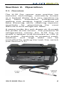
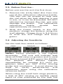
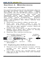
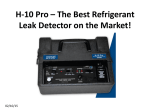
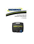
Instruction Manual
P/N: 3015-9005
Revision 0
September 2014
Product Leadership • Training • Service • Reliability
3015-9005 Rev 0
1
NOTICE
Specifications and information contained
in this document may change without
notice due to product improvements and
enhancements.
Bacharach, Inc. shall not be liable for
errors contained herein or for incidental
or consequential damages in connection
with the furnishing, performance, or use
of this material.
No part of this document may be
photocopied, reproduced, or translated
to another language without the prior
written consent of Bacharach, Inc.
Register your warranty by visiting
www.MyBacharach.com
Copyright © 2014, Bacharach, Inc.,
all rights reserved.
BACHARACH is a registered trademark of
Bacharach, Inc. All other trademarks,
trade names, service marks and logos
referenced herein belong to their
respective companies.
2
3015-9005 Rev 0
Section 1. Overview
1.1. Introduction
The H-10 Pro is the most versatile, high
performance leak detector available in
the industry today. It detects refrigerants
to pinpoint small, medium, and large
leaks quickly and efficiently. Review this
manual carefully and completely to
assure satisfactory product performance
and a long service life.
1.2. Safety Warnings
! WARNING: For your safety, DO NOT use
this device to detect for leaks of
refrigerants which are rated as
combustible/flammable
gases
(e.g.,
ASHRAE A2- or A3-rated refrigerants).
! HAZARDOUS AREA WARNING: This
instrument has not been designed to be
intrinsically safe for use in areas classified
as hazardous locations. For your safety,
DO NOT use it in hazardous (classified)
locations.
1.3. General Warnings
! WARNING: This device is not to be used
in any application that is beyond its
intended purpose or beyond the scope of
its specifications. For details on
appropriate use, refer to the rest of this
manual.
Before risking equipment
damage or personal injury, contact
Bacharach if you are unsure of the validity
of a particular application.
! IMPORTANT:
This analyzer is not
intended to be used on a continuous
basis.
3015-9005 Rev 0
3
! WARNING: Except for replacement of
consumables such as sensors, filters, and
battery, this analyzer should only be
opened and/or serviced by authorized
Bacharach personnel. Failure to comply
may void the warranty.
! WARNING: Do not store instrument or
its sensors with solvents or products that
contain solvents.
! IMPORTANT:
Hazards
Equipment
Damage
A. Submerging the probe in liquid will
damage the pump.
B. Exposing the probe to pure refrigerant
will severely reduce the life or destroy
the sensor. Life of the sensor is
directly proportional to the amount of
refrigerant that it is exposed to.
C. Exposure to high concentrations of
refrigerant may require adjustment of
sensor heat. Refer to section 3.1.
Sensor
Battery
1.4. Specifications
Spec
Type
Life
Charging
Type
[1]
Life
Calibration
Flexible Probe
Response
Flow Rate
Refrigerants
[2]
Detected
4
Description
12V lead-acid battery
3 hours (typical)
3-4 hours with wall
adapter (included)
Heated diode
1 year (typical)
As needed
(see Section 3.1)
4.5 ft. (1.4 m) length with
built-in filter
1 second
90 cc/min @ small setting
(typical)
All CFCs, HFCs, and HCFCs
3015-9005 Rev 0
Spec
Sensitivity
[3]
Indication
Auto adjust to
background
Warm-up
Visual
Audible
Weight
Dimensions
(LxWxH)
Operating
Conditions
Approvals
Warranty
Description
0.006 oz/yr stationary
0.1 oz/yr
moving per
SAE J2791
Yes, automatic mode only
2 min (typical)
Red LED in probe tip
Internal beeper or stereo
headphone jack
5.1 lb. (2.3 kg)
10.5 x 8.3 x 5.4 in.
(267 x 211 x 137 mm)
32 to 104 °F
(0 to 40° C)
CE
3 years
[1]
Based on normal use. Consistent and/or
constant exposure to high levels of refrigerant
will deteriorate the sensor life more quickly.
Increasing the sensor heater will also impact
sensor life.
[2]
DO NOT use this device to detect for leaks of
refrigerants which are rated as combustible/
flammable gases (e.g., ASHRAE A2- or A3-rated
refrigerants).
[3]
Sensitivity for R12, R22, R134a, R410a, R404a and
R507 when unit is set to small leak setting,
manual mode.
∇ ∇ ∇
3015-9005 Rev 0
5
Section 2. Operation
2.1. Overview
The H-10 Pro sensor uses positive ion
emission technology, commonly known
as a heated diode. It is very sensitive to
only halon substances (refrigerants)
making this product highly resistive to
false alarming, while retaining superior
sensitivity for pinpointing the most
difficult to find refrigerant leaks.
A pump inside the unit draws air through
the probe to the sensor. The presence of
refrigerant(s) causes the H-10 Pro to
sound a speaker and illuminate an LED in
the probe. Sensitivity to pinpoint small,
medium, and large leaks can be
controlled by setting the Leak Size switch
(see Section 2.2).
3015-9005 Rev 0
6
2.2. Panel Controls
3015-9005 Rev 0
7
2.3. Before First Use…
Before you use the unit the first time:
1. Remove the sticky-label disc from the
cap of the calibration reference bottle.
This disc can be reused to help seal
the vial when the leak detector is not
in use, or it can be discarded. DO NOT
attempt to unscrew the cap, you may
damage the bottle. The calibration
reference
bottle
should
last
approximately six months.
2. With the Power switch in the OFF
position, charge the battery using the
wall adapter. Charge time is 3-4 hours
or until the Full Charge LED turns
green.
2.4. Adjusting the Sensitivity
Set the Leak Size switch as follows.
SMALL switch position is the highest
sensitivity. The unit will indicate leak
rates of 0.006 oz/yr or greater and is used
for fluorine-based (HFC) gases like R134a.
This position also assures highest
repeatability for locating 0.1 oz/yr (or
greater) leaks per SAE J2791 moving
probe test conditions. It must always be
used to verify performance and
calibration when using the calibration
reference bottle.
When using the small leak range position,
a leak of HFC causing an audible signal
equal to that produced by the leak vial
8
3015-9005 Rev 0
has a leak
0.5 oz/year.
rate
of
approximately
MEDIUM switch position is used for
chlorine-based (CFC and HCFC) gases like
R12 and R22. The medium setting will
indicate approximately a 0.1 oz/yr (or
greater) leak rate. This position supports
finding leaks of approximately 0.5 oz/yr
(per SAE J2791) or greater. It is also
useful for locating larger HFC leaks.
When using the medium leak range
position on a CFC or HCFC system, this
leak rate would also be approximately
0.5 oz/year.
LARGE switch position is used to zero in
on large leaks of any refrigerant. The
large leak setting should be used in
conjunction with manual mode.
2.5. Auto Mode vs. Manual Mode
Auto mode enables the H-10 Pro to block
out background levels of refrigerants. This
greatly reduces and/or eliminates false
alarms while retaining sensitivity to
quickly locate small or medium size leaks.
Pinpointing leaks in this mode requires
continuous probe movement.
If the probe is held stationary over a leak,
the unit will zero out the leak, going into
the idle 1 tick/second condition. Briefly
moving the probe away from the leak (1-2
seconds) permits the unit to re-establish
sensitivity. Returning to the leak site, the
unit will alarm again. Continuing this
3015-9005 Rev 0
9
procedure will reliably and repeatedly
pinpoint the leak with each pass over the
leak site.
If a large leak is present, the auto zero
circuit may reduce sensitivity to an
unacceptable level to find small and
medium sized leaks. If this condition
exists, use the manual mode to pinpoint a
large leak. The manual mode is also an
effective means to determine if a large
leak of any refrigerant exists prior to
searching for leaks (see Section 2.4).
In Manual Mode the auto-zero circuit is
disabled. The unit will not zero the leak if
the probe is held over the leak site. This
mode may require frequent readjustment
of the Manual Balance control to
maintain the required 1 tick per second
that indicates proper adjustment and
calibration for all three sensitivity switch
positions. Manual mode provides greater
sensitivity than auto mode.
2.6. Setup
1. Turn the unit on.
2. Slide mode switch to AUTO position.
3. Slide the sensitivity switch to the
SMALL position.
4. Check Low Battery LED. If it glows red,
the battery needs charging, or you
10
3015-9005 Rev 0
may operate the unit using the
supplied wall adapter.
! NOTE: The sensor does not operate
when the low battery LED is on.
5. Check for sufficient airflow by pointing
the probe tip toward the floor,
covering it with your finger, then
releasing your finger. If proper flow
exists, the red ball should noticeably
rise up into the probe when you
uncover the probe tip. Note that the
actual height and final resting position
of the red ball are not important. If
the airflow ball does not rise:
a. Tap the probe lightly to ensure the
ball is not sticking.
b. Check the filter in the probe tip,
per Section 4.1. If the flow is still
insufficient, then the unit should
be sent for repair to the nearest
Authorized Service Center.
3015-9005 Rev 0
11
6. Allow two minutes for the sensor to
warm up, after which the flashing
probe light and sound indicator will
idle at approximately 1 click per
second.
7. Test operation by quickly touching the
probe tip to the top of the calibration
reference bottle (make sure sticky
label is removed). The unit should
respond with a rapid flash rate and
sound verifying correct operation and
optimum sensitivity. If the unit does
not respond correctly, see Section 3.1.
2.7. Checking for Leaks
! SAFETY WARNING: For your safety, DO
NOT use this device to detect for leaks of
refrigerants which are rated as
combustible/flammable
gases
(e.g.,
ASHRAE A2- or A3-rated refrigerants).
1.
Set the range switch to the
appropriate
range
to
ensure
maximum sensor life. If the leak size
is unknown, start at the Large leak
setting. This protects the sensor if a
large amount of gas is present.
! IMPORTANT: Exposing the sensor
to large amounts of refrigerant or
holding the probe over a leak for a
long period of time will significantly
shorten sensor life.
2.
Check for
progression
system.
leaks in a
through the
logical
entire
3.
If surfaces are dirty or wet, wipe
them off with a clean, dry cloth to
reduce filter clogging and extend
sensor life. DO NOT allow the unit to
draw in moisture. Use of the supplied
rubber probe tip helps prevent
moisture from being drawn into the
12
3015-9005 Rev 0
unit. Check for moisture before
inserting the probe into areas to be
checked for leaks.
4.
If leaks have not been detected using
the large leak setting: Try using the
medium or small setting as
appropriate.
If leaks have been detected using the
large leak setting: After locating and
repairing any leaks requiring the use
of the LARGE switch setting, switch
to the MEDIUM setting and verify the
system is free of leaks. For HFC
refrigerants (such as R134a), verify
the system is leak free using the
SMALL setting. For CFC and HCFC
systems (such as R12 and R22), the
MEDIUM setting is typically sufficient
to verify that the system is free of
leaks that require repairing.
After a leak is located and repaired,
clear the area with shop air, set the
unit on the small leak sensitivity, and
double check equipment for small
leaks.
∇ ∇ ∇
3015-9005 Rev 0
13
Section 3. Calibration and
Performance
3.1. Heater Adjustments
The sensor heater circuit can be adjusted
to control the sensitivity of the unit. A
heat setting that is too high causes
instability due to excessive sensitivity and
shortens sensor life. A heat setting that is
too low causes decreased sensitivity. The
heater
adjustment
LEDs,
heater
adjustment, and calibration reference
bottle is a unique system for setting the
correct sensor heat (sensitivity) for
optimum performance and long sensor
life. To check the heater setting:
1.
Slide the mode switch to AUTO, slide
the leak switch to SMALL, turn ON
the unit and allow it to stabilize
(approximately 2 minutes).
2.
When stabilized (at approximately 1
click per second), briefly touch the
probe tip to the calibration reference
bottle with the probe (ensure the
sticky label disc is removed from the
top of the bottle.
3.
If adjusted properly, the red LOW
LED will go out and the green OK LED
will briefly glow. This indicates the
sensor’s heat/sensitivity is adjusted
for optimum performance.
If the red LOW LED remains on when
you briefly touch the bottle, the
sensor heat is set too low and the
Heater Adjustment must be turned
slightly clockwise using a small
screwdriver. Allow unit to stabilize
about one minute and retest. Repeat
14
3015-9005 Rev 0
this procedure until the green OK LED
briefly glows.
If the red HIGH LED glows, the heat is
set too high and the heater
adjustment should be turned slightly
counterclockwise using a small
screwdriver. Allow the unit to
stabilize for about 1 minute and then
repeat the test.
Repeat this
procedure until the proper green OK
LED is indicated.
! NOTE: After initial check for correct
heater adjustment, disregard the
calibration LEDs. Their indication is
meaningless during subsequent leak
testing activity.
! NOTE:
Check for proper heat
adjustment on a daily basis. This assures
the H-10 Pro is calibrated for the correct
sensitivity for your daily test activity.
! NOTE:
Frequency of sensor heat
adjustment is a function of how much
exposure the sensor has to refrigerant.
Adjustment may be required every couple
of weeks for heavy duty service and once
every few months for light duty service.
! NOTE: Over the usable sensor life,
when heater adjustment is fully clockwise
and the green OK LED will not come on, it
is time to replace the sensor. (See Section
4.3.)
∇ ∇ ∇
3015-9005 Rev 0
15
Section 4. Maintenance
4.1. Replacing the Filter
To protect the pump from damage due to
foreign particles and moisture, replace
the filter as it becomes dirty. With
moderate use (15 to 30 minutes a day), it
is recommended that the filter be
replaced once per month. In dirty
environments or with heavy use, replace
the filter more frequently.
Always
replace the filter when it is visibly dirty or
wet. To replace the filter, follow the
steps below.
1. Remove the black rubber probe tip.
2. Pick out the filter with a pin or
tweezers. A fine screen will remain in
the tip of the probe nozzle (behind
where the filter sits).
3. Insert the new filter in the probe tip.
Make sure that the filter is firmly
seated against the screen.
4. Replace the rubber probe tip.
4.2. Replacing the Airflow Indicator
1. Remove the clear plastic section of the
probe tip by gently pulling and
twisting.
2. Turn the probe tip upside-down and
tap on it to remove the old airflow
indicator ball.
16
3015-9005 Rev 0
3. Insert the new airflow indicator ball
into the tip.
4. Reattach the probe tip to the probe
assembly.
4.3. Replacing the Sensor
The sensor needs to be replaced when
the H-10 Pro no longer responds to the
calibration reference bottle, even with
the heater adjustment turned fully
clockwise (make sure the reference bottle
contains some refrigerant).
1.
2.
3.
4.
Turn the leak detector OFF.
Turn the heater adjustment to its
full counterclockwise position.
Unplug the power cord and open
the sensor cover.
Allow the sensor to cool before
touching it.
! WARNING: Sensor temperature
may cause a burn if not allowed to
cool.
5.
6.
7.
Unplug and discard the sensor.
Insert a new sensor and close the
sensor cover.
Adjust the heater per Section 3.1.
∇ ∇ ∇
3015-9005 Rev 0
17
Section 5. Troubleshooting
5.1. Diagnosing Issues
P=Problem • C/S=Cause/Solution(s)
P
No response to calibration reference
bottle.
C/S Heat Adjustment is set too low or
bottle is empty. Readjust heater (see
“Heater Adjustment” section) or
replace bottle (3015-0864).
No air flow (indicator ball in probe
doesn’t float). Replace filter in probe
tip (3015-0784). Check for proper
pump operation.
Sensor exposed to excessive amounts
of halogen gas. Move probe to clean
atmosphere for several minutes
while sensor purges itself.
Water is in the probe. Turn unit off
and disconnect probe from chassis.
Remove screws and take out chassis.
Look at the underside of the leak
detector and follow the probe to the
pump. Remove this hose from the
pump. Blow clean air (5 psi) into the
probe tip for one or two minutes.
Reassemble unit and replace the
filter (3015-0784).
18
3015-9005 Rev 0
P
Erratic response occurs in all leak
positions.
C/S Filter is clogged. Replace the filter
(3015-0784).
Dirt is in the sensor. Remove sensor
and blow it out with clean air (not
over 10 psi). If unsuccessful, replace
the sensor (3015-0486). Replace the
filter (3015-0784).
Sensor has a short circuit. Replace
sensor (3015-0486).
Atmosphere is contaminated with
excessive refrigerant gas. Ventilate
the area.
P
Response is continuous (especially in
SMALL leak switch position).
C/S Detector sensitivity is excessive.
Readjust heater (see “Heater
Adjustment” section).
3015-9005 Rev 0
19
5.2. Limited Warranty
The purchaser is warranted that this leak
detector will be free of defects in material
and workmanship for 3 years from date
of purchase. This warranty does not
cover sensors, reference leaks, filters,
airflow balls, lamps, batteries, or probe
tips. Damages caused by the user will not
be covered.
If any defects are discovered during the
warranty period, an Authorized Service
Center will repair or replace the unit at
their option.
The foregoing limited
warranty is exclusive and in lieu of all
other warranties, whether written or
implied,
and
no
warranty
of
merchantability or fitness for purpose will
apply.
5.3. Repair Information
Should it become necessary to repair your
H-10 Pro, please contact an authorized
service center. Units should be carefully
packed to prevent shipping damage and
shipped prepaid.
20
3015-9005 Rev 0
5.4. Spare Parts
Part
Number
Description
3015-8004
H-10 Pro Refrigerant Leak
Detector, battery, charger,
and North American plug
3015-8005
H-10 Pro Refrigerant Leak
Detector, battery, charger,
and plug set (North
American and international)
3015-0326
14” flexible probe extension
3015-5812
Wall adapter with North
American plug
3015-0119
Wall adapter with North
American and international
plugs
3015-0895
Battery clamp/cigarette
adapter assembly
3015-0641
Clear probe tip
3015-0680
Rubber probe tip
3015-0486
Replacement sensor
3015-0781
Tune-up kit (sensor, 100
filters, 3 airflow balls, 3
rubber probe tips, and
calibration bottle)
3015-0784
Maintenance kit (100 filters,
3 airflow balls, 3 rubber
probe tips, and calibration
bottle)
3015-0737
Maintenance kit (12 filters, 3
airflow balls)
3015-0864
Calibration reference bottle
3015-0103
Battery
0028-0002
Headphones
3015-0095
Shoulder strap
3015-9005 Rev 0
21
5.5. Authorized Service Centers
Replacement parts and service can be
obtained by contacting one of the
following Bacharach Service Centers.
United States
Bacharach, Inc.
621 Hunt Valley Circle
New Kensington, PA 15068
Phone: 724-334-5051
Fax:
724-334-5723
Email: [email protected]
Canada
Bacharach of Canada, Inc.
20 Amber Street Unit #7
Markham, Ontario L3R 5P4
Canada
Phone: 905-470-8985
Fax:
905-470-8963
Email: [email protected]
∇ ∇ ∇
22
3015-9005 Rev 0
Declaration of Conformity
Manufacturer
Bacharach, Inc.
621 Hunt Valley Circle
New Kensington, PA 15068
Year declared:
2012
Product(s):
Refrigerant Leak Detector
Model(s):
H-10 Pro
The undersigned hereby declares that the above
referenced product is in conformity with the
provisions of the following standards and is in
accordance with the following directive.
Directive:
2004/108/EC
EMC Directive
Standard(s):
EN 50270: 2006
Electromagnetic
Compatibility: Electrical
Apparatus for the Detection
and Measurement of
Combustible Gases, Toxic
Gases or Oxygen
Signature:
Name:
Title:
Date:
Aaron Kennison
Engineering Manager
September 23, 2014
The technical documentation file required by this directive is
maintained at the corporate headquarters of Bacharach, Inc.
3015-9005 Rev 0
23
World Headquarters
621 Hunt Valley Circle
New Kensington, Pennsylvania 15068
Phone: 724-334-5000 • Fax: 724-334-5001
Toll Free: 1-800-736-4666
Website: www.MyBacharach.com
E-mail: [email protected]
24