1
Synergy Controller
April 2008, Revision P5
Application Note 8
Tidal Engineering Corporation © 2008
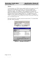
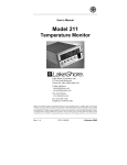
Synergy Simple Communications
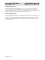
The Synergy SimpleComm application is an all in one communications package
designed to be used with the Synergy Controller. It provides a simple interface for
sending and receiving commands over: RS-485, RS-232, IEEE 488 & TCP/IP.
The Synergy Controller supports over 130 unique commands, allowing for complete
control and monitoring of your chamber from remote locations. You can find the
Synergy Controller command set at Tidal Engineering’s website
www.tidalengineering.com. Navigate to the Synergy Controller page and look under
the general information section for the Synergy Communications Commands
Acrobat Reader file. This file contains a spreadsheet of all the available
communication commands. The source code is also available on the web site for
users who would like to develop their own communications programs. The source
files are located on the Synergy Controller page and are linked to under the
Downloads section.
Figure 1 – Synergy SimpleComm
Page 1 of 18
Synergy Controller
April 2008, Revision P5
Application Note 8
Tidal Engineering Corporation © 2008
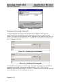
Installing SimpleComm
Insert the setup disk in the CDROM drive of your PC. Through your windows
explorer, find the drive and double click on the setup.exe file. Alternatively, you
may press Start / Run from your desktop. Follow the directions on the screen. You
may be prompted to insert a second or third installation disk.
Connecting SimpleComm
The PC on which SimpleComm is running must be connected to the chamber. The
method of connection depends on the desired mode of communications. RS-485
and 232 use serial cables, IEEE 488 uses a GPIB cable and TCP/IP uses network
cables such as CAT5.
Page 2 of 18
Synergy Controller
April 2008, Revision P5
Application Note 8
Tidal Engineering Corporation © 2008
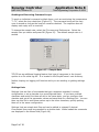
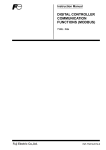
RS-485
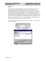
To communicate over RS-485, plug a serial cable into the back of your PC
and connect the other end to the serial port on the chamber. On the
SimpleComm, press the RS-485 tab and set the port number to the same
port number specified on your PC (Figure 2). To determine the port settings
on the PC, go to Start/Settings/System, select the hardware tab, select
Device Manager and expand the Ports icon. The Synergy Controller’s RS-485
port settings are hard-coded to: 9600 baud rate, no parity, 8 data bits and 1
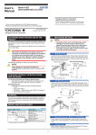
stop bit. Next, set SimpleComm’s RS-485 address to the same address as
the Synergy Controller V (Figure 3). The RS-485 Mode must be set to User
Comms, if it reads UUT Sensors, change the setting.
Once the settings are complete, press the connect button. The status label
will read: port open.
Figure 2 – SimpleComm
Figure 3 – Synergy Controller V
Page 3 of 18
Synergy Controller
April 2008, Revision P5
Application Note 8
Tidal Engineering Corporation © 2008
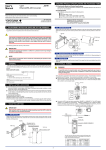
RS-232
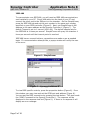
To communicate over RS-232, plug a serial cable into the back of your PC
and connect the other end to the serial port on the chamber. On the
SimpleComm, press the RS-232 tab and set the port number to the same
port number specified on your PC (Figure 4). To determine the port settings
on the PC, go to Start/Settings/System, select the hardware tab, select
Device Manager and expand the Ports icon. The Synergy Controller’s RS-232
port settings are hard-coded to: 19200 baud rate, no parity, 8 data bits and
1 stop bit (Figure 5). RS-232 does not need address settings.
Once the settings are complete, press the connect button. The status label
will read: port open.
Figure 4 – SimpleComm
Figure 5 – Synergy Controller V
Page 4 of 18
Synergy Controller
April 2008, Revision P5
Application Note 8
Tidal Engineering Corporation © 2008
IEEE 488
To communicate over IEEE 488, you will need an IEEE 488 communications
card installed in your PC. Plug a 488 cable into the back of your PC and
connect the other end to the 488 port on the chamber. On the SimpleComm,
press the IEEE 488 tab and set the port number to the same port number
specified on your GPIB controller (Figure 6). Next, set SimpleComm’s 488
address to the same address as the Synergy Controller V (Figure 7). The
default Timeout is set to 1 second (1000 ms). The default sample rate for
the IEEE 488 is 4 times per second. SimpleComm will query the chamber 4
times per second until the timeout period is reached.
IEEE 488 has no connect buttons; connections are made on an as needed
basis. If a communication attempt fails, a popup window will notify the user
of the error.
Figure 6 – SimpleComm
Figure 7 – Synergy Controller V
To view IEEE specific controls, press the properties button (Figure 6). From
this window you may view and set the GPIB port and address (Figure 8).
You can test the IEEE connection by pressing the test button. This test sends
the *IDN? Command to the Synergy Controller V. The response will be
displayed in the response test box (Figure 9). If there is no response it will
display an error message.
Page 5 of 18
Synergy Controller
April 2008, Revision P5
Application Note 8
Tidal Engineering Corporation © 2008
Figure 8 – TMW GPIB Control
Figure 9 – TMW GPIB Control
Page 6 of 18
Synergy Controller
April 2008, Revision P5
Application Note 8
Tidal Engineering Corporation © 2008
TCP/IP
To communicate over TCP/IP, plug a network cable into the back of your PC
and connect the other end to your LAN. You must also connect your
chamber to a LAN. The Synergy Controller V requires a DHCP router to
dynamically assign it an IP address. Once assigned the IP Address will
appear in the Ethernet folder of the Synergy Controller (Figure 11). Set the
SimpleComm to the same address (Figure 10). The default port for the
chamber is 5000; always set SimpleComm’s port to 5000. To enable the
TCP/IP communications on the chamber, go to the TCP/IP Server folder and
set it to enabled (Figure 12).
Once the settings are complete, press the connect button. The status label
will read: socket connected.
Figure 10 – SimpleComm
Figure 11 – Synergy Controller V
Page 7 of 18
Synergy Controller
April 2008, Revision P5
Application Note 8
Tidal Engineering Corporation © 2008
Figure 12 – Synergy Controller V
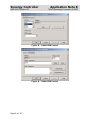
Sending and Receiving Commands
To send individual commands, first connect to the chamber, then type the
command into the command text box, then either hit enter or press the send
button. The reply from the chamber will be displayed in the response text box. All
query commands are preceded with a “?” and all set commands are preceded with
an “=” (Figures 13 & 14).
Figure 13 – Sending Query Commands
Figure 14 – Sending Set Commands
The RS-485 commands are a special case. Normally commands over RS-485 are
preceded by a greater than symbol and the address, “>02 ? CAL2” and all
responses are similarly preceded, “<02 0.00”. SimpleComm automatically prefixes
the commands so it is not necessary for you to.
Page 8 of 18
Synergy Controller
April 2008, Revision P5
Application Note 8
Tidal Engineering Corporation © 2008
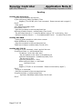
Sending and Receiving Command Loops
To send an individual command multiple times, such as monitoring the temperature
“? C1”, select the loop check box (Figure 13). The command string will be sent
once a second as long as the loop box remains checked. The response box will
display each reply as it is received.
To change the sample rate, select the File menu and Preferences. Select the
sample rate you desire and press OK (Figure 15). The default sample rate is 1
second.
Figure 15 – Sample Rate
TCP/IP has an additional logging feature that logs all responses to the looped
queries to a file called log.txt. It is located in the SimpleComm’s root directory.
Neither looping nor logging will function while you are sending or getting settings
lists.
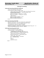
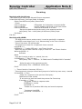
Settings Lists
Settings Lists are lists of commands that get a snapshot chamber’s current
configuration or set a chamber to a preconfigured state. If you have multiple
chambers and would like them all set to the same state, you can configure one
chamber and get all its parameter values and save them to a Settings List. You can
then use this list to send these values up to the other chambers, quickly putting
them all in the same configuration.
Settings Lists are simple text files and can be edited in notepad if desired.
Commented lines must be preceded by a double slash. When loaded the comments
are displayed in the Memo field (Figure 16).
Page 9 of 18
Synergy Controller
April 2008, Revision P5
Application Note 8
Tidal Engineering Corporation © 2008
Figure 16 – Settings Lists
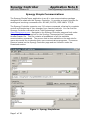
Downloading, Editing and Uploading Chamber Settings
When upgrading a chamber to a new application version you will lose all your
chambers configuration settings and PID tunings. It is a good idea to save all the
configuration settings in a separate text file before upgrading. After you upgrade
you can then reconfigure your chamber to all the previous settings and PID tunings.
You may use a simple checklist, such as the one available in the User Manual, and
record all the items manually. Alternatively, you may use SimpleComm.
SimpleComm has simplified the task of downloading and uploading chamber
settings by assembling a precompiled list of commands to automatically query your
chambers settings, saving them and uploading them to your new chamber.
To open a Settings List press the Load List button. Select a file and press OK. The
name of the loaded file is displayed on the title bar. The content of the list appears
in the Settings List data grid. The Settings column holds the commands. The Value
Page 10 of 18
Synergy Controller
April 2008, Revision P5
Application Note 8
Tidal Engineering Corporation © 2008
column holds the values for the commands. The Set Response column holds the
chamber’s responses from set commands.
To edit an item in the list, press the Edit List button. Enter your changes and press
Save As or Cancel. Clicking in the Comments box and typing additional lines will
add text to the Comments field. You can clear the entire list, including commands,
by pressing the Clear List button. Alternatively you can clear selected columns by
highlighting the column and pressing the Clear Col button.
Getting Data
To get the current configuration of a chamber, load a Settings List that is a list of
commands. SimpleComm automatically installs a master list of the most important
commands. The list is named “VTV GET MASTER.VTS” and it is stored in the root
installation directory of the SimpleComm program. Once loaded, make sure you
are connected and press the Get List button. SimpleComm will query the chamber
one command at a time until it has gone through the entire list. After each query is
sent to the chamber, SimpleComm will wait until it receives a response before
trying to get the next value. As each response arrives it is placed in the
corresponding cell in the Value column. When the entire list has been transferred a
popup window will state that the transfer is complete.
After you have gathered your chambers settings, press the Save List button to save
the list. SimpleComm automatically installs a master list of the most important
commands and their respective settings for a new chamber. The list is named “VTV
SET MASTER.VTS” and it is stored in the root installation directory of the
SimpleComm program. We suggest saving your new chamber settings either over
this file or in a new file with an appropriate descriptive name identifying the
chamber.
Sending Data
To send your upgraded chamber the original configuration settings, load the
Settings List you created in the previous step. Once loaded, make sure you are
connected and press the Send button. SimpleComm will set the chamber one
command at a time until it has gone through the entire list. After each set
command is sent to the chamber, SimpleComm will wait until it receives an “OK”
response before trying to get the next value. As each “OK” response arrives it is
placed in the corresponding cell in the Set Response column. When the entire list
has been transferred and popup window will state that the transfer is complete.
Get Settings List Example:
\\Serial Number: 06/0201
\\Version: 1.4.10
CF
CAL1
A1L
Page 11 of 18
Set Settings List Example:
\\Serial Number: 06/0201
\\Version: 1.4.10
CF 0
CAL1 0.00
A1L -200
Synergy Controller
April 2008, Revision P5
Application Note 8
Tidal Engineering Corporation © 2008
Important Note:
Make sure that you always have the chamber set to the same temperature scale for
downloading and uploading operations. If you download from a chamber in
Centigrade mode, then upload to a chamber that is in Fahrenheit, you will have
numerous incorrect settings.
Additionally, all Communication settings, cascade registration keys and web server
registration keys will need to be recorded and reentered manually. The table below
is a list of these settings. These settings are not part of the sensitive tunings of
you chamber and are not absolutely necessary to save.
Registration Keys
Web Server Registration Key
Cascade Registration Key
Communications
RS-485
RS-485 Mode
Station Address
Number of UUTs
IEEE-488
IEEE 488 Address
Ethernet
IP Address Selection
Ethernet Address
Ethernet Subnet Mask
Ethernet Gateway
Web Server
Web Server On/Off
Web Server Login Name
Web Server Password
Web Server Address
TCP/IP Server
TCP/IP Server On/Off
Page 12 of 18
Synergy Controller
April 2008, Revision P5
Application Note 8
Tidal Engineering Corporation © 2008
Visual Basic Source Code
Tidal Engineering provides the source code for the Synergy SimpleComm
application as a reference guide for developers. We recommend that you use Visual
Basic 6.0 or higher and Windows 2000 or higher.
Before you install the source code, you must install the Synergy SimpleComm
application, which contains a TMW GPIB component that is needed to run the
program in Visual Studio. To install the source code, download the files from the
Tidal Engineering web site. Double click on the Setup.exe file and follow the
installation directions. Start Visual Studio and open the Visual Basic Project file,
SimpleComm.vbp. The source code and forms are fully editable.
Communications Source Code
There are several key code portions that form the basis of communication over
serial ports, TCP/IP and GPIB. The selections are discussed below and are broken
into three areas: settings & connecting, sending data, and receiving data. These
sections of code can be cut and pasted into your own programs, thus adding quick
and simple communication routines to your applications.
Page 13 of 18
Synergy Controller
April 2008, Revision P5
Application Note 8
Tidal Engineering Corporation © 2008
Setting & Connecting
Setting & Connecting with RS 232 & RS 485
‘ If your not connected, then connect
If (Not MSComm1(Index).PortOpen) Then
' Set the Comm Port number to the value in the Comm Port text box
MSComm1(Index).CommPort = Val(txtPort(Index).Text)
‘ Set Baud Rate and Parity
MSComm1.Settings = "9600,N,8,1" ‘RS 485
MSComm1.Settings = "19200,N,8,1" ‘RS 232
‘ Open the port
MSComm1(Index).PortOpen = True
MSComm1(Index).InputLen = 0
MSComm1(Index).RThreshold = 1
End If
Setting & Connecting with GPIB
‘ Set the timeout to the value in the timeout box (milliseconds)
TMWControl1.TimeOut = Trim(Str(Val(txtTimeout488.Text)))
‘ Set the address to the value in the address box
’ final address will appear as: GPIB0::1::INSTR
TMWControl1.address = "GPIB" & Trim(Str(Val(txtPort(Index).Text))) & "::" &
Trim(Str(Val(txtAddress(Index).Text))) '& "::INSTR"
Setting & Connecting with TCP/IP
‘ If your not connected, then connect
If tcpClient1.State <> sckConnected Then
'`IP address "###.###.###.###"
‘ Set the address to the value in the address box
tcpClient1.RemoteHost = txtAddress(Index).Text
‘ Set the port to the value in the port box
tcpClient1.RemotePort = txtPort(Index).Text
‘ Close it first – just in case
While tcpClient1.State <> sckClosed
tcpClient1.Close
Wend
‘ Connect
tcpClient1.Connect
End If
Page 14 of 18
Synergy Controller
April 2008, Revision P5
Application Note 8
Tidal Engineering Corporation © 2008
Sending
Sending with Serial Ports
‘ If your not connected, tell the user
If (Not MSComm1(Index).PortOpen) Then
MsgBox ("The RS 485 port is not connected. Please connect and try again.")
End If
' Clear buffer
a$ = MSComm1(Index).Input
txtIn(Index).Text = ""
‘ Send the command in the command text box
MSComm1(Index).Output = txtOut(Index).Text & vbCr
' The 485 send requires a ">" and the address such as "02" in the string. Use:
‘ MSComm1(Index).Output = ">" & cboAddress485.Text & " " & txtOut.Text & vbCr
Sending with GBIB
‘ Create a global variable to hold a timer counter
Global GPIBResult as Integer
‘ Send the command in the command text box
TMWControl1.Output (txtOut(Index).Text & vbCr)
Sending with TCP/IP
' If tcp/ip1 is not connected, close it and tell the user
If tcpClient1.State <> sckConnected Then
'IP address "###.###.###.###"
‘ Set the address to the value in the address box
tcpClient1.RemoteHost = txtAddress(Index).Text
‘ Set the port to 5000
tcpClient1.RemotePort = 5000
While tcpClient1.State <> sckClosed
tcpClient1.Close
Wend
MsgBox ("TCP/IP1 is not connected. Please connect and try again.")
End If
' If tcp/ip1 is connected,
‘ Send the command in the command text box
If tcpClient1.State = sckConnected Then
tcpClient1.SendData txtOut(Index).Text & vbCr
End If
Page 15 of 18
Synergy Controller
April 2008, Revision P5
Application Note 8
Tidal Engineering Corporation © 2008
Receiving
Receiving with Serial Ports
‘ MSComm1 is the name of the Microsoft Comm component
Private Sub MSComm1_OnComm(Index As Integer)
Select Case MSComm1(Index).CommEvent
' Events
Case comEvSend
' SThreshold # of characters in transmit buffer.
Case comEvEOF
' An EOF charater was found in the input stream
Case comEvReceive
' Received RThreshold # of chars
‘ Receive the data and write the result in the response text box
txtIn(Index).Text = txtIn(Index) & MSComm1(Index).Input
End Select
End Sub
Receiving with GPBIB
' The GPIB contro has no receive event, it must be queried for a response.
’ timerGPIB counts down from 2 to 0, decrementing in the Timer1 function.
‘ Timer1 fires every 250 milliseconds
‘ This allows us to check for a response 4 times a second.
timerGPIB = 2
GPIBResult = "" 'tracks GPIB reply - see Timer1 function
' While loop will exit after receives a reply or times out - see Timer1 function
While timerGPIB > 0
DoEvents
Wend
‘ If we don’t receive a reply in 1 second, time out
If GPIBResult = "" Then 'no reply
txtIn(Index).Text = "Timeout: " & TMWControl1.TimeOut/1000 & "seconds."
Else
‘ Write the reply to the response text box
txtIn(Index).Text = GPIBResult 'GPIB value
End If
‘--- Timer1 function: fires every 250 ms --‘ Timer1 queries 4 times per second and jumps out of while loop once every 1 second
If timerGPIB > 0 Then
' Check for a response to the previous Send query
TMWControl1.Enter result$
' If we receive a result we break the previous Do Events loop
If result$ <> "" Then
‘Set global variable to response value
GPIBResult = result$
timerGPIB = 0
‘ Breaks out of previous While loop and records response
Else
' Increment timerGPIB
timerGPIB = timerGPIB – 1
End If
End If
Page 16 of 18
Synergy Controller
April 2008, Revision P5
Application Note 8
Tidal Engineering Corporation © 2008
Receiving with TCP/IP
‘ tcpClient1 is the name of the Microsoft TCP Client component
Private Sub tcpClient1_DataArrival(ByVal bytesTotal As Long)
Dim strData As String
' Get data
tcpClient1.GetData strData
‘ Write the response in the response test box
txtIn(3).Text = Replace(strData, vbCrLf, "", 1, -1, vbBinaryCompare)
End Sub
This concludes the SimpleCommdemonstration. For more information concerning
SimpleComm, consult the Synergy Controller Technical Manual on our website and/or
contact technical support at the factory.
Page 17 of 18
Synergy Controller
April 2008, Revision P5
Application Note 8
Tidal Engineering Corporation © 2008
About Tidal Engineering
Headquartered in Randolph, NJ, Tidal Engineering Corporation has been designing and
building award-winning embedded hardware and software for test and measurement and
data acquisition applications since 1992. The company is recognized for technical expertise
in such areas as Embedded IEEE 488, and turnkey SCADA (Supervisory Control and Data
Acquisition) systems. Tidal’s products are available exclusively through ADI American
Distributors Inc., an ISO-9002 certified distributor of electronic and electromechanical
components and assemblies.
Tidal Engineering Corporation
2 Emery Avenue
Randolph, NJ 07869
Tel: 973/328-1173
Fax: 973/328-2302
www.TidalEng.com
[email protected]
Page 18 of 18