1
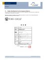
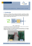
USER MANUAL Transmitter Module PTM 430J May 7, 2014 Observe precautions! Electrostatic sensitive devices! Patent protected: WO98/36395, DE 100 25 561, DE 101 50 128, WO 2004/051591, DE 103 01 678 A1, DE 10309334, WO 04/109236, WO 05/096482, WO 02/095707, US 6,747,573, US 7,019,241 EnOcean GmbH Kolpingring 18a 82041 Oberhaching Germany Phone +49.89.67 34 689-0 Fax +49.89.67 34 689-50 [email protected] www.enocean.com Subject to modifications PTM 430J User Manual May 7, 2014 Page 1/18 USER MANUAL 1.1 PTM 430J REVISION HISTORY The following major modifications and improvements have been made to the first version of this document: No 1.0 1.1 Major Changes Finalized version Added certification information Published by EnOcean GmbH, Kolpingring 18a, 82041 Oberhaching, Germany www.enocean.com, [email protected], phone ++49 (89) 6734 6890 © EnOcean GmbH All Rights Reserved Important! This information describes the type of component and shall not be considered as assured characteristics. No responsibility is assumed for possible omissions or inaccuracies. Circuitry and specifications are subject to change without notice. For the latest product specifications, refer to the EnOcean website: http://www.enocean.com. As far as patents or other rights of third parties are concerned, liability is only assumed for modules, not for the described applications, processes and circuits. EnOcean does not assume responsibility for use of modules described and limits its liability to the replacement of modules determined to be defective due to workmanship. Devices or systems containing RF components must meet the essential requirements of the local legal authorities. The modules must not be used in any relation with equipment that supports, directly or indirectly, human health or life or with applications that can result in danger for people, animals or real value. Components of the modules are considered and should be disposed of as hazardous waste. Local government regulations are to be observed. Packing: Please use the recycling operators known to you. © 2014 EnOcean | www.enocean.com PTM 430J User Manual | Page 2/18 USER MANUAL 1.1 PTM 430J TABLE OF CONTENT 1 RELATED DOCUMENTS ................................................................................... 4 2 2.1 2.2 2.3 2.4 2.5 GENERAL DESCRIPTION ................................................................................. 4 Basic Functionality ......................................................................................... 4 Technical Data .............................................................................................. 4 Physical Dimensions....................................................................................... 5 Environmental Conditions ............................................................................... 6 Ordering Information ..................................................................................... 6 3.1 3.2 3.3 3.4 3.5 3.6 3.7 3.8 FUNCTIONAL DESCRIPTION ............................................................................ 7 Block diagram ............................................................................................... 7 Pin out ......................................................................................................... 7 Pin Description and operational characteristics .................................................. 8 Configuration Interface .................................................................................. 9 Absolute maximum ratings (non operating) .................................................... 10 Maximum Ratings (operating) ....................................................................... 10 Radio telegram ............................................................................................ 11 Transmit timing ........................................................................................... 12 4.1 4.2 4.3 4.4 4.5 APPLICATIONS INFORMATION ....................................................................... 13 How to connect an energy harvester .............................................................. 13 How to generate an equivalent energy pulse ................................................... 13 Antenna ..................................................................................................... 14 Layout recommendations ............................................................................. 15 Transmission range ..................................................................................... 16 3 4 5 Radio Certification for the Japanese Market ..................................................... 17 5.1 Label Information ........................................................................................ 18 © 2014 EnOcean | www.enocean.com PTM 430J User Manual | Page 3/18 USER MANUAL 1.1 PTM 430J 1 RELATED DOCUMENTS In addition to this document additional information is available on our web site: Proposal for mechanical integration with ECO 200 in 2D and 3D format Footprint with positions of pads available in Protel and Gerber format AN102: Antenna Basics – Basic antenna design considerations for EnOcean based products 2 GENERAL DESCRIPTION 2.1 Basic Functionality The radio transmitter module PTM 430J from EnOcean enables the implementation of wireless sensors and switches without batteries. Key applications are handheld remote controls or industrial switches. Functional Principle When an energy pulse is supplied (e.g. by ECO 200 from EnOcean) an RF telegram is transmitted including a unique 32 or 48 bit module ID, the polarity of the energy pulse, and the operating status of 4 digital inputs. The RPS telegram (EnOcean Radio Protocol 2) can be configured if other content is needed. PTM 430J can be connected to ECO 200 via a contact spring. There are two meander structures on the PCB which allow usage of a rubber pad to set the level of two digital inputs. Alternatively PTM 430J can be mounted as an SMD component onto a host PCB. In this case energy supply pins and digital input pins are accessible via contact pads. THT soldering of whip antenna has to be considered. 2.2 Technical Data Power supply Antenna Frequency Transmission power Data rate / Modulation type Telegram type Digital inputs Transmission range PCB size © 2014 EnOcean | www.enocean.com ECO 200 or equivalent energy pulse pre-installed whip antenna 928.350 MHz typ. 0 dBm at antenna base 125 kbps /FSK RPS type 2 (EnOcean Radio Protocol 2) 4 up to 200 m free field, up to 20 m indoor 26.2 x 21.15 x 3.5 mm PTM 430J User Manual | Page 4/18 USER MANUAL 1.1 PTM 430J Physical Dimensions PTM 430J 2.3 © 2014 EnOcean | www.enocean.com PTM 430J User Manual | Page 5/18 USER MANUAL 1.1 PTM 430J 2.4 Environmental Conditions Operating temperature -25 °C … +65 °C Storage temperature -40 °C … +85 °C Humidity 2.5 0% … 93% r.h., non-condensing Ordering Information Type Ordering Code PTM 430J S3061-A430 © 2014 EnOcean | www.enocean.com Frequency 928.350 MHz Note Whip antenna mounted, trays in card board box PTM 430J User Manual | Page 6/18 USER MANUAL 1.1 PTM 430J 3 FUNCTIONAL DESCRIPTION 3.1 Block diagram At power-up by an energy pulse at AC1, AC2 a DC voltage is provided to the internal micro controller. The microcontroller reads the polarity of the supply voltage pulse and the status of the digital inputs A0, A1, B0, B1. After that 2 identical radio telegrams calculated from the status of these inputs are transmitted. PTM 430J PTM33x CFG A0 A1 RF_WHIP B0 µC B1 RF GND GND RF_50 Polarity Detection AC1 AC2 3.2 Power Converter Pin out GND 1 CFG 2 B0 3 GND 4 B1 5 A0 6 GND 7 A1 8 AC1 AC2 T1 T4 T3 T8 T6 AC2 T5 T7 T9 AC1 T2 16 AC1 15 AC2 14 GND 13 V+ 12 GND 11 RF_50 10 GND 9 RF_WHIP On back side of PCB © 2014 EnOcean | www.enocean.com PTM 430J User Manual | Page 7/18 USER MANUAL 1.1 PTM 430J 3.3 Pin Description and operational characteristics Symbol Function Characteristics GND V+ Ground connection For test purposes only O-Button Rocker B Must be connected to GND Do not connect Digital input, leave open or connect to Internal pull-up Digital input, leave open or connect to Internal pull-up Digital input, leave open or connect to Internal pull-up Digital input, leave open or connect to Internal pull-up Internal pull-up ECO 200 or equivalent energy pulse ECO 200 or equivalent energy pulse Output for whip antenna 50 Ohm output for external antenna, not available for PTM 430J See 3.4 B0 I-Button Rocker B B1 O-Button Rocker A A0 I-Button Rocker A A1 CFG AC1 AC2 RF_WHIP RF_50 For test purposes only Input for ECO 200 Input for ECO 200 RF output RF output T1-9 Configuration Interface © 2014 EnOcean | www.enocean.com GND GND GND GND PTM 430J User Manual | Page 8/18 USER MANUAL 1.1 PTM 430J 3.4 Configuration Interface Via the SPI programming interface the telegram content can be modified: 1. PTM 430J needs to be connected by needle bed adapter with the SPI programming pins: Reset, PROG_EN, ADIO7, SCSEDIO0, SCLKDIO1, WSDADIO2 and RSDADIO3. 2. Use programmer board EOP 350 (part of EnOcean Development Kit) as interface between needle bed adapter and PC. Pad Symbol Function Characteristics T1 T2 T3 T4 T5 T6 VDD GND SCSEDIO0 SCLKDIO1 WSDADIO2 RSDADIO3 RESET Supply voltage Ground connection SPI chip select SPI serial clock SPI input SPI output Reset Interface to programmer; Max. 3.3 V Interface to programmer Interface to programmer Interface to programmer Interface to programmer Interface to programmer Interface to programmer, internal pull down ADIO7 Sync output PROG_EN Interface to programmer Enable program- HIGH: programming mode active ming mode LOW: operating mode Internal pull-down T7 T8 T9 3. PTM 430J telegrams can be configured via PC software Dolphin Module Configurator (part of DolphinSuite). Use this tool to change telegram coding and/or module ID length 32/48 bit to customer specific needs. Default configuration of the outgoing telegram coding is corresponding to the profile definition of the EEP F6-02-04. Please see chapter 3.7. © 2014 EnOcean | www.enocean.com PTM 430J User Manual | Page 9/18 USER MANUAL 1.1 PTM 430J By default the Telegram: Energy bow released and B0 button pressed. POL: 1, B0: 0, B1: 1, A0: 1, A1: 1 This Telegram is used to transmit a 48 bit ID. This can be also corrected by Dolphin Module Configurator. 3.5 Absolute maximum ratings (non operating) Symbol AC1 AC2 GND A0 A1 B0 B1 3.6 Parameter Supply voltage Ground connection Min 0 0 0 Max 6.4 0 0 Units V V V Voltage digital input pins Maximum Ratings (operating) Symbol AC1 AC2 GND A0 A1 B0 B1 Parameter Supply voltage Ground connection Min 0 0 0 Max 6.0 0 0 Units V V V Voltage digital input pins © 2014 EnOcean | www.enocean.com PTM 430J User Manual | Page 10/18 USER MANUAL 1.1 PTM 430J 3.7 Radio telegram In default configuration PTM 430J transmits the same telegrams as a PTM 210J radio switch (EnOcean radio protocol 2): R-ORG FUNC TYPE : : : F6 02 04 Reserved is required to be 0. Telegram definitions: Offset Size Bitrange Data Shortcut 0 1 DB0.7 Energy bow EBO State of the energy bow. 1 1 DB0.6 Button coding EBO Signalize button coding.. 2 2 DB0.5DB0.4 0 1 DB0.3 BI RBI State I of the rocker B. 0 1 DB0.2 B0 RB0 State 0 of the rocker B. 0 1 DB0.1 AI RAI State I of the rocker A. 0 1 DB0.0 A0 RA0 State 0 of the rocker A. © 2014 EnOcean | www.enocean.com Description Valid Scale Range Enumeration: 1: pressed 0: released Enumeration: 0: button Unit Reserved Enumeration: 1: pressed 0: not pressed Enumeration: 1: pressed 0: not pressed Enumeration: 1: pressed 0: not pressed Enumeration: 1: pressed 0: not pressed PTM 430J User Manual | Page 11/18 USER MANUAL 1.1 PTM 430J R-ORG FUNC TYPE : : : F6 04 02 Reserved is required to be 0. Telegram Definition: Offset Size Bitrange Data Shortcut Description 0 1 DB0.7 Energy bow EBO State of the energy bow. 1 1 DB0.6 Button coding EBO Signalize button coding.. 2 3 DB0.5 DB0.3 5 1 DB0.2 6 2 DB0.1 DB0.0 Valid Scale Range Enumeration: 1: card inserted 0: taken out Enumeration: 0: button Unit Reserved State of card SOC State of the card. Enumeration: 1: card inserted 0: taken out Reserved When card is inserted field EBO and SOC are both having value 1. When take out, both are having value 0. This coding is required to have a context-less translation of RPS profiles between ERP 1 and ERP 2. 3.8 Transmit timing The setup of the transmission timing allows avoiding possible collisions with data packages of other EnOcean transmitters as well as disturbances from the environment. With each transmission cycle, two identical sub telegrams are transmitted within 40 ms. The transmission of a sub telegram lasts approximately 0.7 ms. The delay between the two transmission bursts is affected at random. After sending of two sub telegrams there will be a pause of 50ms to be conform to the duty cycle rules of ARIP. Pushing the button during this pause will be ignored. © 2014 EnOcean | www.enocean.com PTM 430J User Manual | Page 12/18 USER MANUAL 1.1 PTM 430J 4 APPLICATIONS INFORMATION 4.1 How to connect an energy harvester PTM 430J can be connected to ECO 200 without soldering. ECO 200 provides contact springs which can directly be connected to contact pads of PTM 430J. The contact pads on the bottom of the PCB are shown below (left). A second orientation where PTM 430J is rotated 180° with respect to ECO 200 is also possible as shown with dashed lines. 4.2 How to generate an equivalent energy pulse PTM 430J can also be operated from an external equivalent energy pulse. As the source impedance is not known a procedure is defined how to find the needed duration of the pulse. The pulse must provide a voltage between 5 V and 6 V for maximum 10 ms time. storage capacitor The length of this supply pulse needs to be defined by measuring the remaining voltage on the storage capacitor after the 2nd subtelegram, according to the following procedure: 1) Discharge the storage capacitor (see photo) completely 2) Apply a short pulse, voltage between 5 V to 6 V which charges the capacitor 3) Measure the voltage drop at the storage capacitor to ground (between pin 13 and pin 12) while the sub-telegrams are being transmitted with an oscilloscope 4) The remaining voltage shortly after the 2nd sub-telegram should be 2.5 to 3.0 V © 2014 EnOcean | www.enocean.com PTM 430J User Manual | Page 13/18 USER MANUAL 1.1 PTM 430J 4.3 Antenna 928.350 MHz 64 mm wire, connect to RF_WHIP Specification of the whip antenna: L=64 mm @ 928.350 MHz © 2014 EnOcean | www.enocean.com PTM 430J User Manual | Page 14/18 USER MANUAL 1.1 PTM 430J 4.4 Layout recommendations PTM 430J Proposal for foot print on host PCB Keep out area on host PCB. No copper surface area allowed! © 2014 EnOcean | www.enocean.com PTM 430J User Manual | Page 15/18 USER MANUAL 1.1 PTM 430J 4.5 Transmission range The main factors that influence the system transmission range are type and location of the antennas of the receiver and the transmitter, type of terrain and degree of obstruction of the link path, sources of interference affecting the receiver, and “Dead” spots caused by signal reflections from nearby conductive objects. Since the expected transmission range strongly depends on this system conditions, range tests should categorically be performed before notification of a particular range that will be attainable by a certain application. The following figures for expected transmission range are considered by using a PTM, a STM or a TCM radio transmitter device and the TCM radio receiver device with preinstalled whip antenna and may be used as a rough guide only: Line-of-sight connections: Typically 20 m range in corridors, up to 70 m in halls Plasterboard walls / dry wood: Typically 20 m range, through max. 4 walls Ferroconcrete walls / ceilings: Typically 7 m range, through max. 1 ceiling Fire-safety walls, elevator shafts, staircases and supply areas should be considered as screening. The angle at which the transmitted signal hits the wall is very important. The effective wall thickness – and with it the signal attenuation – varies according to this angle. Signals should be transmitted as directly as possible through the wall. Wall niches should be avoided. Other factors restricting transmission range: Switch mounted on metal surfaces (up to 30% loss of transmission range) Hollow lightweight walls filled with insulating wool on metal foil False ceilings with panels of metal or carbon fiber Lead glass or glass with metal coating, steel furniture The distance between EnOcean receivers and other transmitting devices such as computers, audio and video equipment that also emit high-frequency signals should be at least 0.5 m A summarized application note to determine the transmission range within buildings is available as download from www.enocean.com. © 2014 EnOcean | www.enocean.com PTM 430J User Manual | Page 16/18 USER MANUAL 1.1 PTM 430J 5 Radio Certification for the Japanese Market PTM 430J has been designed and tested to fulfil the approval requirements for ARIB STDT108 based on the built-in firmware. When the product is placed on the Japanese market, it must carry the Specified Radio Equipment marking as shown below: © 2014 EnOcean | www.enocean.com PTM 430J User Manual | Page 17/18 USER MANUAL 1.1 PTM 430J 5.1 Label Information PTM 430J DA A430-1 50/13 003-130247 Feld Inhalt Beschreibung 1 MOD: PTM 430J xy A430–z mm/jj Step Code „xy“ (e.g. CA) Revision „-z“ (e.g. -1); Date Code “mm/jj” (e.g. 33/13) 2 003-130247 © 2014 EnOcean | www.enocean.com ARIB Sign 3 mm min. PTM 430J User Manual | Page 18/18