1
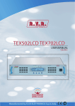
TEX30/50/100/150/300LCD
ELETTRONICA
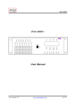
An LCD on the front panel and a push-button board provide for user interfacing
with the microprocessor control system, which offers the following features:
• Output power setup. • Operating frequency setup.
• Power output enable/disable.
• Power Good feature (User-selectable output power alarm threshold).
• Measurement and display of transmitter operating parameters.
• Communication with external devices such as programming or telemetry
systems via RS232 serial interface or I2C.
Four LEDs on the front panel provide the following status indications: ON, LOCK,
FOLDBACK and RF MUTE.
The exciters have an input for the external 24 Vcc supply. This auxiliary supply
source, that can be realized by the user with the help of rescue batteries, is
automatically used in case of AC voltage absence.
The exciter management firmware is based on a menu system. User has four
navigation buttons available to browse submenus: ESC , , , ed ENTER.
The rear panel features the mains input connectors, as well as audio input
connectors and RF output connector, telemetry connector, protection fuses and
two inputs for signals modulated onto subcarriers by suitable external coders, such
as RDS (Radio Data System) signals commonly used in Europe.
/ 32
Rev. 1.0 - 29/11/12
User Manual