1
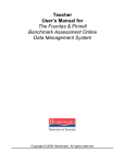
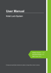
DG-1000M Standalone Proximity Reader
Operation User's Manual
Normal Operations
35
.5
70
Yellow LED is blinking, indicating stand-by mode. Depending on
unit's operational mode,operation will be as follows:
Codes + Proximity
When a card is presented, a beep indicates a successful read. If
card is found on unit, yellow LED begins blinking faster while
waiting for a code. All five digits need to be entered, one beep each,
before validation occurs. If longer than 5 seconds is taken
between digits, the mode will timeout back to normal mode. If code
matches expected code, green LED lights, and relay operates. If
card not found, or code does not match,
red LED lights for 2 seconds and 4 beeps are heard.
1
4
7
*
2
5
8
0
3
12
7.
5
6
9
#
Only Proximity
When a card is presented, a beep indicates a successful read. If
card is found on unit, green LED lights, and relay operates. If card
is not found, red LED lights and 4 beeps are heard. In this mode,
all keycodes will fail immediately.
Unit: mm
Codes or Proximity
If a card is presented, a beep indicates a successful read. If card is found on unit, green LED lights and relay
operates. If a code is entered, card reading will be inhibited until all 5 digits are entered. If the code is found
on unit, green LED lights, and relay operates. Card reading is re-enabled. If a card or code is not found, red
LED lights and 4 beeps are heard.
In normal operations, the " " functions as a clear key (it will beep only if digits have already been entered)
and the " " key is disabled.
Lockout mode: If 5 incorrect access attempts (card or code) are made in a row, the unit will lockout for 60
seconds (during which time, the keypad will not beep and no cards will read.). While in lockout mode,
programming mode is obviously inaccessible.
Forced Door Alarm: If the door is opened without being activated by a card\code or exit pushbutton, the
alarm relay is activated, the red LED lights and a beeping pattern starts (indicating forced door). This
condition persists until the door is closed again.
Door Left Open Alarm: If, after a valid operation (valid card/code/exit pushbutton), the door remains open
for longer than the alarm time delay, the alarm relay is operated, the red LED lights and a beeping pattern
starts (indicating door left open). This condition persists until the door is closed again.
Tamper Alarm: If the unit is opened, the alarm relay is operated, the red LED lights and a beeping pattern
starts. This condition persists until the unit is closed again.
Programming Operation
Entering/Exiting Programming Mode
Enter the master code twice. A beep for each digit will sound. If valid, yellow LED becomes
solid, and a longer beep confirms entry.
Note: The first time the master code is entered, the unit will reject the code. This is normal, and
intended to keep the master code secret. Depending on the operational mode of the unit, the delay
before the rejection will either be immediate (in a card only mode) or after the normal search time for
an unknown code (approximately 1.2s).
The second attempt will enter programming mode immediately.
" " will exit programming mode, as will 25 seconds of inactivity. A long beep confirms exit,
and the yellow LED returns to normal flashing.
Copyright Gianni Industries, Inc. All Rights Reserved.
P-MU-DG1000M
P u b l i s h : 2 0 0 5 . 11 . 1 0
Configuration Commands
Setting the Operational Mode
Enter " 0" . Then enter xx , where xx is "00" for Codes AND Proximity
"01" for Proximity only
"02" for Codes OR Proximity
Yellow will go off momentarily, and a long beep will sound.
If an incorrect value is entered, 4 beeps will sound.
Enter " " to exit programming mode, or proceed with another command.
Setting the Door Relay Time
Enter " 1" . Then enter xx, where xx is
"00" for latched operation
"01" for 1 second pulse
"99" for 99 second pulse
Yellow will go off momentarily, and a long beep will sound.
If an incorrect value is entered, 4 beeps will sound.
Enter " " to exit programming mode, or proceed with another command.
Note: Latched mode will toggle the relay between NC and NO connections.
Setting the Door Left Open Time
Enter " 2". Then enter xx, where xx is
"00" to disable Alarm function
"01" to set Alarm time to 10 seconds
"99" to set Alarm time to 990 seconds
Yellow will go off momentarily, and a long beep will sound.
If an incorrect value is entered, 4 beeps will sound.
Enter " " to exit programming mode, or proceed with another command.
Change Master Code
Enter " 3". Enter the new, 5 digit master code. If the code does not exist elsewhere
in the unit's memory, the yellow LED will go off momentarily, and a long beep will
sound. If it does exist, 4 beeps will be heard, and the master code will not be changed.
Enter " " to exit programming mode, or proceed with another command.
Card Commands
Adding cards
Enter the card position number, "000" to "999".
If red LED is on, the position is busy, and must either be cleared, or a new position selected.
To clear, press "
", which will light the green LED
To choose a different position, enter position number until the green LED goes on.
If/once the green LED is on, the position is vacant, and the card can be added.
Present the card to the reader. A beep will sound.
If yellow light blinks, enter a 5 digit code
If 4 beeps are heard, the code already exists, and cannot be used again. Enter a
different code, or " " to cancel.
If green LED turns off, addition was successful.
If 4 beeps are heard, the card already exists on the unit and cannot be added again.
Present a different card or " " to cancel.
To repeat, enter a new card position number, or " " to exit programming mode.
Notes: Irrespective of the MODE, a 5 digit code must be entered when adding a card, or the card will not be added. The Master code
cannot be used as an access code. Cards must be unique on the unit (ie. no duplicates) and codes must be unique on the unit
(ie. no duplicates)
Deleting cards
Enter the card position number, "000" to "999"
If red LED is on, this position is busy. Enter "
" to clear this position.
If\once green LED is on, this position is empty.
To repeat, enter a new card position number, or " " to exit programming mode
Copyright Gianni Industries, Inc. All Rights Reserved.
P-MU-DG1000M
P u b l i s h : 2 0 0 5 . 11 . 1 0
Beep and LED signals
Mode
Normal
LED Signals Programming
Reset
Normal
Beep Signals Programming
Reset
Signal
Yellow (flashing slowly)
Yellow (flashing quickly)
Green
Red
Yellow
Yellow (flashing slowly)
Green
Red
Green (flashing slowly)
Red (flashing slowly)
Red
1 beep
4 beep
1 long beep
4 beeps
1 beep
Power-on,stand-by
Waiting for code
Valid entry, door relay active
Warning, invalid card or code, tamper, alarm relay active
Programming mode active
Card read, awaiting code
Position available
Position occupied
About to reset Master Code
About to clear all memory
Card read, keypress
Invalid card
Card read, keypress
Data changed, entry/exit program mode
Input mistake, duplicate card, duplicate code
Signals steps in reset procedure
Default settings
Access Mode
Card Memory
Transaction Memory
Master codes
Door Left Open Time
Door Relay Time
Key timeout (fixed)
Awaiting code timeout (fixed)
Programming mode timeout
Card only (1)
Blank
Blank
12345 (5 digits)
Off (0)
5 seconds (5)
5 seconds
5 seconds
25 seconds
Resetting Master Code (and Memory)
To clear the Master Code only:
1. Close jumper ST1
2. Green LED flashes
3. Wait for one beep
4. Remove jumper
To clear the Master Code and ALL memory (card records and transactions)
1. Close jumper ST1
2. Green LED flashes
3. Wait for one beep
4. Red LED flashes
5. Wait for another beep
6. Remove jumper
(Memory will take approximately 30 seconds to clear, RED led will be lit during this process)
Copyright Gianni Industries, Inc. All Rights Reserved.
P-MU-DG1000M
P u b l i s h : 2 0 0 5 . 11 . 1 0
Connection Guide
The drawing below shows typical connections for the reader.
12V
DC or AC
-/~
+/~
STRIKE
V
To Alarm
DOOR
AC/DC
DOOR
ALARM
SWITCH
ALARM
NC
NC
NO
NO
JP1
JP2
RESET
JP3
Notes:
Power supply may be AC or DC. If AC power is used it is essential that connections to
the switches are made to the ~0V connection as shown in the drawing above.
The door strike must have a varistor across the door strike terminals to suppress the
back EMF of the strike - failure to do so will damage the relay contacts and electronic
components.
The door switch must open when the door opens. Door switch functionality will not be
enabled on the unit until it has detected the presence of a door switch.
The DOOR relay contacts can be set to Normally Open (NO) or Normally Closed (NC)
by setting the DOOR jumper JP1 to either NO or NC.
The Push Button to unlock the door must be Normally Open.
The ALARM relay contacts are voltage free and can be set to Normally Open (NO) or
Normally Closed (NC) by setting the ALARM jumper JP2 to either NO or NC
The RESET Jumper JP3 is used to reset the unit to the factory default settings and clear
memory.
The TAMPER switch will activate the ALARM relay, and is normally closed. Tamper
functionality will not be enabled on the unit until it has detected the cover to have been
closed. This allows the unit to be tested during installation without the back-plate being
present.
Copyright Gianni Industries, Inc. All Rights Reserved.
P-MU-DG1000M
P u b l i s h : 2 0 0 5 . 11 . 1 0