1
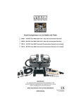
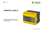
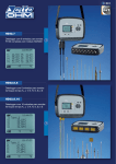
LP PHOT 01 LP PAR 01 LP RAD 01 LP UVA 01 LP UVB 01 LP UVC 01 $IBSBDUFSJ[JOH*MMVNJOBODF.FUFSTBOE-VNJOBODF.FUFSTwThe calibration is carried out by illuminating the probe with a standard illuminant A. TECHNICAL SPECIFICATIONS 5ZQJDBMTFOTJUJWJUZ 4QFDUSBMSBOHF $BMJCSBUJPOBDDVSBDZ f’1 (V(λ NBUDIFSSPS f2 DPTJOFSFTQPOTFEJSFDUJPOBMFSSPS f3MJOFBSJUZ f5GBUJHVF 0QFSBUJOHUFNQFSBUVSF 0VUQVUJNQFEBODF N7LMVY 7λ) ¡$ Lû 38 Ø 30 Typical spectral response LP PHOT 01 1 LP PHOT 01 0.9 0.8 Relative spectral response 0.7 0.6 0.5 0.4 0.3 0.2 0.1 0 380 430 480 530 580 630 680 730 780 830 LP RAD 01: The LP RAD 01 probe measures irradiance (W/m2 ) defined as the ratio between the radiant flux (W) passing through a surface and the surface area (m2 JOUIF7*4/*3ONON spectral range. These particular features apply to an instrument suitable for measurements in visible and near infrared fields. Probe calibration is carried out by using 577 and 579 nm lines of a Xe-Hg lamp, filtered through a special interferential filter. LP PHOT 01, LP RAD 01, LP PAR 01, LP UVA 01, LP UVB 01, LP UVC 01 PHOTOMETRIC/RADIOMETRIC PROBES WITH mV SIGNAL OUTPUT. LP PHOT 01S WITH RS485 MODBUS-RTU OUTPUT The probes of the series LP…01 allow measurement of photometric and radiometric quantities such as illuminance (lux), irradiance (W/m2 BDSPTT7*4/*367"67#67$TQFDUSBMSFHJPOT the number of photons per time unit and area in the PAR region (400nm ... 700nm). *OQSPCFT-1yUIFSFJTOPOFFEGPSFYUFSOBMQPXFSTVQQMZ0VUQVUTJHOBMJON7JTHJWFO through a resistor shunting the photodiode ends. Photocurrent generated by the photodiode when hit by light, is converted to a potential difference, which is read by a voltmeter. Once the DDP (Potential Difference) has been read, the measured value can be calculated through the calibration factor. All probes are individually calibrated and the calibration factor is shown both on the probe housing and on the user manual and is specific to that probe. -1yQSPCFTBSFFRVJQQFEXJUIDPTJOFDPSSFDUFEEJGGVTFS*OQSPCFTGPS67NFBTVSFNFOUT the diffuser is made of sanded quartz, for the other probes, the diffuser is commonly made of acrylic material or teflon® (LP PHOT 01). LP ... 01 probes are suitable for indoor applications which requires the constant monitoring of the quantities specified. The output signal can be amplified or converted into a 4...20mA or 0...10Vdc signal by using a converter of the series )%53N" BOE)%537ED GPS%*/SBJMBUUBDINFOUPSUIFXBMMNPVOUJOH types HD978TR5 (4...20mA) and HD978TR6 (0...10Vdc). Installing the probes Once the installation place has been decided, the connections between the probe and the voltmeter should be provided; the voltmeter should have proper scales of measurement. The connection diagram of the probe output cables is shown in the user manual. For measurements in weather and agriculture stations or in nursery-gardening systems, the probe reference plane should be mounted parallel to the ground; in this case, the probe shall be mounted on a LP BL (optional) support provided with bubble level. Probe description LP PHOT 01: The LP PHOT 01 probe measures illuminance (lux) defined as the ratio between the luminous flux (lumen) passing through a surface and the surface area (m2). The spectral response curve of a photometric probe is equal to the one of the human eye, known as standard photopic curve V(λ). The difference in spectral response between LP PHOT 01 and the standard photopic curve V(λ) is calculated by means of the error f1’. The calibration of the probe is performed by comparing it to a luxmeter calibrated by a Primary Metrological *OTUJUVUF "MM DBMJCSBUJPO QSPDFEVSFT GPMMPX UIF $*& QVCMJDBUJPO /P i.FUIPE PG TECHNICAL SPECIFICATIONS 5ZQJDBMTFOTJUJWJUZ .FBTVSJOHSBOHF 4QFDUSBMSBOHF $BMJCSBUJPOBDDVSBDZ f2 DPTJOFSFTQPOTFEJSFDUJPOBMFSSPS 0QFSBUJOHUFNQFSBUVSF 0VUQVUJNQFEBODF ç7ç8DN2) N8DN2 ≈400nm...≈1050nm ¡$ Lû 38 Typical spectral response LP RAD 01 Ø 30 LP RAD 01 1 ,0 0 ,8 Relative spectral response LP PHOT 01S 0 ,6 0 ,4 0 ,2 0 ,0 350 450 550 650 750 850 950 1050 h (n m ) LP UVA 01: The LP UVA 01 probe measures irradiance (W/m2 ) defined as the ratio between the radiant flux (W) passing through a surface and the surface area (m2) in the UVA (315 nm ... 400 nm) spectral range. Thanks to a new type of photodiode, LP UVA 01 is blind to visible and infrared light. Probe calibration is carried out by using a 365 nm line of a Xe-Hg lamp, filtered through a special interferential filter. Measurement is carried out by comparison with the primary standards, assigned to Delta Ohm Metrological Laboratory. 5IJTQSPCFDBOCFVTFEJOBMMQSPDFTTFTXIFSFVMUSBWJPMFUMBNQFNJTTJPOOFFETUPCFNPOJUPSFE resins and adhesives polymerization, as well as tanning lamps. LG-17 Light h (nm) TECHNICAL SPECIFICATIONS 5ZQJDBMTFOTJUJWJUZ ç7ç8DN2) .FBTVSJOHSBOHF N8DN2 5ZQJDBMTQFDUSBMSBOHF QFBLBU≈360 nm and FWHM 60 nm $BMJCSBUJPOBDDVSBDZ 8PSLJOHUFNQFSBUVSF ¡$ 0VUQVUJNQFEBODF Lû Typical spectral response LP UVC 01 1 LP UVC 01 38 Relative spectral response 0.8 Typical spectral response LP UVA 01 1 0.9 Ø 30 LP UVA 01 0.9 0.8 0.6 0.5 0.4 0.3 0.2 0.7 Relative spectral response 0.7 0.1 0.6 0 200 210 220 230 24 0 0.5 250 260 270 280 290 300 h ( nm ) 0.4 LP PAR 01: The LP PAR 01 probe measures the ratio between the number of photons that strike a surface in one second, in the 400nm ... 700nm spectral range and the surface area (m2). This quantity JTEFmOFEBT1"31IPUPTZOUIFUJDBMMZ"DUJWF3BEJBUJPO The probe calibration is carried out by using an halogen lamp, with a known spectral irradiance in a specific spectral range. Temperature slightly affects the probe spectral response. The diffuser and the probe particular structure, allow the response to the variation of the light incidence angle on the diffuser, to be cosine corrected. 0.3 0.2 0.1 0 280 300 320 340 360 380 400 420 h ( nm ) LP UVB 01: The LP UVB 01 probe measures irradiance (W/m2 ) defined as the ratio between the radiant flux (W) passing through a surface and the surface area (m2) in the UVB (280 nm ...315 nm) spectral range. Thanks to a new type of photodiode, LP UVB 01 is blind to visible and infrared light. Probe calibration is carried out by using a 313 nm line of a Xe-Hg lamp, filtered through a special interferential filter. Measurement is carried out by comparison with the primary standards, assigned to Delta Ohm Metrological Laboratory. TECHNICAL SPECIFICATIONS 5ZQJDBMTFOTJUJWJUZ ç7ç8DN2) .FBTVSJOHSBOHF N8DN2 5ZQJDBMTQFDUSBMSBOHF QFBLBU≈ 305 nm and FWHM 31 nm $BMJCSBUJPOBDDVSBDZ 8PSLJOHUFNQFSBUVSF ¡$ 0VUQVUJNQFEBODF Lû TECHNICAL SPECIFICATIONS 5ZQJDBMTFOTJUJWJUZ .FBTVSJOHSBOHF 5ZQJDBMTQFDUSBMSBOHF $BMJCSBUJPOBDDVSBDZ f2 DPTJOFSFTQPOTFEJSFDUJPOBMFSSPS 0QFSBUJOHUFNQFSBUVSF 0VUQVUJNQFEBODF ç7çNPMrN-2s-1) çNPMrN-2s-1) ONON ¡$ Lû 38 Ø 30 Typical spectral response LP PAR 01 0,7 38 PAR Relative spectral response 0,6 Typical spectral response LP UVB 01 Ø 30 1 LP UVB 01 0.9 0,5 0,4 0,3 0,2 0.8 Relative spectral response 0,1 0.7 0 350 0.6 400 450 500 550 600 650 700 750 800 850 h (nm) 0.5 0.4 0.3 0.2 0.1 0 25 0 260 270 280 290 300 310 320 330 340 350 h ( nm ) LP UVC 01: The LP UVC 01 probe measures irradiance (W/m2) defined as the ratio between the radiant flux (W) passing through a surface and the surface area (m2) in the UVC (200nm ...280nm) spectral range. Thanks to a new type of photodiode, LP UVC 01 is blind to visible and infrared light. The probe calibration is carried out by measuring irradiance coming from an Hg lamp at 254nm. TECHNICAL SPECIFICATIONS 5ZQJDBMTFOTJUJWJUZ .FBTVSJOHSBOHF 5ZQJDBMTQFDUSBMSBOHF $BMJCSBUJPOBDDVSBDZ 8PSLJOHUFNQFSBUVSF 0VUQVUJNQFEBODF ç7ç8DN2) N8DN2 QFBLBUBOE'8).ON ¡$ Lû 38 Ø 30 LG-18 Ordering codes: LP PHOT 01:1IPUPNFUSJDQSPCFGPSNFBTVSJOH*--6.*/"/$&$*&QIPUPQJDmMUFSEJGGVTFSGPS correction according to the cosine law. mV per klux output, cable 5m long. LP RAD 01:3BEJPNFUSJDQSPCFGPSNFBTVSJOH*33"%*"/$&EJGGVTFSGPSDPSSFDUJPOBDDPSEJOHUP the cosine law. mV per mW/cm2 output, cable 5m long. LP PAR 01: Radiometric probe for measuring PHOTONS FLUX in the range of PAR (Photosynthetically Active Radiation). Cosine correction. mV per μmol/m2s output, cable 5m long. LP UVA 01: 3BEJPNFUSJD QSPCF GPS NFBTVSJOH *33"%*"/$& JO UIF 67" yON ç7 μWcm-2 output, cable 5m long. LP UVB 01: 3BEJPNFUSJD QSPCF GPS NFBTVSJOH *33"%*"/$& JO UIF 67# yON ç7 μWcm-2 output, cable 5m long. LP UVC 01: 3BEJPNFUSJD QSPCF GPS NFBTVSJOH *33"%*"/$& JO UIF 67$ yON ç7 μWcm-2 output, cable 5m long. LP BL: Base with levelling device. On request for assembly with the probes at the time of placing the order. HD978TR3: Configurable signal converter amplifier with 4...20mA (20...4mA) output. *OQVUNFBTVSJOHSBOHFN7%FGBVMUTFUUJOHN7'PS%*/SBJMBUUBDINFOU Minimum measuring range 2mV. HD978TR4: Configurable signal converter amplifier with 0...10Vdc (10...0Vdc) output. *OQVUNFBTVSJOHSBOHFN7%FGBVMUTFUUJOHN7'PS%*/SBJMBUUBDINFOU Minimum measuring range 2mV. HD978TR5: Configurable signal converter amplifier with 4...20mA (20...4mA) output. *OQVUNFBTVSJOHSBOHFN7%FGBVMUTFUUJOHN7 Minimum measuring range 2mV. HD978TR6: Configurable signal converter amplifier with 0...10Vdc (10...0Vdc) output. *OQVUNFBTVSJOHSBOHFN7%FGBVMUTFUUJOHN7 Minimum measuring range 2mV. LP PHOT 01S Transmitter with MODBUS-RTU RS485 output for the probe LP PHOT 01 The transmitter LP PHOT 01S converts the mV analog signal generated by the illumination probe LP PHOT 01 into a digital signal suitable to be transmitted over a serial line RS485 with MODBUS-RTU protocol. All connections are made via screw terminals accessible by removing the top cover of the transmitter. The container is designed for wall mounting. Technical specifications -PXSBOHFyMVYEFGBVMU )JHI3BOHFyMVY 1 lux (low range) / 10 lux (high range) RS485 (1 Unit Load) with MODBUS-RTU protocol, non isolated 5…30 Vdc 80 x 84 x 44 mm *1 y¡$y63XJUIPVUDPOEFOTBUJPO y¡$ Measuring range of the probe LP PHOT 01 Resolution Output Power supply Housing dimensions Protection degree Working Temperature / %RH Storage temperature Setting the RS485 communication parameters of the transmitter Before connecting the transmitter to the RS485 network, assign an address and set the communication parameters, if different from those preset by the factory. The parameter setting is done by connecting the transmitter to the PC via optional RS48, with JOUFHSBUFEDPOWFSUFS3464#*OPSEFSUPVTFUIFDBCMFUIF64#ESJWFSTTIPVMECFJOTUBMMFE on your PC. Alternatively, instead of the cable RS48, it is possible to use a generic RS485/ RS232 or RS485/USB converter. Command Response Description Sets transmission mode RS485 n=0 ⇒ 8-N-1 (8 data bit, no parity, 1 stop bit) n=1 ⇒ 8-N-2 (8 data bit, no parity, 2 stop bit) n=2 ⇒&EBUBCJUOPQBSJUZTUPQCJU CMPn &| n=3 ⇒&EBUBCJUOPQBSJUZTUPQCJU n=4 ⇒ 8-O-1 (8 data bit, no parity, 1 stop bit) n=5 ⇒ 8-O-2 (8 data bit, no parity, 2 stop bit) Preset to 2 ⇒& Sets receiving mode after RS485 transmission n=0 ⇒ Violates the protocol and goes in Rx mode right after Tx CMWn &| n=1 ⇒ Respects the protocol and waits 3.5 characters after Tx Preset on 1 ⇒ Respects the protocol *UJTQPTTJCMFUPDIFDLUIFQBSBNFUFSTFUUJOHTCZTFOEJOHUIFGPMMPXJOHDPNNBOET Command RMA Response Address RMB Baud Rate RMP Tx Mode (0,1,2,3,4,5) RMW Rx Mode (0,1) Description Reads the RS485 address Reads RS485 Baud Rate 0 ⇒ 9600 1 ⇒ 19200 Reads RS485 transmission mode 0 ⇒ 8-N-1 1 ⇒ 8-N-2 2 ⇒& 3 ⇒& 4 ⇒ 8-O-1 5 ⇒ 8-O-2 Reads receiving mode after RS485 transmission 0 ⇒ Violates the protocol and goes in Rx mode right after Tx 1 ⇒ Respects the protocol and waits 3.5 characters after Tx LP PHOT 01S 5 6 7 8 LP PHOT 01S INPUT mV+ mV- SHIELD Connection diagram for the operating mode 1 2 3 4 PWR+ B/+ A/- PWR- 5 6 7 8 mV+ mV- SHIELD PWR+ B/+ A/- PWR- Probe cable INPUT OUTPUT 1 2 3 4 1 2 3 4 LP PHOT 01 B/+ 1 2 3 4 A/- A/- PWR+ B/+ A/- PWR- B/+ RS485/USB RS485/RS232 Power supply 5...30 Vdc PWRPWR+ Power supply 5…30 Vdc Notes on the USB driver installation: With operating systems Windows 7 and Windows 8, before installing the driver, restart the PC by disabling the driver signing request. During the restart, press F8 to display the menu “Advanced Boot Options”, then select the “Disable Driver Signature Enforcement”. V+ GND Procedure for setting the parameters. 1. The transmitter should be powered off. 2. Start a program of serial communication standards, such as Hyperterminal. set the number of the COM port to which the transmitter should be connected, set the Baud Rate to 57600 BOEUIFDPNNVOJDBUJPOQBSBNFUFSTBTGPMMPXT %BUBCJUT 1BSJUZ/POF 4UPQCJUT 3. Power the transmitter on and wait for the reception of the character &, then send (within 10s from the instant the transmitter is powered on), the @ command and press the enter key. Note *G UIF USBOTNJUUFS EPFT OPU SFDFJWF UIF @ command within 10 seconds since when QPXFSFEJUBVUPNBUJDBMMZTXJUDIFTUIF34.0%#64PO*OUIJTDBTFJUJTOFDFTTBSZUP remove and restore power to the transmitter. 4. Send the command CAL USER ON. Note5IFDPNNBOE$"-64&30/UVSOTPGGBGUFSNJOVUFTPGJOBDUJWJUZ 5. Send the serial commands reported in the following table to set the parameters of RS485 .0%#64 Command Response CMAnnn &| CMBn &| Description Set address RS485 a nnn Between 1 and 247 Preset to 1 Set Baud Rate RS485 n=0 ⇒ 9600 n=1 ⇒ 19200 Preset to 1 ⇒ 19200 B/+ A/- Other sensors with RS485 output Termination Termination +5Vdc 390 With a 64-bit operating system, even after installation, the request of the driver signing must be disabled every time the PC is restarted. Lmax = 1200m 3/&GDWDORJJHURU RS485/USB or RS485/RS232 FRQYHUWHUIRU3& B/+ 220 A/220 Shield Terminal 1 2 3 4 5 6 7 8 B/+ A/- Shield Symbol PWR+ B/+ A/PWRmV+ mV4)*&-% Light 5 6 7 8 PWRPWR+ INPUT OUTPUT mV+ mV- SHIELD PWR+ B/+ A/- PWR- 390 GND Function Positive Power Supply RS485 B/+ RS485 A/Negative Power Supply Positive input signal in mV Negative input signal in mV Probe cable shield Grounding *OPSEFSUPHFUUIFNBYJNVNBDDVSBDZJUJTSFDPNNFOEFEOPUUPFYUFOEUIFTIJFMEFEDBCMF UIBUDBNFXJUIUIF-11)05*UJTBMTPSFDPNNFOEFEOPUUPQBTTUIFXJSJOHJOUIFWJDJOJUZ of power cables (motors, induction ovens, inverters, etc…). *O 34 DPOOFDUJPO UIF JOTUSVNFOUT BSF DPOOFDUFE WJB B TIJFMEFE UXJTUFE QBJS DBCMF GPS signals and a third wire for grounding. At the two ends of the network must present the line terminations. To polarize the line during periods of non-transmission, use the resistors connected among the signal lines and the power supply. The maximum number of devices connected to the line (Bus) RS485 depends on the load characteristics of the devices to be connected. The RS485 standard requires that the total load does not exceed 32 unit loads (Unit Loads). The load of a transmitter LP PHOT 01S is equal to 1 unit load. *GUIFUPUBMMPBEJTHSFBUFSUIBOVOJUMPBETEJWJEFUIFOFUXPSLJOUPTFHNFOUTBOEUIFOQVU in a segment and the next a signal repeater. The beginning and end of each segment must be applied for line termination. LG-19 Operating mode The transmitter enters the RS485 MODBUS-RTU mode after 10 seconds after turning on. During the first 10 seconds after turning on, the unit does not respond to any requests from the “master” MODBUS unit. After 10 seconds, it is possible to send requests to the transmitter MODBUS At the end of the settings, turn off and on the transmitter to activate the operating mode RS485 MODBUS-RTU. Dimensions Reading the measurements by using the MODBUS-RTU protocol *U JT QPTTJCMF UP SFBE UIF NFBTVSFE WBMVFT CZ UIF USBOTNJUUFS CZ VTJOH DPEF GVODUJPO I 3FBE*OQVU3FHJTUFST 5IFGPMMPXJOHUBCMFMJTUTUIFJOGPSNBUJPOBWBJMBCMFXJUIUIFBQQSPQSJBUF SFHJTUFSBEESFTT Address 2 3 4 5 Quantity *MMVNJOBODFJOMVYMPXSBOHF PSMVYIJHISBOHF Status register bit 0 = 1 ⇒ measure illuminance in error bit 2 = 1 ⇒ error in the configuration data bit 3 = 1 ⇒ error in the program memory Average illuminance in lux (low range) or lux/10 (high range) The average of the last 4 measurements Value of the input signal in μV (low range) or μV/10 (high range) Format *OUFHFS *OUFHFS *OUFHFS *OUFHFS Setting the sensitivity of the probe and the measurement range The measuring range preset in the transmitter is 0…10,000 lux (low range), normally TVJUBCMFGPSJOEPPSNFBTVSFNFOUT*GJUIBTUPCFIJHIFSGPSFYBNQMFJOUIFDBTFPGPVUEPPS measurements, it can be set to 0...200,000 lux (high range). The two ranges meet different SFTPMVUJPOTMVYGPSUIFMPXSBOHFMVYGPSUIFIJHISBOHF The setting of the value of the probe sensitivity is required in case of replacement of the probe connected to the transmitter with a new probe with different sensitivity. *OPSEFSUPTFUUIFTFOTJUJWJUZPGUIFQSPCFBOEUIFNFBTVSFNFOUSBOHFQSPDFFEBTGPMMPXT 1. Start when the transmitter is not powered. 2. Connect the transmitter to your PC via optional RS48 cable. 3. Start a standard serial communication program, such as Hyperterminal. Set the number of the COM port to which the transmitter has to be connected, set the Baud Rate to 57600 and DPNNVOJDBUJPOQBSBNFUFSTBTGPMMPXT %BUB#JUT 1BSJUZ/POF 4UPQCJU 4. Power the transmitter on and wait for the reception of the character &, then send (within 10 s from the instant the transmitter is powered on) the @ command and press the enter key. /PUF*GUIFUSBOTNJUUFSEPFTOPUSFDFJWFUIF@ command within 10 seconds since when QPXFSFEJUBVUPNBUJDBMMZTXJUDIFTUPUIF34.0%#64*OUIJTDBTFJUJTOFDFTTBSZUP remove and restore the power to the transmitter. 5. Send the command CAL START. /PUF5IFDPNNBOE$"-45"35UVSOTPGGBGUFSNJOVUFTPGJOBDUJWJUZ 4FOEUIFGPMMPXJOHTFSJBMDPNNBOET Command Response Description CLSnnn &| Sets the sensitivity of the probe to the value nnn in μV/klux & &| Sets a low range (0…10.000 lux, resolution 1 lux) 02D &| Sets a high range (0…200.000 lux, resolution 10 lux) 7. *UJTQPTTJCMFUPDIFDLUIFTFUUJOHPGUIFTFOTJUJWJUZPGUIFQSPCFBOEPGUIFNFBTVSFNFOU SBOHFCZTFOEJOHUIFGPMMPXJOHDPNNBOET Command Response Description RLS & nnn| RO hh| Reads the set sensitivity in μV/klux 3FBETUIFDPOmHVSBUJPOCJUF bit 2 = 0 ⇒ high range (0…200.000 lux, resolution 10 lux) bit 2 = 1 ⇒ low range (0…10.000 lux, resolution 1 lux) the bit 2 is the third bit from the right of the configuration byte NoteUIFSFBEJOHPGUIFTFUUJOHTXJUIUIFDPOUSPMTBOE3-4BOE30EPFTOPUSFRVJSFTFOEJOH the command CAL START. LG-20 Ordering codes LP PHOT 01S: Transmitter with RS485 MODBUS-RTU for the illumination probe LP PHOT 01. .FBTVSJOHSBOHFMVYXJUISFTPMVUJPOMVYPSMVYXJUISFTPMVUJPO 10 lux. Connections with screw terminals. Housing for wall mounting. Power supply 7ED&RVJQQFEXJUIJMMVNJOBUJPOQSPCF-11)05 RS48:$POOFDUJOHDBCMFUP1$GPSUIFDPOmHVSBUJPOPGUIF.0%#64QBSBNFUFST&RVJQQFEXJUI integrated converter RS485/USB. Free leads from the instrument, USB type A connector on the PC side.