1
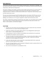
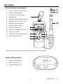
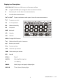
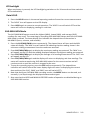
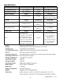
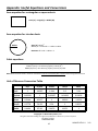
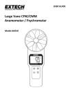
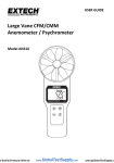
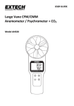
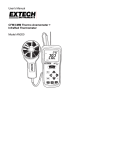
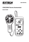
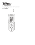
USER GUIDE Mini‐Vane CMM/CFM Anemometer/Psychrometer + Datalogger Model AN340 Introduction Thank you for selecting the Extech AN340 CMM/CFM Anemometer Psychrometer Datalogger. This instrument measures Air Velocity, Air Flow (volume), Air Temperature, Relative Humidity, Wet Bulb Temperature, and Dew Point Temperature. The meter’s compact mini impeller is perfect for duct airflow measurements. The sensor probe has an 18mm (0.7”) diameter and a 1M (39”) telescoping probe wand with a marked scale. Duct temperature does not affect the airflow measurement results. Temperature and humidity sensors are built into the vane sensor. The user can manually store and recall 99 readings directly on the meter’s LCD. The user can also automatically log up to 12,000 readings with date and time stamp and selectable sampling rate. Readings are transferred to a PC using the supplied PC software and USB connector cable. This meter is shipped fully tested and calibrated and, with proper use, will provide years of reliable service. Please visit our website (www.extech.com) to check for the latest version of this User Guide, Product Updates, and Customer Support. CAUTIONS Improper use of this meter can cause damage to the meter and personal injury. Read and understand this user manual before operating the meter. Inspect the condition of the probe and the meter for any damage before operating the meter. Repair or replace damage before use. If the equipment is used in a manner not specified by the manufacturer, the protection provided by the equipment may be impaired. This device should not be made available to children. It contains hazardous objects as well as small parts that can be accidentally swallowed. The meter’s batteries and packing materials can also be dangerous to children. In the event that the meter is to be unused for an extended period of time, remove the batteries to protect against battery leakage. Expired or damaged batteries can be hazardous if allowed to come in contact with skin. Use suitable hand protection in such cases. Do not short circuit batteries or put batteries in fire. 2 AN340-EU-EN V1.1 3/13 Description Meter and Sensor Description 1. Sensor connection to the meter 2. Main LCD display digits 3. Lower line LCD display digits 4. MODE button 5. AVG‐MAX‐MIN and ENTER button 6. POWER ON‐OFF and SET button 7. HOLD and up arrow button 8. MEM and RECALL button 9. START and ESC button 10. LW‐D‐A and down arrow button 11. Mini‐Vane impeller 12. Temperature and humidity sensors 13. Telescoping sensor arm Note: Battery compartment (not shown) is located on rear of instrument Meter Top Description 1. Sensor connection jack 2. USB PC interface jack 3. AC power adaptor jack 3 AN340-EU-EN V1.1 3/13 Keypad Description POWER ON‐OFF and SET button Press momentarily to power meter ON or OFF. Press and hold for two (2) seconds to enter the SETUP mode. MODE button Momentary press to step through the available modes: air velocity, air volume, air temperature, relative humidity, wet bulb temperature, dew point temperature. AVERAGE, MAXIMUM, MINIMUM, and ENTER button Press to view average/minimum/maximum readings. Also used to confirm (enter) a selection while programming. START, ESC button In the normal operating mode, press and hold for two (2) seconds to start or stop the automatic datalogger. Also, press to exit (escape) AVG/MIN/MAX, RECALL, and SETUP modes. HOLD, UP ARROW button In the normal mode, press to freeze/un‐freeze the displayed reading. It is also used to move UP in a menu list. LW‐D‐A (LENGTH/WIDTH‐DIAMETER‐AREA) button In the Air Volume mode, press this button to begin programming the AREA value for the duct under test. This button is also used to move DOWN a menu list. MEM‐RECALL button In the normal mode of operation, press this button to manually record a reading into the meter’s 99 location memory. Press and hold for two (2) seconds to recall and review the manually recorded data one reading at a time. and With the meter OFF, press and hold these two buttons to disable the sleep mode. Sleep mode switches the meter off automatically after a twenty (20) minute period of inactivity. 4 AN340-EU-EN V1.1 3/13 Display Icon Description MAX‐MIN‐AVG Maximum, Minimum, and Average readings LW Length and Width (for rectangular duct area measurements) D Diameter (for circular duct area measurements) A Area for duct measurements 2 2 Cm and inch o Square centimeters and square inches for area measurements C/F Temperature units TA Air Temperature RH Relative Humidity DP Dew point WBT Wet bulb VEL Velocity VOL Volume HOLD Display HOLD feature %rh Relative Humidity unit of measure m/s Meters per second ft/m Feet per minute CFM Cubic feet per minute CMM Cubic meters per minute REC Record RECALL Recall AM/PM Morning/Evening time B Low Battery 8888.8 Main (larger and upper) display digits 88‐88‐88 Timer (lower) display digits 5 AN340-EU-EN V1.1 3/13 Operation Power ON‐OFF 1. Switch the meter ON by pressing the power button momentarily. 2. Press again to switch the meter OFF. 3. If the meter does not switch ON, check that the meter has six (6) fresh AAA batteries installed in the rear battery compartment. Refer to the battery installation section for details. 4. The meter can also be powered using the 9V AC power adaptor. The power adaptor connects to the top of the meter using the jack as shown in the Description section of this guide. Sleep mode The meter will automatically enter the sleep mode (switch off) after twenty (20) minutes of inactivity. To disable this feature: with the meter OFF, press and hold the SET and HOLD buttons for two (2) seconds. The LCD will display 'n' as it switches ON. Now the sleep mode is disabled and the user must press the power button momentarily to switch the meter OFF. Measurements 1. Connect the sensor to the jack at the top of the meter as shown in the Description section. Then sensor and jack are keyed to ensure proper connection. The sensor diameter is 18mm (0.7”) and the telescoping wand extends 1m (39”). 2. With the meter switched ON, use the MODE button to advance from one measurement type to the next (air velocity, air flow or volume, air temperature, relative humidity, wet bulb temperature, and dew point temperature). Note that for air volume measurements the user must first enter the area value for the duct under test before accurate readings can be made. Refer to the AREA section of this guide for programming details and to the Appendix for additional information on area measurements, calculations, and unit conversions. 3. When measuring, air must enter the vane on the side of the sensor with the printed words AIR IN. The sensor wand can be extended using its telescoping capability up to 1m (39”). 4. The measurement is indicated on the upper display digits along with the currently selected unit of measure. To change the unit of measure, refer to the SETUP mode section. The lower display line shows the real time clock, alternating time and date information. 5. The air temperature and relative humidity sensors are located in the slotted opening on the sensor wand below the impeller. 6. Air velocity readings are indicated in meters per second (m/s) or feet per minute (fpm). Temperature readings (air, dew point, or wet bulb) are indicated in °C/°F. Relative Humidity is indicated in %. Air flow (volume) is indicated in CFM (cubic feet per minute) or CMM (cubic meters per minute). 7. To measure relative humidity using an offset reference value, please access the Setup mode and input the offset value as described in the Setup mode section. The LCD will display the measured value minus the offset value once the offset is programmed in the Setup mode. 6 AN340-EU-EN V1.1 3/13 LCD backlight When any button is pressed, the LCD backlighting switches on for 10 seconds and then switches OFF automatically. Data HOLD 1. Press the HOLD button in the normal operating mode to freeze the current measurement. 2. The ‘HOLD’ icon will appear on the LCD display. 3. Press HOLD again to return to normal operation. The ‘HOLD’ icon will switch OFF and the meter will return to displaying readings in real time. AVG‐MAX‐MIN Mode The AVG‐MAX‐MIN feature records the highest (MAX), lowest (MIN), and average (AVG) readings for easy recall. The meter begins recording AVG‐MAX‐MIN values when the AVG‐MAX‐ MIN mode is started. The lower display line indicates the elapsed time of the session in HH:MM:SS (hours, minutes, and seconds) 1. Press the AVG/MAX/MIN button momentarily. The elapsed timer will start and the MIN value will display. The ‘MIN’ icon will switch ON indicating that the reading shown is the minimum reading encountered since the mode was accessed. 2. Press AVG/MAX/MIN again to display the maximum reading encountered. The ‘MAX’ icon will appear on the LCD and the reading displayed indicates the highest reading encountered. 3. Press AVG/MAX/MIN again to display the average of all reading encountered. The ‘AVG’ icon will appear on the LCD. 4. Press AVG/MAX/MIN again and the display will return to displaying real time readings. The meter will continue monitoring AVG‐MAX‐MIN values for the current session and will continue to do so until the session is stopped by the user. 5. To stop the recording session, press the ESC button momentarily. The elapsed time indication will switch off and the lower display digits will return to displaying the current date and time (the ‘AVG, ‘MAX’, and ‘MIN’ icons will switch OFF). 6. Note that during an AVG‐MAX‐MIN recording session, the MODE button can be used, as it normally is, to step through the displayed measurement types. 7. Also note that the HOLD and MANUAL RECORD modes of operation are disabled during an AVG‐MAX‐MIN session. 7 AN340-EU-EN V1.1 3/13 99 Reading Manual Datalogger The meter can record up to 99 readings manually for on‐screen recall. 1. Press the MEM‐RECALL button momentarily to record one reading. The display will flash briefly and the reading will be stored in the memory location indicated on the display (from location 1 up to location 99). Note that all readings types are stored not only the reading type currently displayed. For example, if air velocity readings are displayed, wet bub and dew point temperatures will also be recorded. Date/time stamp of the recording is also recorded. 2. To review the readings, press and hold the MEM‐RECALL button for two (2) seconds; the ‘RECALL’ icon will switch ON. Now use the up and down arrow buttons to scroll the stored readings. The memory location will appear first in the main display area followed by the reading. The time stamp for the recording is shown on the lower, timer digits. Use the MODE button to step through the other measurement types. 3. Press the ESC button momentarily to exit the MEM‐RECALL mode. 4. The readings will remain in memory until overwritten or erased by the user. To erase readings, follow the steps provided in the SETUP mode section of this guide. 12,000 Reading Automatic Datalogger and PC Interface The 12,000 reading datalogger can record readings at a rate selected by the used automatically. Use the SETUP mode to select the sampling rate (from 1 second up to 4 hours 59 minutes 59 seconds). Logged readings must be downloaded to a PC using the supplied software program in order for the readings to be read and analyzed. 1. Press and hold the START‐ESC button for two (2) seconds to start the datalogger. Readings will be logged at the sampling rate selected by the user in the SETUP mode. The ‘REC’ icon will flash while the meter is automatically logging. 2. All parameters (velocity, volume, dew point, wet bulb, and humidity) will be logged regardless of which parameter is displayed. 3. While logging, the upper display digits indicate the real time readings; the lower display shows the real time clock. 4. To stop the datalogger press and hold the START‐ESC button again for two (2) seconds. 5. Important Note: If the datalogger is started again before the data from the previous session is downloaded to a PC, all data from the previous session will be overwritten (erased). 6. During the datalogging session, the MODE button can be used, as it normally is, to switch the measurement parameter (velocity, volume, dew point, etc.). 7. AVG‐MAX‐MIN, manual logging, and HOLD modes are disabled while the meter is datalogging. 8. Install and run the supplied datalogging software program to transfer the logged readings to the PC. The meter connects to the PC via a USB cable (meter’s USB jack is located at the top of the meter as shown in the Description section). Read the software help guide available in the software program for full software operating instructions. 8 AN340-EU-EN V1.1 3/13 AREA programming for Air Flow (Volume) CMM/CFM Measurements To accurately measure the volume of air flow in a duct, the area of the duct must first be measured and the result entered in the meter via the button press sequences described below. Refer to the Appendix for more information on area measurements, calculations, and unit conversions. Area 2 2 measurements are entered as square centimeters or square inches (cm or inch ). First decide the method for programming the area information into the meter and then proceed. The three methods are: a. L x W: Enter the duct’s Length & Width measurement values in centimeters or inches (rectangular ducts); the meter then calculates the area in square centimeters or square inches (cm2 or inch2). b. D: Enter the duct’s Diameter value in centimeters or inches (for round ducts); the meter 2 2 calculates the area automatically in square centimeters or square inches (cm or inch ). 2 2 c. A: Enter the area value directly in square centimeters or square inches (cm or inch ). See the Appendix for tips on area measurements, calculations, and unit conversions. Important Note: Area measurements must be entered in centimeters or inches. If measurements are made in meters or feet please convert to centimeters or inches. See the Appendix for more information. From the normal operating mode, use the MODE button to scroll to the Air Volume mode. Use the LW‐D‐A button to select the method: LW (LENGTH x WIDTH for rectangular ducts), D (DIAMETER for circular ducts), or A (AREA: if the area value is known). The display icons L, D, and A inform the user as to which mode is selected. LENGTH x WIDTH (Area) Mode When the ‘L’ is shown at the top of the LCD, the meter is ready to accept a rectangular duct’s Length measurement in centimeters or inches. Use the button ONLY to change the value of the flashing digit (pressing the down arrow will cause the screen to change from Length to Diameter). Use the ENTER button to move from digit to digit. When finished entering the length, and with the right‐most digit flashing, press the ENTER button to move to the Width (W) screen. When the ‘W’ is shown at the top of the LCD, the meter is ready to accept the Width measurement in centimeters or inches. Use the button ONLY to change the value of the flashing digit (pressing the down arrow will cause the screen to change to Diameter mode). Use the ENTER button to move from digit to digit. When finished entering the width, and with the right‐most digit flashing, press the ENTER button to return to the main operating mode. The meter automatically calculates the area of the duct and, when volume measurements are taken, the LCD will show accurate air volume (flow) in CMM/CFM units. 9 AN340-EU-EN V1.1 3/13 DIAMETER (Area) Mode When the ‘D’ is shown at the top of the LCD, the meter is ready to accept a circular duct’s Diameter in centimeters or inches. Use the button ONLY to change the value of the flashing digit (pressing the down arrow will cause the screen to change from Diameter to Area). Use the ENTER button to move from digit to digit. When finished entering the Diameter, and with the right‐most digit flashing, press the ENTER button to return to the main operating mode. The meter automatically calculates the area of the duct and, when volume measurements are taken, the LCD will show accurate air volume (flow) in CMM/CFM units. Entering the AREA Value Manually When the ‘A’ is shown at the top of the LCD, the meter is ready to accept an Area value 2 2 directly in square centimeters or square inches (cm or inch ). Note: Use the LW‐D‐A button from the Air Volume measurement mode to access the ‘A’ screen if necessary. Use the button ONLY to change the value of the flashing digit (pressing the down arrow will cause the screen to change from Area to Length). Use the ENTER button to move from digit to digit. When finished entering the Diameter, and with the right‐most digit flashing, press the ENTER button to return to the main operating mode. Now when volume measurements are taken, the LCD will show air volume (flow) in CMM/CFM units. 10 AN340-EU-EN V1.1 3/13 Setup Mode Entering Setup Mode With the meter switched OFF, press and hold the POWER SET button for two (2) seconds to enter Setup mode. Five (5) parameters are available: P10: Datalogger Sampling Rate P20: 99‐Reading Memory Erase P30: Units Selection P40: Real Time Clock P50: Humidity Offset Use the up/down buttons to step through the selections. P10: Datalogging Sampling Rate 1. Once in the setup mode, at the P10 RATE display, momentarily press the ENTER button to access the P10 menu. 2. The HOURS digits should now be flashing. Use the arrow buttons to select the desired hours setting. Press the ENTER button to confirm the entry. 3. The MINUTES digits should now be flashing. Use the arrow buttons to select the desired setting. Press the ENTER button to confirm the entry. 4. The SECONDS digits should now be flashing. Use the arrow buttons to select the desired setting. Press the ENTER button to confirm the entry. 5. The display should now return to the main P10 RATE display. 6. Use the arrow keys to step to another parameter or press ESC to exit the SETUP mode. P20: CLR (99‐Reading Memory Clear) 1. Once in the setup mode, at the P20 CLR display, momentarily press the ENTER button to access the P20 menu. 2. The word NO or YES will be flashing. Use the arrow keys to select NO (do not erase data) or YES (erase data). When the desired command is shown press the ENTER button to execute the command. If YES was selected, the entire 99‐Reading memory bank will be erased. If NO was selected, the data will not be erased and will remain in memory. 3. The display should return to the main P20 CLR display once the command is executed. 4. Use the arrow keys to step to another parameter or press ESC to exit the SETUP mode. P30: UNIT 1. Once in the setup mode, at the P30 UNIT display, momentarily press the ENTER button to access the P30 menu. 2. Use the arrow buttons to select the imperial or metric unit set. The available units are: air velocity (m/s, fpm), temperature (C, F), air volume (CMM, CFM), and area size (cm², inch²). 3. Press ENTER to confirm the selection. 4. Use the arrow keys to step to another parameter or press ESC to exit the SETUP mode. 11 AN340-EU-EN V1.1 3/13 P40: RTC (real time clock) 1. Once in the setup mode, at the P40 RTC display, momentarily press the ENTER button to access the P40 menu. 2. The ‘12H’ or ‘24H’ icon should now be shown on the display. Use the arrow buttons to select 12H (12 hour clock) or 24H (24 hour clock). Press ENTER to confirm entry. 3. The upper display should now show RTC again and the lower display will show the date in YY‐MM‐DD format. The ‘YY’ digits should be flashing. Use the arrow buttons to select the current year and then press ENTER to confirm. 4. The ‘MM’ digits should now be flashing. Use the arrow buttons to select the current month and then press ENTER to confirm. 5. The ‘DD’ digits should now be flashing. Use the arrow buttons to select the current day and then press ENTER to confirm. 6. The upper display should now show RTC again and the lower display the time in HH‐MM‐ SS format. The ‘HH’ digits should now be flashing. Use the arrow buttons to select the current hour and then press ENTER to confirm. 7. The ‘MM’ digits should be flashing. Use the arrow buttons to select the current minute and then press ENTER to confirm. 8. The ‘SS’ digits should now be flashing. Use the arrow buttons to select the seconds and then press ENTER to confirm. 9. The display should now return to the main ‘P40 RTC’ display. 10. Use the arrow keys to step to another parameter or press ESC to exit the SETUP mode. P50: OFFSET (relative humidity display offset) 1. Once in the setup mode, at the P50 UNIT display, momentarily press the ENTER button to access the P50 menu. 2. Use the arrow buttons to select the desired relative humidity offset. 3. Press ENTER to confirm the selection. 4. Use the arrow keys to step to another setup parameter or press ESC to return to the normal operating mode. 12 AN340-EU-EN V1.1 3/13 Battery Replacement When the low battery icon (B) appears on the LCD, the six (6) AAA batteries must be replaced. The battery cover is located on the back of the meter. 1. Open the rear battery compartment by first removing the five (5) lower screws. 2. The battery compartment cover should be completely removed before proceeding. 3. Replace the six (6) 1.5V ‘AAA’ batteries ensuring proper polarity. 4. Close and secure the battery compartment with the screws before attempting to use the meter. Never dispose of used batteries or rechargeable batteries in household waste. As consumers, users are legally required to take used batteries to appropriate collection sites, the retail store where the batteries were purchased, or wherever batteries are sold. Disposal: Do not dispose of this instrument in household waste. The user is obligated to take end‐of‐life devices to a designated collection point for the disposal of electrical and electronic equipment. Other Battery Safety Reminders o Never dispose of batteries in a fire. Batteries may explode or leak. o Never mix battery types. Always install new batteries of the same type. 13 AN340-EU-EN V1.1 3/13 Specifications Air Velocity Ranges Resolution Accuracy m/s (meters per sec) 0.5 – 20 m/s 0.1 m/s ± (3%rdg + 0.2 m/s) fpm (feet per minute) 98 – 3937 fpm 1 fpm ± (3% rdg + 39 fpm) Range Resolution Accuracy 0.1%‐99.9%RH 0.1 RH ±3%RH (10‐90%RH) Ranges Resolution Relative Humidity RH ±5%RH (<10% or >90%) Air Flow CMM (cubic meters/min) 0‐99999 m3/min CFM (cubic ft/min) 0‐99999 ft3/min Temperature Ranges 0.1 up to 9999.9 then 1.0 0.1 up to 9999.9 then 1.0 Resolution Air temperature: o C/oF o o ‐20 to 70 C (‐4 to 158 F) Dew Point temperature: o o 2 0 to 99999cm 2 0 to 99999in Accuracy ±0.6°C (0 to 50°C) o o ‐20 to 60 C (‐4 to 140 F) Wet Bulb temperature: Area Range 0.1oC/oF ±1.2°C (below 0°C, above 50°C) ± 1.1°F (32 to 122°F) ± 2.2°F (below 32°F, above 122°F) ‐20 to 60 C (‐4 to 140 F) Circuit Custom LSI microprocessor Display Dual function 32.5 (H) x 54 (W) mm (1.3 x 2.1”) LCD Sampling rate 1 reading per second approx. Air velocity/flow sensor Angled mini‐vane arms with low‐friction ball bearing Sensors NTC‐type precision thermistors Automatic Power off Auto shut off after 20 minutes to preserve battery life (sleep mode) Operating Temperature 0°C to 50°C (32°F to 122°F) o o Storage Temperature ‐20 to 50 C (‐4 to 122 F) Operating Humidity <80% RH Storage Humidity <90% RH Operating Altitude 2000 meters (7000ft) maximum Battery Power Six (6) ‘AAA’ 1.5V batteries Battery Life > 40 hours Battery consumption 14 mA DC (approx.) Weight 210g (0.5 lbs.) including batteries Dimensions Main instrument L x W x H: 169 x 78.3 x 44mm (6.6 x 3.1 x 1.7”) Sensor diameter: 18mm (0.7”); Telescoping wand extends 1m (39”). 14 AN340-EU-EN V1.1 3/13 Error Messages Meter will not switch ON Press the power button firmly for at least 0.1 seconds Check that the batteries are installed, fresh, and correctly oriented Remove one battery for one minute to reset the circuit, replace and try again Display switches OFF The battery voltage may have dropped below operational requirements. Check the batteries and replace if necessary The automatic power OFF (sleep mode) function may have switched the meter OFF. Switch the meter ON and if it does not power up replace the batteries and try again. E2 Error The reading is lower than the low range limit. Test the meter in an environment known to be within acceptable meter limits. If error persists, send the unit to Extech for repair. E3 Error No field solution. Return the unit to Extech Instruments for repair. E4 Error The reading is higher than the high range limit. Test the meter in an environment known to be within acceptable meter limits. If error persists, send the unit to Extech for repair. E31 Error Temperature related circuit error. Return the meter to Extech Instruments for repair. E32 Error Memory IC error; reboot the meter and check it again; send it to Extech Instruments for repair if the error message persists. E33 Error RH measurement circuit failure; return the unit to Extech Instruments for repair. 15 AN340-EU-EN V1.1 3/13 Appendix: Useful Equations and Conversions Area equation for rectangular or square ducts Area (A) = Length (L) x Width (W) Area equation for circular ducts 2 Area (A) = pi x r 2 Where pi = 3.14 and r = radius x radius Diameter of circle = radius x 2 Radius Cubic equations 3 2 CFM (ft /min) = Air Velocity (ft/min) x Area (ft ) 3 2 CMM (m /min) = Air Velocity (m/sec) x Area (m ) x 60 NOTE: Measurements made in inches or centimeters must be converted to feet or meters before using these formulae. Unit of Measure Conversion Table m/s ft/min knots km/h MPH 1 196.87 1.944 3.6 2.24 1 ft/min 0.00508 1 0.00987 0.01829 0.01138 1 knot 0.5144 101.27 1 1.8519 1.1523 1 km/h 0.2778 54.69 0.54 1 0.6222 1 MPH 0.4464 87.89 0.8679 1.6071 1 1 m/s Copyright © 2013 FLIR Systems, Inc. All rights reserved including the right of reproduction in whole or in part in any form ISO‐9001 Certified www.extech.com 16 AN340-EU-EN V1.1 3/13