1
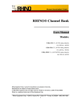
USER MANUAL
Sweetlight FR-252 MK2
DMX-controlled RGB 3-Segment LED Batten
User Manual: Sweetlight FR-252 MK2
■ Introduction
Dear customer,
congratulations on the purchase of this quality item and the trust having been put in us
with this decision. To take full advantage of all possibilities and for your own safety and
the safety of your environment, please read these operating instructions carefully
before you start using the unit.
■ Security advice before use
Warning: Read this section carefully before installing, powering,
operating, cleaning or servicing this product!
The following symbols are used to identify important safety information in this manual:
DANGER!
Safety hazard. Risk
of injury or death.
WARNING!
Hazardous voltage.
Risk of severe or
fatal electric shock.
WARNING!
Fire hazard.
WARNING!
Read manual before
installation and
operation.
General advice:
1. Read this manual completely before using the product.
2. Keep this manual in your records for future reference.
3. Follow all instruction printed in this manual, otherwise warranty
may be void.
4. Follow all printed security advice on the product itself. The lighting
flash with arrowhead within an equilateral triangle makes you
aware of non-insulated AC mains voltage inside the unit. The
exclamation mark within an equilateral triangle makes you aware of
important operating and maintenance instructions in the literature
attached to this product.
5. Take care of enough distance between this product and sources of
hum and noise like electric motors and transformers.
6. Carry this product with greatest care. Punches, big forces and
heavy vibration may damage this product mechanically.
7. The manufacturer takes no responsibility for injury or damage
caused by not following the safety precautions and instructions
printed in this manual.
Warning! Class 1M LED product.
1. Do not look into the beam from a distance of less than 40 cm (16
inches).
2
User Manual: Sweetlight FR-252 MK2
2.
3.
Do not stare into the beam for extended periods at a short
distance.
Do not view the beam directly with optical instruments such as
magnifiers.
Protection from electric shock:
1. Do not connect the AC power plug to the unit before assembly has
been completed.
2. Only connect this unit to a mains socket outlet with protective earth
connection, ground-fault (earth-fault) protection and overload
protection.
3. Where the mains plug or an appliance coupler is used as a disconnect device, the disconnect device shall remain readily
operable.
4. To pull the AC Cord out of the wall outlet or the unit’s AC socket,
never pull the cable itself, but only the AC plug.
5. Disconnect the unit from AC supply by pulling the AC plug out of
the wall outlet or the unit’s AC socket before any kind of cleaning
on the product. Use smooth and dry cloth only for cleaning. Check
all connection cables before reconnecting the unit.
6. Do not expose this unit to any dripping or splashing liquids, and do
not place objects filled with liquids, such as vases, on the unit. Do
not operate this unit near to open water or in high humidity.
7. Choose the position of the AC cord according to the lowest risk of
damage by foot steps or by squeezing it. Take especially care of
the AC cord outlet on the unit as well as the AC plug and wall outlet
at the other end of the cable.
8. Do not open the unit for service purpose, as there are no userserviceable parts inside. Warranty will be void in any case of
unauthorized service by the user or other not authorized persons.
Protection from fire:
1. Take care of not placing the unit near sources of heat (e.g.
powerful amplifiers, fog machines).
2. Allow at least about 6” (15cm) between this unit and other devices
or a wall to allow for proper cooling.
3. Be sure this fixture is kept at least 0.5m away from any flammable
materials (decoration etc.).
4. Do not stick filters, masks or other materials directly on the LEDs or
the LED cover screen.
5. Take always care of sufficient air convection in the unit’s
environment to avoid overheating, especially when mounting in a
closed environment. Make sure air convection slots are not
blocked. Do not operate this unit in environmental temperatures
exceeding 35 degrees Celsius.
6. Check the total maximum power of your AC wall outlet if you
3
User Manual: Sweetlight FR-252 MK2
connect several units to one wall outlet and avoid any overloading.
Protection from injury and damage:
1. Never use any accessories or modifications not authorized by the
manufacturer of this unit.
2. Choose a location for operation where the unit is protected from
vibration and where a fixed mounting position is provided. In case
of overhead-mounting, follow appropriate rigging rules and your
country’s regulations for rigging safety. See appendixes if any.
3. Before plugging the AC cord in the wall outlet, check whether the
AC mains voltage and frequency is the same as this product is
specified for. Whenever your AC plug should not match the wall
outlet, contact you dealer immediately.
4. If fluids have spilled into the unit or small parts have intruded the
unit, immediately switch off the unit and hand it over to the
authorized service for a security check.
5. Disconnect the unit from AC supply by pulling the AC plug out of
the wall outlet or the unit’s AC socket during a thunder-storm in
order to avoid any damage on the unit due to AC voltage peaks.
6. In cause of not correct function of this unit or damaged AC cord or
other damaged parts, pull immediately the AC plug out of the wall
outlet and hand the unit over to the authorized service for a
security check.
7. To meet all aspects of functionality and security during maintenance work to be preformed on this unit, all parts should be
replaced by genuine spare parts. Consequently, take care of your
dealer or maintenance company to be authorized by the
manufacturer.
■ Health advice
This unit produces and absorbs electromagnetic radiation. The strength of radiation and
the sensitivity for disturbing interference matches the CE and FCC requirements. A
corresponding sign is printed on the backside of the unit. Any change or modification
may affect the behavior of the unit concerning electromagnetic radiation, with the CE
requirements eventually not to be met any more. The manufacturer takes no
responsibility in this case.
■ Functional advice
This unit is immune to the presence of electromagnetic disturbances – both conducted
and radiated - up to a certain level. Under peak conditions, the unit is classified to show
a “class C” performance criteria and may encounter temporary degradation or loss of
function which may need manual help to recover. In such case, disconnect the AC
power from the unit and reconnect it again to recover.
4
User Manual: Sweetlight FR-252 MK2
■ Environmental advice
This unit is build to conform to the ROHS standards and the WEEE
directive 2002/96/EC of the European Parliament and of the Council of
the European Union. Under these regulations, the product shall not be
discarded into regular garbage at the end of its life, but shall be returned
to authorized recycling stations.
■ Unpacking
Please check that the box contains the following items:
Main parts:
1 pcs. Sweetlight FR-252 MK2 main unit
1 pcs. mains cable
1 pcs. operation manual
If any part is missing, please contact your dealer immediately for replacement.
■ Getting started: choosing a location
Risk of fire: The Sweetlight FR-252 MK2 has been designed to work in
dry indoor environments at environmental temperatures up to 35
degrees Celsius. For proper operation, the unit must be operated with
unobstructed air convection to its outside metal case.
Do not:
Operate the Sweetlight FR-252 MK2 in environments with more than 35
degrees environmental temperature or more than 75% relative humidity.
Operate the Sweetlight FR-252 MK2 in any closed environment smaller than
10cbm, unless forced air convection is provided.
■ Getting started: secure mounting
The Sweetlight FR-252 MK2 can be mounted in various ways:
Floor standing operation
•
•
•
Turn the brackets to the lower side of the unit.
Place the unit in a secure position where it can neither be touched by anyone or
could possibly become an objective for anyone to stumble.
Make sure to comply with cooling requirements of the used power supply if any.
5
User Manual: Sweetlight FR-252 MK2
Hanging/Rigging, ceiling-mounted operation
Risk of injury: Overhead mounting requires extensive experience,
including among others calculating working load limits, good knowledge
of the installation material being used, and periodic safety inspection of
all installation material and the unit. If you lack such qualifications, do
not attempt the installation yourself. Improper installation can result in
body injury. Be sure to complete all rigging and installation procedures
before applying power to the unit.
•
•
•
•
•
•
•
•
The unit should be installed out of reach of people and outside areas where
persons may walk by or be seated.
Make sure that the installation area can hold a minimum point load of 10 times the
device’s weight.
In fixed installations, fix the unit with self-locking screws/nuts to the mounting point.
When mounting the unit to truss be sure to secure an appropriately rated clamp to
the hanging yoke using a M10 screw fitted through the center hole of the hanging
yoke.
Where required, secure the installation with an appropriate safety cable. Always
use a certified safety cable that can hold 12 times the weight of the device when
installing the unit. This secondary safety attachment should be installed in a way
that no part of the installation can drop more than 20cm if the main attachment
fails.
Never stand directly below the device when mounting, removing, or servicing the
fixture. Make sure the area below the installation place is free from unwanted
persons during rigging, de-rigging and servicing.
The operator has to make sure that the safety-relating and machine-technical
installations are approved by an expert before using them for the first time. The
installations should be inspected every year by a skilled person to be sure that
safety is still granted.
Make sure to comply with cooling requirements of the used power supply if any.
■ Getting started: making AC supply connections
Risk of fire / Safety risk
The Sweetlight FR-252 MK2 has an AC outlet that is designed to carry
loads of no more than 8A. Do not connect any high-power devices such
as audio power amplifiers, fog machines etc. to this outlet. Make sure
that all connected devices in a chain fed by the first device do not
exceed a maximum of 8A current consumption. All units must be
properly and separately earthed.
6
User Manual: Sweetlight FR-252 MK2
■ Operation
User interface overview:
1
2
3
4
5
6
7
8
MODE selection button
UP-Button
DOWN-Button
Display showing the Mode, DMX-address, etc.
DMX input
DMX output
AC output
AC input
Upon the user’s choice, the unit can work stand-alone with fixed colors or may be
controlled by external DMX-controllers. Available modes:
“A” Mode (Auto / DMX Master)
Press the MODE button (1) until the first digit on the display show “A”, indicating
operation in “A” mode. In this mode, a chaser or strobe preset can be displayed by the
unit. Use the UP/DOWN buttons (2/3) to choose one of the 25 presets as shown in the
list below.
In “A” mode, The unit does not receive any values from the DMX input but generates its
own chases and creates related DMX values on the output with channels 001 to 012 so
that similar units can show the same chase pattern if they are connected by DMX and
set to ”Slave Individual” mode “SLI” (see DMX channel assignment under “notes”). The
level at all programs is 100%. The speed is set to 2Hz (120 BPM) with hard switching
between the steps.
7
User Manual: Sweetlight FR-252 MK2
If you leave mode “A” for any reason and come back later into mode “A”, the unit will
recall the last chosen color preset (even if the unit was switched off in between). The
factory default is A10. Hence switching on the unit for the first time directly gives a light
output and the user then may choose any other pattern out of the following:
A10 Chase 1 with Mood 0 ….. A17 Chase 1 with Mood 7
A20 Chase 2 with Mood 0 ….. A27 Chase 2 with Mood 7
A30 Chase 3 with Mood 0 ….. A37 Chase 3 with Mood 7
A40 all white strobe (16 Hz)
A41 all red strobe (16 Hz)
A42 all green strobe (16 Hz)
A43 all blue strobe (16 Hz)
“CI“ Mode (Colour Individual Preset Mode)
Press the MODE button (1) until the first two digits on the display show “CI”, indicating
operation in “CI” mode. In this mode, a combination of different colours for the three
sections of the LED panel can be chosen as a static preset. Use the UP/DOWN buttons
(2/3) to choose one of the 13 color presets as shown in the list below. Changing the
setting becomes effective directly. The output level us maximum.
In “CI” mode, the unit does not receive any values from the DMX input but generates its
own set of mixed colours for the three LED panel section. It creates related DMX values
on the output with channels 001 to 012 so that similar units can show the same colour if
they are connected by DMX and set to “Slave Individual” mode “SLI” (see DMX channel
assignment under “notes”).
If you leave mode “CI” for any reason and come back later into mode “CI”, the unit will
recall the last chosen color preset (even if the unit was switched off in between).
Display
CI0
CI1
CI2
CI3
CI4
CI5
CI6
CI7
CI8
CI9
Section 1
OFF
Red
Green
Blue
Red
Green
Blue
Green
Lavender
Pink
Section 2
OFF
Green
Red
Red
Blue
Blue
Green
Orange
Frog
Turquoise
Section 3
OFF
Red
Green
Blue
Red
Green
Blue
Green
Lavender
Pink
“C” Colour Mode
Press the MODE button (1) until the first digit on the display shows “C”, indicating
operation in “C” mode. In this mode, one single color for all three sections of the LED
8
User Manual: Sweetlight FR-252 MK2
panel can be chosen as a static preset. Use the UP/DOWN buttons (2/3) to choose
one of the 13 color presets as shown in the list below. Changing the setting becomes
effective directly. The output level us maximum.
In “C” mode, the unit does not receive any values from the DMX input but generates
related DMX values on the output according to the selected color, so that further units
can show the same behaviour if they are connected by DMX signal cables and set to
Slave Mode “SLA”.
If you leave mode “C” for any reason and come back later into mode “C”, the unit will
recall the last chosen color (even if the unit was switched off in between).
Available colour presets:
C0
C1
C2
C3
C4
C5
C6
all off
Red
Green
Blue
Yellow
Pink
Turquoise
C7
C8
C9
C10
C11
C12
C13
Lime
Orange
Marine
Frog
Lavender
Candy
White
“dI” Mode (DMX Individual Mode)
Press the MODE button (1) until the display shows “dI”, indicating operation in “dI”
(DMX Individual) mode. Shortly after that, the display shows the DMX starting address.
In this mode, the unit receives DMX values on a packet of twelve channels for
individual DMX control of the 3 segments, and mirrors the received data on the DMX
output. You can choose any DMX starting address by simply using the UP/DOWN
buttons (2/3). The chosen DMX-address comes effective approximately 3 seconds later
and will show up on the display (4) in alternation to the “dI”. This allows control of the
unit by any external DMX signal. Once such signal is received, a LED on the lower right
side of the “d” in the display indicates that a DMX signal is present. All settings are
stored even when the device is switched off. Factory default = channel 001.
Addressing has hence to be done as follows:
001 first Device (ch1-12)
013 second device (ch13-24)
025 third device (ch25-36)
*factory default*
and so on.
The twelve channels control the unit as follows:
CH1:
CH2:
Segment 1/Red intensity
Segment 1/Green Intensity
9
User Manual: Sweetlight FR-252 MK2
CH3:
CH4:
Segment 1/Blue intensity
Segment 1/ value 000-127 = Master dimmer (overall weighting to the values received on
CH1/2/3), Strobe off
value 128-227 =
Strobe (128= slow / 227= max. speed 23 Hz)
value 228-255 =
Master dimmer full on, Strobe off
CH5:
Ch6:
CH7:
CH8:
Segment 2/Red intensity
Segment 2/Green Intensity
Segment 2/Blue intensity
Segment 2/ value 000-127 = Master dimmer (overall weighting to the values received on
CH1/2/3), Strobe off
value 128-227 =
Strobe (128= slow / 227= max. speed 23 Hz)
value 228-255 =
Master dimmer full on, Strobe off
CH9:
Ch10:
CH11:
CH12:
Segment 3/Red intensity
Segment 3/Green Intensity
Segment 3/Blue intensity
Segment 3/ value 000-127 = Master dimmer (overall weighting to the values received on
CH1/2/3), Strobe off
value 128-227 =
Strobe (128= slow / 227= max. speed 23 Hz)
value 228-255 =
Master dimmer full on, Strobe off
“d” Mode (DMX Mode)
Press the MODE button (1) until the display shows “d”, indicating operation in “d”
(DMX) mode. Shortly after that, the display shows the DMX starting address. In this
mode, the unit receives DMX values on a packet of four channels for mutual DMX
control of all 3 segments, and mirrors the received data on the DMX output. You can
choose any DMX starting address by simply using the UP/DOWN buttons (2/3). The
chosen DMX-address comes effective approximately 3 seconds later and will show up
on the display (4) in alternation to the “d”. This allows control of the unit by any external
DMX signal. Once such signal is received, a LED on the lower right side of the “d” in
the display indicates that a DMX signal is present. All settings are stored even when the
device is switched off. Factory default = channel 001. Setting are stored even if the
device is switched off. The four channels control the unit as follows:
DMX channel
Value Range
Function
CH1
CH2
CH3
CH4
000-255
000-255
000-255
000-127
128-227
228-255
Out1 level
Out2 level
Out3 level
Master level
Tact (128=slow / 227=max. speed 23 Hz)
Master level full on, Tact off
Addressing has to be done as follows:
001 first device
(CH 1-4)
005 second device
(CH 5-8)
009 third device
(CH 9-12)
013 fourth device
(CH 13-16)
*factory default*
and so on.
10
User Manual: Sweetlight FR-252 MK2
“SLI” Mode (DMX Individual Slave)
Press the MODE button (1) until the display shows “SLI”, indicating operation in “SLI”
(SLAVE INDIVIDUAL) mode. In this mode the unit is set to DMX-channel 001 in order
to receive the DMX signal on 12 consecutive channels starting from 001 from a masterunit being in mode "CI" or “A”. Once such signal is received, a LED on the lower right
side of the “C” in the display indicates that a DMX signal is present.
This mode can also be used for remotely controlling the whole unit with individual
settings for the 3 segments if no specific DMX address is needed and channels 001012 can serve as a default.
“SLA” Mode (DMX Slave)
Press the MODE button (1) until the display shows “SLA”, indicating operation in “SLA”
(SLAVE) mode. In this mode the unit is set to DMX-channel 001 in order to receive the
DMX signal on 4 consecutive channels starting from 001 from a master-unit being in
mode "C". Once such signal is received, a LED on the lower right side of the “C” in the
display indicates that a DMX signal is present.
This mode can also be used for remotely controlling the whole unit with same settings
for all 3 segments if no specific DMX address is needed and channels 001-004 can
serve as a default.
Display on/off
The display of the unit will turn off after 25 seconds of not receiving any user
commands through the buttons 1/2/3. On the first hit of any button, the display will light
up again; this first hit will not change any settings, only when you press any button after
that, settings will be affected.
Key lock
Pressing the MODE button (1) for longer than 3 seconds locks all the buttons (1/2/3).
The display shows “LOC” in alteration to the mode (changing every 2 seconds).
Pressing the MODE button again for more than 3 seconds unlocks the button- and
potentiometer-functions. Please note: If the display is in OFF-mode it will take
approximately 25 seconds before the display switches off. It will be switched on again if
any key is touched and will switch off again after 25 seconds if the keys are not
unlocked by the procedure mentioned above.
Termination
To avoid interference the last unit of a DMX-chain should be terminated. Use a
standard 120 Ohms XLR termination plug for DMX lines on the last device in a DMX
bus chain.
11
User Manual: Sweetlight FR-252 MK2
Switch on condition
The unit always returns to the last mode before it was switched off. In DMX Slave “SLA”
/”SLI”or DMX Mode “d”/”dI” all DMX values are cleared if power is switched off.
DMX signal drop condition
The device will retain the status that it was in before the DMX signal got lost, but
potential tact settings will be automatically cleared.
■ Maintenance
This unit does not need regular maintenance. The internal circuit is protected by a
250V/2A slow-blow fuse 5x20mm fuse. If this fuse fails, this usually indicates an
internal fault requiring servicing by a qualified engineer. The fuse shall only be replaced
by a fuse of same specification, and the replacement has to be made by qualified
personnel obeying applicable safety rules.
■ Technical data Sweetlight FR-252 MK2:
LEDs…..……...……252 pcs. 10mm LEDs (63 red – 108 green – 81 blue) in 3 segments
Dispersion angle………………………………………………………….………...30 degrees
Mains Input……………………………………………………………. AC90-250V~ 50/60Hz
Power supply type………………………………………………………….……..switch mode
Power Consumption…………………….…………………………………………...max. 20W
Fuse………………………………………………….250V 2A T (slow blow, 5x20mm glass)
DMX connections…………………………………………………3 pin XLR (Male / Female)
Modulation Type…………………….…………….Advanced Bit Angle Modulation (ABAM)
Control protocol.......................................................................................DMX 512 (1990)
Dimensions (without brackets)………………….……….L1064.00 x H64.00 x D66.00 mm
Weight …………………………………………………………………………………….1.93kg
■ Standards
This product complies with the following standards:
EU safety................................................................EN60598-1:2008, EN60598-2-1:1989
EU EMC.......................................EN55015: 2006 + A1:2007, EN61547:1995 + A1:2000
EU Harmonics ...................................................................................EN61000-3-2:2006
EU Flicker ………………………………………………………………….EN61000-3-3:2008
US safety ………….…………..………………………………………………………UL60065
US EMC………………………..…………………………………………………..FCC Part 15
This product meets both the EMC Directive 2004/108/EC and the Low Voltage Directive
2006/95/EC.
12