1
AR-B5890 User Manual
AR-B5890 Board
Intel GM45 with Core 2 Duo CPU board
User Manual
Manual Rev.: 1.0
Book Number: AR-B5890-2009.11.27
1
AR-B5890 User Manual
Revision
Version
1.0
Date
Author
2009.11.27 Ken
Description
2
AR-B5890 User Manual
Copyright 2009
All Rights Reserved.
Manual’s first edition:
For the purpose of improving reliability, design and function, the information in this document is
subject to change without prior notice and does not represent a commitment on the part of the
manufacturer.
In no event will the manufacturer be liable for direct, indirect, special, incidental, or
consequential damages arising out of the use or inability to use the product or documentation, even
if advised of the possibility of such damages.
This document contains proprietary information protected by copyright. All rights are reserved.
No part of this Manual may be reproduced by any mechanical, electronic, or other means in any
form without prior written permission of the manufacturer.
Trademarks
AR-B5890 is a registered trademarks of Acrosser; IBM PC is a registered trademark of the
International Business Machines Corporation; Pentium is a registered trademark of Intel
Technologies Inc; Award is a registered trademark of Award Software International Inc; other
product names mentioned herein are used for identification purposes only and may be trademarks
and/or registered trademarks of their respective companies.
3
AR-B5890 User Manual
Table of Contents
1 INTRODUCTION.................................................................................... 5
1.1 SPECIFICATIONS .................................................................................................. 6
1.2 PACKAGE CONTENTS........................................................................................... 7
1.3 BLOCK DIAGRAM ................................................................................................ 8
2 H/W INFORMATION .............................................................................. 9
2.1 LOCATIONS (TOP SIDE) ........................................................................................ 9
2.2 LOCATIONS (BOTTOM SIDE)................................................................................ 11
2.3 CONNECTORS AND JUMPER SETTING .................................................................. 12
2.4 CONNECTORS AND JUMPER SETTING TABLE........................................................ 13
3 WATCHDOG, GPIO PROGRAMMING ................................................ 16
4 BIOS SETTING .................................................................................... 21
4.1 MAIN SETUP ..................................................................................................... 22
4.2 ADVANCED CHIPSET SETUP ............................................................................... 23
4.3 POWER SETUP .................................................................................................. 25
4.4 PNP/PCI SETUP ............................................................................................... 26
4.5 PERIPHERALS SETUP ........................................................................................ 28
4.6 PC HEALTH SETUP ........................................................................................... 29
4.7 BOOT SETUP .................................................................................................... 30
4.8 EXIT SETUP ...................................................................................................... 31
5 ELECTRICAL CHARACTERISTICS ................................................... 33
5.1 BASIC ELECTRICAL CHARACTERISTICS TABLE ..................................................... 33
4
AR-B5890 User Manual
1
INTRODUCTION
AR-B5890 incorporates the advanced Intel® GM45 & ICH9M Chipset. Intel® GM45 chipset
supports the Intel Core 2 Duo and Celeron M processors, while coming with a 667/800/1066MHz
Front Side Bus. It integrated Intel® GMA 4500MHD Graphic Core, brings great 3D graphic
performance for corporate and industrial application.
AR-B5890 provides outstanding video playback with high image quality, increased clarity, and
customization color controls. Enables enhanced visual quality of interlaced content on progressive
displays.
AR-B5890 is the best choice of industrial SBC. It provides high performance computing ability
and agile functions can help you build up outstanding embedded system.
5
AR-B5890 User Manual
1.1 Specifications
Intel® Core 2 Duo Mobile Processor for Mobile Intel GM45 Express Chipset Family.
Intel® GM45 & ICH9M chipset.
Intel® GMA4500MHD Graphic Core.
Dual Channel DDR3-1066MHz, max. 8GB.
Dual Channel 2x24-bit LVDS.
2 x SATA.
1 x CF II.
5 x RS232, 1 x RS232/422/485.
9 x USB2.0.
1 x PCI & 1 x PCI-E.
1 x GbE LAN.
8-bit GPIO.
DVI-D / TV-out interface.
6
AR-B5890 User Manual
1.2 Package Contents
Check if the following items are included in the package.
Quick Manual
AR-B5890
Software Utility CD X1
Note: When you install Microsoft Windows XP driver, please confirm the version of
Microsoft Windows XP operation system must be Service Pack 3 or later version, otherwise
the High Definition Audio Driver will install failed.
7
AR-B5890 User Manual
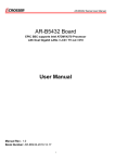
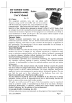
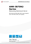
1.3 Block Diagram
8
AR-B5890 User Manual
2
H/W INFORMATION
This chapter describes the installation of AR-B5890. At first, it shows the function diagram and
the layout of AR-B5890. It then describes the unpacking information which you should read
carefully, as well as the connectors/jumper setting for the AR-B5890 configuration.
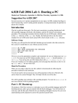
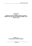
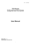
2.1 Locations (Top side)
9
AR-B5890 User Manual
DIMM
SO-DIMM Socket for DDR3.
BIOS
Serial Peripheral Interface Flash.
GMCH
Graphic Memory Control Hub Intel GM45.
CN5
2 USB and 1 RJ-45 for LAN.
ATX1
Power Connector for System Voltage.
ATX2
Power Connector 12V for CPU Voltage.
Processor
Socket for Pentium and Celeron mobile on 45nm
Celeron T1700,T1600,585 and 575 on 65nm.
BAT1
CR2032 Size Coin Battery.
AUDIO CHIP
Realtek ALC662.
SATA1 & SATA2
SATA Data Connector.
CN7
RS232 Serial Ports (COM1 & COM2).
CN8
RS232 Serial Ports (COM3 & COM4).
PCI1
PCI Socket (5V).
PCIE1
PCI Express x16 Socket.
ICH9 M
I/O Controller Hub 9 M.
LAN Chip
Intel 82574L Gigabit Ethernet.
DVI1
DVI-D Connector.
CN6
3 USB Connector.
10
AR-B5890 User Manual
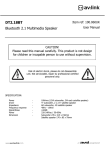
2.2 Locations (Bottom side)
11
AR-B5890 User Manual
2.3 Connectors and Jumper Setting
2.3.1 Locations (Top side)
LVDS
Connector for LVDS Signals
CN3 & CN4
Pin Header for 4 USB Ports
JP17
Switch for Select COM5
RS232/422/485
CN1
Connector for Back Light Inverter
COM5 & COM6
RS232 Serial Ports
JP13
Power Button & Reset & Buzzer &
Power LED & HD LED
JP1
Switch for Selecting 3V or 5V Panel
GPIO1
Pin Header for User-Defined GPIOs
JP11
JST Connector for Microphone
SYSFAN2
System Fan Connector
CPUFAN
CPU Fan Connector
JP14
JST Connector for Line In.
VGA1
Pin Header for D-Sub 15 Pin VGA
SYSFAN1
System Fan Connector
JP15
Keyboard Lock
TVOUT1
Pin Header for TV-OUT
JP3
RTC (Real Time Clock) Reset
KM1
JST Connector for Keyboard & Mouse
SYSFAN3
System Fan Connector
JP2 & JP4 & JP6
Front Side Bus Clock Strapping
JP18 & JP20
Select COM5 RS232/422/485
AUDIO1
Audio Output Connector (5.1 CH)
12
AR-B5890 User Manual
2.4 Connectors and Jumper Setting Table
2.4.1 LVDS (LVDS Signal)
2.4.2 CN1 (Back Light Inverter)
PIN
SIGNAL
PIN
1
LCDVCC
2
GND
3
B CLK-
4
B CLK+
B DATA2-
2.4.3 JP1 (Switch for Selecting
3V or 5V Panel)
SIGNAL
5
GND
6
7
B DATA2+
8
GND
9
B DATA1-
10
B DATA1+
11
B DATA3+
12
B DATA3-
13
B DATA0+
14
BDATA0-
15
GND
16
A CLK+
PIN
SIGNAL
17
A CLK-
18
GND
1
12V
19
A DATA2+
20
A DATA2-
2
12V
21
I2C CLK
22
A DATA1+
3
GND
23
A DATA1-
24
I2C DATA
STATUS
SIGNAL
25
A DATA0+
26
A DATA0-
4
Back Light On
1-2 Close
3.3V
27
A DATA3+
28
A DATA3-
5
GND
2-3 Close
5V
29
LCDVCC
30
LCDVCC
6
Back Light Control
2.4.4 SYSFAN2 (System Fan
Connector)
2.4.5 JP8 (Pin Header for
D-SUB 15 PIN VGA)
2.4.6 TVOUT1 (Pin Header for
TV-OUT)
PIN
PIN SIGNAL PIN
2
SIGNAL
SIGNAL
1
Y
2
DLINE3
GND
3
GND
4
DLINE2
PIN
SIGNAL
1
1
GND
3
G
4
GND
5
Pb
6
NC
2
12V
5
B
6
GND
7
GND
8
DLINE1
3
3.3V
7
VSYNC
8
SCL
9
Pr
10
GND
9
HSYNC
10
SDA
11
GND
12
NC
13
NC
14
NC
13
R
SIGNAL PIN
AR-B5890 User Manual
2.4.7 SYSFAN3 (System Fan
Connector)
2.4.8 JP18 & JP20 (Select
COM5 RS232/422/485)
2.4.9 CN3 & CN4 (Pin Header
for 4USB Ports)
JP18
STATUS
JP18
SETTING
1-3,2-4
PIN
SIGNAL
1
GND
2
12V
JP20 3-5, 4-6
3
3.3V
JP18 3-5, 4-6
RS-232
JP20
JP20
PIN SIGNAL
1
5V
2
5V
JP18 3-5, 4-6
3
-USB0
4
-USB1
5
+USB0
6
+USB1
7
GND
8
GND
9
GND
10
GND
RS-485
JP20
PIN
SIGNAL
1-3,2-4
RS-422
2.4.10 COM5 (RS-232/ RS-422/
RS-485 Serial Ports)
PIN
N/A
2.4.11 GPIO1 (Pin Header for
User-Defined GPIOs)
SIGNAL
PIN
SIGNAL
1
DCD
2
DSR(RX-)
3
RX(RX+)
4
RTS
1
5V
2
GND
5
TX
6
CTS(TX-)
3
GPIO30
4
7
DTR
8
RI(TX+)
5
GPIO31
9
GND
10
NC
7
9
PIN SIGNAL
2.4.12 CPUFAN (CPU Fan
Connector)
PIN SIGNAL
PIN
SIGNAL
GPIO34
1
Fan speed data
6
GPIO35
2
12V
GPIO32
8
GPIO36
3
GND
GPIO33
10
GPIO37
2.4.13 SYSFAN1 (System Fan
Connector)
2.4.14 JP3 & JP5 (RTC (Real
Time Clock)) Reset
PIN
SIGNAL
STATUS
1
Fan speed data
2
12V
3
GND
SETTING
JP3
JP5
1-2 close
Clear CMOS &
RTC
JP3
JP5
NC
Keep CMOS &
RTC
14
2.4.15 JP2 & JP4 & JP6 (Front
Side Bus Clock Strapping)
FSB
Auto
SETTING
JP2 1-2 close
JP4 1-2 close
JP6 1-2 close
AR-B5890 User Manual
2.4.16 AUDIO1 (Audio Output
Connector(5.1 CH))
PIN
SIGNAL
1
Front output right channel
2
Front output left channel
3
GND
4
GND
5
Low Frequency output
6
Center output
7
GND
8
GND
9
GND
10
GND
11
Surround out right channel
12
Surround out left channel
13
GND
14
NC
2.4.17 JP17 (Switch for Select
COM5 RS-232/422/485
STATUS
1-2 close
RS-232
3-4 close
RS-422
5-6 close
2.4.19 JP11 (JST Connector for
Microphone)
SETTING
RS-485
2.4.20 JP14 (JST Connector
for Line In
PIN
SIGNAL
PIN
SIGNAL
1
MIC IN
1
LINE IN RIGHT
2
GND
2
3
2.4.22 KM1 (JST Connector for
Keyboard & Mouse)
PIN SIGNAL PIN SIGNAL
1
MS data
4
5V
2
KB data
5
MS clock
3
GND
6
KB clock
15
2.4.18 JP13 (Power Button &
Reset & Buzzer & Power LED
&HD LED)
PIN
SIGNAL
1
Power LED +
2
Power LED-
3
HD LED+
4
HD LED-
5
Buzzer+
6
Buzzer-
7-8
9-1
0
Reset
Power Button
2.4.21 JP15 (Keyboard Lock)
PIN
SIGNAL
GND
Open
Keyboard Lock
LINE IN LEFT
Close
Keyboard Unlock
AR-B5890 User Manual
3
WATCHDOG, GPIO PROGRAMMING
GPIO Sample Code
//===========================================================================
// Turbo C++ Version 3.0 Copyright(c) 1990, 1992 by Borland International,Inc.
//===========================================================================
// Describe : GPIO30~GPIO37 Test utility for ITE8718F.
// Date
: 02/09/2009
// Author
: Willy
//===========================================================================
//===========================================================================
// Language include files
//===========================================================================
#include <conio.h>
#include <stdio.h>
//===========================================================================
// Normal procedure
//===========================================================================
void Show_Help();
void Show_Fail();
void Show_Pass();
//===========================================================================
// Main procedure
//===========================================================================
int main(int argc)
{
char *Model_Name="AR-B5890";
unsigned char
IO_PORT_BASE=0x2E; // DATA_PORT = IO_PORT_BASE + 1;
unsigned short int SIMPLE_IO_BASE;
unsigned char data;
int result=0;
if ( argc >1 )
{ Show_Help();
return 1;
}
clrscr();
textcolor(WHITE);
gotoxy(1, 1); cprintf("<>==========================================================================<>");
gotoxy(1, 2); cprintf("|| ITE8712F GPIO Test Utility v1.0 Acrosser Technology Co., Ltd.
||");
gotoxy(1, 3); cprintf("<>==========================================================================<>");
gotoxy(1, 4); cprintf("<>==========================================================================<>");
gotoxy(1, 5); cprintf("|| Model Name :
||");
gotoxy(1, 6); cprintf("|| SIO IO Base :
||");
gotoxy(1, 7); cprintf("|| Simple I/O Base :
||");
gotoxy(1, 8); cprintf("<>==========================================================================<>");
// Enter ITE8712F Config
outportb(IO_PORT_BASE,0x87);
outportb(IO_PORT_BASE,0x01);
outportb(IO_PORT_BASE,0x55);
outportb(IO_PORT_BASE,0x55);
// Select Logic Device number 7
outportb(IO_PORT_BASE,0x07);
outportb(IO_PORT_BASE+1,0x07);
// Set Multi-function Pins to GPIO30~GPIO37
outportb(IO_PORT_BASE,0x27);
outportb(IO_PORT_BASE+1,0xFF);
// GPIO30~GPIO37 Used Simple I/O Finction
outportb(IO_PORT_BASE,0xC2);
outportb(IO_PORT_BASE+1,0xFF);
16
AR-B5890 User Manual
// Get Simple I/O Base Address
outportb(IO_PORT_BASE,0x62);
// Simple I/O Base address MSB
SIMPLE_IO_BASE=inportb(IO_PORT_BASE);
SIMPLE_IO_BASE=SIMPLE_IO_BASE<<8;
outportb(IO_PORT_BASE,0x63);
// Simple I/O Base address LSB
SIMPLE_IO_BASE=SIMPLE_IO_BASE|inportb(IO_PORT_BASE);
// Show Got Parameter Informat
textcolor(LIGHTGRAY);
gotoxy(18,5);
cprintf("%s",Model_Name);
gotoxy(18,6);
cprintf("%X",IO_PORT_BASE);
gotoxy(22,7);
cprintf("%X",SIMPLE_IO_BASE);
// Set GPIO30~33 to Output, GPIO34~GPIO37 to Input
outportb(IO_PORT_BASE,0xCA);
outportb(IO_PORT_BASE+1,0x0F); // bit=1 , output
// Set GPIO30~33 to High
outportb(SIMPLE_IO_BASE+2,0x0F);
// Read GPIO34~37 Status, if not High error.
data=inportb(SIMPLE_IO_BASE+2)&0xF0;
if(data!=0xF0)
result=1;
// Set GPIO30~33 to Low
outportb(SIMPLE_IO_BASE+2,0x00);
// Read GPIO34~37 Status, if not Low error.
data=inportb(SIMPLE_IO_BASE+2)&0xF0;
if(data!=0x00)
result=1;
// Set GPIO30~33 to Input, GPIO34~GPIO37 to Output
outportb(IO_PORT_BASE,0xCA);
outportb(IO_PORT_BASE+1,0xF0); // bit=1 , output
// Set GPIO34~37 to High
outportb(SIMPLE_IO_BASE+2,0xF0);
// Read GPIO30~33 Status, if not High error.
data=inportb(SIMPLE_IO_BASE+2)&0x0F;
if(data!=0x0F)
result=1;
// Set GPIO34~37 to Low
outportb(SIMPLE_IO_BASE+2,0x00);
// Read GPIO30~33 Status, if not Low error.
data=inportb(SIMPLE_IO_BASE+2)&0x0F;
if(data!=0x00)
result=1;
// Exit ITE8712F Config
outportb(IO_PORT_BASE,0x02);
outportb(IO_PORT_BASE+1,0x02);
if(result)
Show_Fail();
else
Show_Pass();
return result;
}
void Show_Help()
{
clrscr();
printf("GPIO Test utility for ITE8712F\n\n");
printf("Vcc GND \n");
printf("GP30 迋迋迋迋? GP34\n");
printf("GP31 迋迋迋迋? GP35\n");
printf("GP32 迋迋迋迋? GP36\n");
printf("GP33 迋迋迋迋? GP37\n");
}
//===========================================================================
// Function : Show_Fail()
// Input
:-
17
AR-B5890 User Manual
// Change
:// Return
:// Description : Show Fail Message.
//===========================================================================
void Show_Fail()
{
}
//===========================================================================
// Function : Show_Pass()
// Input
:// Change
:// Return
:// Description : Show Pass Message.
//===========================================================================
void Show_Pass()
{
}
18
AR-B5890 User Manual
WATCHDOG TIMER
//===========================================================================
// Turbo C++ Version 3.0 Copyright(c) 1990, 1992 by Borland International,Inc.
//===========================================================================
// Describe : ITE8718F WatchDog timer test
// Date
: 12/16/2009
// Author
: Willy
//===========================================================================
#include <conio.h>
#include <stdlib.h>
#include <stdio.h>
#include <dos.h>
//===========================================================================
//
Main procedure
//===========================================================================
int main(int argc, char *argv[])
{
unsigned char IO_Port_Address=0x2E;
unsigned char Time;
unsigned int Temp;
long int Time1 = 0, C = 0;
if ( argc != 2 )
{
Show_Help();
return 1;
}
clrscr();
Time=atoi(argv[1]);
// Set Watchdog
outportb(IO_Port_Address,0x87);
// Enter configure
outportb(IO_Port_Address,0x01);
outportb(IO_Port_Address,0x55);
outportb(IO_Port_Address,0x55);
outportb(IO_Port_Address,0x07);
// Point to Logical Device Number Reg.
outportb(IO_Port_Address+1,0x07); // Select logical device 7, (Watchdog Function)
outportb(IO_Port_Address,0x23);
// Select Watchdog use CLKIN
outportb(IO_Port_Address+1,inportb(IO_Port_Address+1)|0x10);
outportb(IO_Port_Address,0x72);
// Select Watchdog use keyboard reset
outportb(IO_Port_Address+1,0x40);
outportb(IO_Port_Address,0x72);
// Select Watchdog count mode seconds or minutes
outportb(IO_Port_Address+1,inportb(IO_Port_Address+1)|0x80); // Set Second
if (Time != 0)
{
Time1 = Time;
C = ( Time1 * (0x64) ) / (0x6C);
// Time = Time * 1.08 (offset)
19
AR-B5890 User Manual
outportb(IO_Port_Address,0x73);
// Set Watchdog Timer Value
outportb(IO_Port_Address+1, C);
// 0x00 to disable, max 0xFF
while (Time > 0)
{
clrscr();
gotoxy(35,12);
Time = Time - 1;
printf("After %d (s) to reset" , Time);
delay(1000);
}
textcolor(LIGHTRED);
gotoxy(18,10);
delay(5000);
cprintf("If you can see this message, Reset system is Fail",Time);
}
return 0;
}
Note: The WatchDog Timer Fuction has ±5% torence.
20
AR-B5890 User Manual
4
BIOS SETTING
This chapter describes the BIOS menu displays and explains how to perform common tasks
needed to get the system up and running. It also gives detailed explanation of the elements found
in each of the BIOS menus. The following topics are covered :
Main Setup
Advanced Chipset Setup
Power Setup
PnP/PCI Setup
Peripherals Setup
PC Health Setup
Boot Setup
Exit Setup
21
AR-B5890 User Manual
4.1 Main Setup
Once you enter the Award BIOS™ CMOS Setup Utility, the Main Menu will appear on the
screen. Use the arrow keys to highlight the item and then use the <Pg Up> <Pg Dn> keys to select
the desired value in each item.
Note: The control keys are listed at the bottom of the menu. If you need any help with the item fields, you
can press the <F1> key, and the relevant information will be displayed.
Option
Choice
Description
Date Setup
N/A
Set the system date. Note that the ‘Day’
automatically changes when you set the
date.
Time Setup
N/A
Set the system time.
IDE Channel 0
Master/Slave
N/A
The onboard SATA Ports support user
connecting up to 2 SATA HDD.
The first SATA Port is the “IDE Channel 0
Master” and the second is “IDE Channel 1
Master”. BIOS will auto-detect the HDD type.
Halt On
All Errors,
No Errors,
All but keyboard.
Select the situation in which you want the
BIOS to stop the POST process and notify
you.
22
AR-B5890 User Manual
4.2 Advanced Chipset Setup
Option
Choice
Description
Quick Power On Self Test
Enabled
Disabled
This category speeds up the Power On
Self Test (POST) after you have powered
on the computer. If it is set to Enabled, the
BIOS will shorten or skip some check
items during POST.
Full Screen Logo Show
Enabled
Disabled
Select Enabled to show the full screen
logo if you have an add-in BIOS.
APIC Mode
Enabled
Disabled
Select Enable or Disable the APIC Mode.
PEG/Onchip VGA Control
Auto
PEG Port
On Chip
Forced or auto detecting Onboard VGA/
PCIE VGA Card.
INIT Display First
PCI Slot
Onboard
PCIEx
Select Init display first to VGA Card or
Onboard VGA.
23
AR-B5890 User Manual
On-Chip Frame Buffer
Size
32M
64M
128M
DVMT mode
Enabled
This item sets the mode for OS dynamic
video memory technology (DVMT).
Total GFX Memory
128M
256M
MAX.
The item sets DVMT size and handle by
VGA driver.
CRT
LFP
DVI
TV
For User selected the onboard display
combination.
CRT+CRT2
Boot Display
Pre-allocated main memory for onboard
VGA frame buffer.
(Option)
CRT+LFP
CRT+HDMI
(Option)
The CRT, LFP, DVI, and TV are onboard
features.
The CRT2 is optional and it’s from
AR-B2013 for VGA.
The HDMI is optional and it’s from
AR-B2013 for HDMI.
CRT+DVI
800 x 600
18bt
1024x768
18bt
For User selected the LCD Panel Type.
1280 x 1024 18bt
The 18 bt is for 18 bit LCD panel.
Panel Number
800 x 600
24bt
1024 x 768
24bt
The 24 bt is for 24 bit LCD panel.
1280 x 1024 24bt
24
AR-B5890 User Manual
4.3 Power Setup
Option
Choice
Description
ACPI Function
Enabled
25
ACPI System Support.
AR-B5890 User Manual
4.4 PnP/PCI Setup
Option
Reset Configuration
Data
Resources Controlled
By
Choice
Description
Enabled
Disabled
Normally, you leave this field
Disabled. Select Enabled to reset
the Extended System Configuration
Data (ESCD), when you exit Setup.
This may be necessary, if you have
installed a new add-on and the
system reconfiguration has caused
such a serious conflict that the
operating system can not boot.
Auto (ESCD)
Manual
The Award Plug and Play BIOS has
the capacity to automatically
configure all of the boot and Plug
and Play compatible devices.
However, this capability means
absolutely nothing unless you are
using a Plug and Play operating
26
AR-B5890 User Manual
system such as Windows 95 or
higher. If you set this field to
“Manual”, you may choose specific
resources by entering each of the
submenus.
IRQ Resources
When resources are controlled
manually, assign a type to each
system interrupt, depending on the
type of the device that uses the
interrupt.
N/A
27
AR-B5890 User Manual
4.5 Peripherals Setup
Option
Choice
Onboard Serial Port 1
Serial Port 1: 3F8 / IRQ11
Serial Port 2: 3E8 / IRQ10
Onboard Serial Port 2
Onboard Serial Port 3
Onboard Serial Port 4
Onboard Serial Port 5
Onboard Serial Port 6
Description
Serial Port 3: 2F8 / IRQ11
Serial Port 4: 2E8 / IRQ10
Serial Port 5: 228 / IRQ3
Serial Port 6: 238 / IRQ4
28
Select an address and the
corresponding interrupt for each
serial port.
AR-B5890 User Manual
4.6 PC Health Setup
This section shows the parameters for determining the PC Health Status. These parameters
include temperatures, fan speeds, and voltages.
Option
Choice
Description
The FAN will automatic spin up
or setting FAN active
temperature by user.
System Fan Control
Function
29
AR-B5890 User Manual
4.7 Boot Setup
Option
Choice
Description
First / Second / Third
Boot Device/Other Boot
Device
Hard Disk
CDROM
USB-FDD
Disabled
The BIOS attempts to load
the operating system from
the devices in the selected
sequence.
Hard Disk Boot Priority
N/A
These fields set the Boot
Priority for each Hard Disk.
CD-ROM Boot Priority
N/A
These fields set the Boot
Priority for each CR-ROM.
30
AR-B5890 User Manual
4.8 Exit Setup
Option
Save & Exit Setup
Choice
Press <Enter> on this item
to confirm:
Save to CMOS and EXIT
(Y/N)? Y
31
Description
Press “Y” to store the
selections made in the menus
in CMOS – a special section of
the memory that stays on after
you turn your system off. The
next time you boot your
computer, the BIOS configures
your system according to the
setup selections stored in
CMOS. After saving the values,
the system will restart.
AR-B5890 User Manual
Load Optimized
Defaults
When you press <Enter>
on this item, you will see a
confirmation dialog box
with a message like this:
Load Optimized Defaults
(Y/N)? N
Exit Without Saving
Press <Enter> on this item
to confirm:
Quit without saving
(Y/N)? Y
Press ‘Y’ to load the default
values that are factory-set for
optimal-performance system
operations.
This allows you to exit Setup
without storing any changes in
CMOS. The previous selections
remain in effect. This will exit
the Setup utility and restart your
computer.
When a password has been
enabled, you will be prompted
to enter your password every
time you try to enter Setup. This
prevents unauthorized persons
from changing any part of your
system configuration.
Type the password, up to eight
characters in length, and press
<Enter>. The password typed now
Set Password
Press <Enter> on this item
to confirm:
ENTER PASSWORD:
will clear any previous password
from the CMOS memory. You will
be asked to confirm the password.
Type the password again and
press <Enter>. You may also
press <Esc> to abort the selection
and not enter a password.
To disable a password, just press
<Enter> when you are prompted
to enter the password. A message
will confirm that the password will
be disabled. Once the password is
disabled, the system will boot and
you can enter Setup freely.
32
AR-B5890 User Manual
5
ELECTRICAL
CHARACTERISTICS
5.1 Basic Electrical Characteristics Table
Electrical Characteristics
Symbol
Value
Parameter / Condition
Unit
Min. Type. Max.
+12V
+12V power input
11.4 12
12.6
V
+5V
+5V power input
4.75 5.0
5.25
V
RS232
Maximum operating baud rate
Blight
LCD panel backlight operating voltage
T.P.C Total power consumption of ACE-B5890 without External device @ Pentium M 2.0 Ghz
33
-
-
11.4 12
-
33
115.2 Kbps
12.6
V
-
W