1
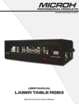
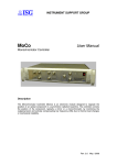
LASER SHOW SYSTEM
Jupiter
User's Manual
Tellus
DMX Address Chart
This chart lists the DMX dipswitch setting for DMX address 1 through 511. Follow the instructions below to configure fixture dipswitches with you desired DMX address.
DMX Address Quick Reference Chart
DipSwitch Position
DipSwitch Position
DMX Address
Page 9
General instructions
Jupiter
Notes:
1. DMX console can not be used in Master-Slave operation (Sound Active or AUTO mode ).
2. There should be only one master unit in Master-Slave operation.
Unpacking:
Thank you for purchasing this product. Please read user guide for safety and operations inf-
Jupiter
Troubleshooting
1. In Stand-Alone operation, if the power supply indicator is light up and sound active indic-
ormation before using the product. Keep this manual for future reference. This product can
create perfect laser programs and effects since it has passed a series of strictly tests before
delivery. Please check the attachments listed on the page after opening the carton. In the
ator isn't light up, but the laser is shut off doesn't work, Please check if unit has been set up
event of carton damage or attachment missing in transit, please contact your dealer or our
in slave mode, then set up in master mode.
after sales service department.
2. In Master-Slave operation, slave unit don't function, please check as below.
A. Make sure to there's only one master in the chain, and the others are set in slave mode.
Attachments:
B. Make sure to control the unit without DMX console controlling.
1. Laser Light:
1PCS
C. Make sure to take a good quality power cable and connection.
2. Power Cable:
1PCS
3. In DMX mode operation, the laser is OFF and the DMX signal indicator is unlighted, pl-
3. User Guide:
1PCS
ease check as below.
Make sure to set up the DMX mode, make sure to have a good connection.
4. In DMX operation, the unit can’t be controlled by the DMX console, but the DMX signal
Notice:
indicator is flashing, please make sure the DMX console and unit have the same channel.
1. Do not exposure the human eye direct to laser beam.
5. If the unit is fail, please turn off the unit, then turn on again after 5 minutes.
2. Do not turn on and off the unit frequently.
3. Before using this unit make sure the power supply is ground.
After trying the above solution you still have a problem, please contact your dealer or our
4. This unit is intended for indoor use only and should be prevented form water, moisture
company for service.
and shake. The working temperature of this unit is 18~30℃, do not use this continuously
over 4 hours, otherwise it shortens the lifetime of the unit.
5. Use cleaning tissue to remove the dust absorbed on the external lenses periodically to
optimize light output.
6. Do not remove or break the warranty label, otherwise it void the warranty.
7. Always replace with the exact same type fuse, replacement with anything other than the
specified fuse can cause fire or electric shock and damage your unit, and will void your manufactures warranty.
DANGER
LASER RADIATION AVOID EXPOSURE
TO BEAM CLASS 3B LASER PRODUCT
Page 8
Page 1
!
Jupiter
Technical Specification
5. The units will react to the low frequencies of music via the internal microphone. Adjust
the audio sensitivity knob on the back of the master unit to make the unit more or less se-
1. Voltage: □AC220V/ □110V, 50HZ/60HZ, Fuse 2A/250V
nsitive in sound active.The panel has LED indicating for sound active.
2. Rated Power: 80W
3. Scanner: High-speed optical scanner, big angle scanning
4. Laser:
Green laser: 532nm wavelength
POWER
POWER
1000mW
5. Working Modes: Sound Active, AUTO-Beam, AUTO-Animation, DMX512 (12 CH),
…………
1:MASTER:SOUND/AUTO
2:SLAVE
Master/Slave, PC Control
6. Graphics & Effects: 128 beam show and animated graphics show patterns
Universal DMX Operation (DMX mode)
7. Interface: 3 pins XLR jack for DMX or Maser-Slave linking
This mode allows you to use universal DMX-512 console to operate.
DB25/M ILDA computer interface for PC control
1. Install the units in a suitable position (laying or appending).
8. Size: 600*470*290mm
2. Use standard XLR microphone cable chain your units together via the XLR connector
9. Weight: 18
on the rear of the units. For longer cable runs we suggest a terminator at the last fixture.
3. Assign a DMX address to each the unit using dipswitches, see the "DMX Address Quick
Reference Char".
4. Turn on the all units' power, the units begins reset, then the unit begins working.
5. Use DMX console to control your units.
Jupiter
Features
1. RGB full-color animation laser with high-speed optical scanner to create animated graphics,
frequently flashing, rotating, moving, rotation, split, zoom, drawing, speed and color etc.
POWER
POWER
128 beam show and graphics show patterns, and with the function of unique blanking,
DMX Signal
…………
1:DMX MODE
2:DMX MODE
2. Includes six working modes as DMX512, Sound Active, AUTO-Animation, AUTOBeam, Master/Slave and PC control(with DB25 ILDA computer interface) for different
PC Control Operation
applications.
This mode allows you to use PC software(for example: Pangolin, Phenix, Mamba) to operate.
3. The unit has fourteen channels to control in DMX mode. The unit has BLACK OUT
function. The uint will shut off if no DMX512 signal.
4. Compatible ILDA laser show software with ILDA interface. Use electronic switches to
If no IDLA signal to DB25 jack in ILDA mode, the laser and scaner will is closed for protection. The scan speed of software coltrol must be less than 15000 PPS, otherwise, the patterns
possible have distortion, or the scaner is protected possibly by built-in circuitry.
conversion full ILDA signal. The uint will shut off if no ILDA signal.
5. Design according to security and good performance, safer to human and environment.
Master/Slave mode, DMX512 mode and PC Control mode, will shut off laser automatically without trigger signal.
ILDA Signal
Page 2
Page 7
POWER
One loop address=1, two loop address=17, three loop address=33, four loop address=49
Loop
Address
1
1
Binary
100000000
Jupiter
Front/Rear Panel
Dipswitches
1
#1 (#1 switch is ON, the others are OFF)
3
17
100010000
#1+#5 (#1 and #5 switches are ON)
3
33
100001000
#1+#6 (#1 and #6 switches are ON)
4
49
100011000
#1+#5+#6 (#1,5,6 switches are ON)
3
4
2
The dipswitches setting for DMX address see the " DMX Address Quick Reference Chart ".
Jupiter
Operation
Stand-Alone Operation (Sound Active, AUTO mode)
Front Panel Figure
1. Laser aperture
2. Sound active microphone
3. Sound active indicator:Blue
4. Power indicator:Red
The mode allows a single unit to react to the beat of the music in the master mode.
9
1. Install the units in a suitable position (laying or appending).
6
3
5
4
3
2
2. Set dipswitch to select Sound Active or AUTO mode.
3. Turn on the unit power, the unit begins reset, then the unit begins working.
4. The unit will react to the low frequencies of music via the internal microphone. Adjust
the audio sensitivity knob on the back of the unit to make the unit more or less sensitive in
sound active.The panel has LED indicating for sound active.
7
8
1
Rear Panel Figure
POWER
1: Master: Sound/AUTO
1. Power jack
2. Power switch
5. Audio sensitivity knob
3. Cooling fan
6. Function reference chart
4. Pattern size knob
7. DMX or linking jack
8. ILDA interface with DB25 jack
Master-Slave Operation
9. Function of built-in program setting dipswitches
This mode will allow you to link up to many units together without controller.
1. Install the units in a suitable position (laying or appending).
Jupiter
Function & Setting
2. Choose a unit to function as Master mode, set dipswitch to select Sound Active or AUTO
mode. The others must be set to Slave mode, set dipswitch to select Slave mode.
Sound Active
3. Use standard XLR microphone cable chain your units together via the XLR connector
The change of the laser pattern is controlled by sound, that is, the rhythm of the sound
on the rear of the units. For longer cable runs we suggest a terminator at the last fixture.
control the effect of the changing laser pattern.
4. Turn on the all units' power, the units begins reset, then the unit begins working. The
AUTO
slave units will react the same as the master unit.
Auto cycles the built-in programs without being controlled externally. It has no laser OFF.
Page 6
Page 3
DMX Control
The system only accepts the DMX512 signal of international standard to control the system.
DMX Control Parameter Chart
Channel
Function
Value
CH1
Mode
Channel
Function
CH12
Drawing
Value
CH3
Description
Function setting
If it is set to ILDA mode (use PC software to control laser light), just need to connect ILDA
100~149 Auto-Animation mode
signal to DB25 jack. If set to Built-in program, then ILDA signal cannot be connected,seting
150~199 Manual mode to Auto run
dipswitches directly is ok. ILDA mode (PC control) and Built-in program mode can be iden-
200~255 Manual mode to Sound Active run
tified and transisted automatically.
0=OFF
0~255
CH6
CH7
Moving-X
Rolling-X
Rolling-Y
DIPSWITCH CHART
CH9
Rotation
Zoom(+/-)
FUNCTION
fixed color~random single color~random
0
0
0
X
X
X
X
X
X
0 SOUND ACTIVE
three-color~moving three-color~fixed color
1
0
0
X
X
X
X
X
X
0 AUTO-BEAM
256 or 128 pattrens
1
1
0
X
X
X
X
X
X
0 AUTO-ANIMATION
Manual to up to down moving
0
0
1
X
X
X
X
X
X
0 SLAVE MODE
SET DMX ADDRESS
1 DMX MODE
Built-In Program Function Chart
Manual to left to right moving
128~191 Auto to right moving
DMX address calculation
192~255 Auto to left moving
For DMX mode, DMX address from #1 to 9# dipswitches must be set, the address is set
0~127
Manual rolling
from 1 to 511. Each dipswitch represents a binary value.
128~255 Auto rolling
Dipswitch
Value
Dipswitch
#1
1
#6
32
#2
2
#7
64
#3
4
#8
128
128~191 Auto clockwise rotation
#4
8
#9
256
192~255 Auto counter clockwise rotation
#5
16
#10
0~127
Manual rolling
128~255 Auto rolling
0~127
CH8
X=OFF or ON
#1 #2 #3 #4 #5 #6 #7 #8 #9 #10
128~191 Auto to down moving
0~127
1=ON
L818RGY: closed~red~green~yellow~
192~255 Auto to up moving
CH5
Auto drawing mode 2
Auto-Beam mode
Pattern Select 0~255
Moving-Y
128~255
50~99
0~127
CH4
Auto drawing mode 1
Sound Active mode
L816G: closed~no blanking~moving
Dimmer
0~127
0~49
blanking~flash blanking~blanking
CH2
Description
Manual rotation
Value
DMX, Set to "1"
0~85
Auto zoom(+)
One unit has 12 channels for DMX control, so each unit must be assigns 12 channels at least.
86~170
Auto zoom(-)
We may assign 16 channels for one unit, then DMX address = 16*N + 1, N=0, 1, 2, 3 ……
171~255 Manual zoom(+/-)
CH10
Pattern Size
0~255
0 is Moderate, 1 is small, 255 is big
CH11
Display Dot
0~255
0 is display dot, 255 is best brightness
Page 4
Example
Page 5
inst-
erate.
otec-
terns
DA
ting
den-
least.