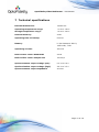
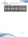
1
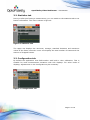
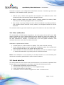
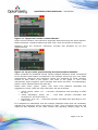
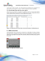
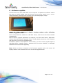
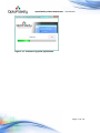
OptoFidelity Video Multimeter User Manual Version 2014Q2.0 OptoFidelity Oy • [email protected] • www.optofidelity.com OptoFidelity Video Multimeter – User Manual Contents 1 General information on OptoFidelity Video Multimeter ..................................... 3 2 Start window.............................................................................................. 3 3 Framerate measurement task ...................................................................... 4 4 5 3.1 Overview tab ....................................................................................... 4 3.2 Statistics tab ....................................................................................... 6 3.3 Configuration tab ................................................................................. 6 3.4 Color calibration................................................................................... 7 3.5 Saved data files ................................................................................... 7 Lip sync measurement option ....................................................................... 8 4.1 Lip sync option license activation ........................................................... 8 4.2 Audio input cable connection ................................................................. 8 4.3 Lip sync feature in Video Multimeter UI ................................................... 9 4.4 Saved data files with Lip sync option .....................................................11 USB connection .........................................................................................11 5.1 USB connection with Remote control API................................................12 6 Software update ........................................................................................13 7 Technical specifications ..............................................................................15 8 Change history ..........................................................................................16 Page 2 of 16 OptoFidelity Video Multimeter – User Manual 1 General information on OptoFidelity Video Multimeter OptoFidelity Video Multimeter is a compact desktop solution for measuring the true and objective video playback performance of mobile, tablet or any multimedia device directly from the display. It is controlled with a touch display. This resistive touch display works best with e.g. a finger nail or a stylus. 2 Start window When power is switched on, the device starts and Start Window opens up. All installed applications are listed in this window. List can be browsed by dragging or with the arrow buttons on the right. Figure 1: Start window after turning on the device. Applications are classified according to their purpose: Measurement tasks: Measurement applications, which are used to determine some feature of the device under test (DUT). Utilities: General utility programs for using and configuring Video Multimeter. Page 3 of 16 OptoFidelity Video Multimeter – User Manual 3 Framerate measurement task The framerate measurement task determines the playback smoothness of the DUT with a test video. A blinking marker is measured from the display of device, and this marker helps to determine frame intervals and missing frames. The basic measurement setup is shown in figure 2. Figure 2: Example of using Video Multimeter for frame rate measurement. 3.1 Overview tab When the frame rate measurement application is started, it opens to the overview tab shown in figure 3. On this tab, you can start and stop measurements, have an overview of the results and save them. The overview tab shows the average FPS over the whole measurement and the total number of frames. Figure 3: View of the application before measurement. Page 4 of 16 OptoFidelity Video Multimeter – User Manual To begin a new measurement, press the start button. The measurement will start immediately and continue until you press the stop button. While the measurement is ongoing, the graph will scroll to show the results, as shown in figure 4. Figure 4: Frame rate measurement in progress. The vertical axis of the graph indicates the time that each frame is on the screen. Readings on vertical axis are in milliseconds, so for example frame interval of 40 milliseconds equals to frame rate 1/0.040 = 25 FPS. Dropped frames are shown as red vertical bars if they occur. Note: To get repeatable results, start and stop the measurement in the white period at the start and end of the video. Such videos can be generated in OptoFidelity TVG by using setting calibration=both. After stopping the measurement, the results can be studied on the Stats tab, or saved using the Save button. After saving the results a message window shows the name of the saved file, like in figure 5. Figure 5: Message window after saving the measurement results. Page 5 of 16 OptoFidelity Video Multimeter – User Manual 3.2 Statistics tab During or after performing a measurement, you can switch to the statistics tab to see further information. The view is shown in figure 6. Figure 6: Statistics tab. The upper row displays the minimum, average, standard deviation and maximum values of the frame intervals. Lower row displays the total number of frames and the amount of dropped frames. 3.3 Configuration tab By default the application uses RGB marker with built-in color calibration. This is suitable for most measurement situations with LCD displays. For other kinds of displays, adjustments on the Config tab may be necessary. Figure 7: Configuration tab. Page 6 of 16 OptoFidelity Video Multimeter – User Manual As shown in figure 7, the configuration tab allows selection of marker type and color calibration. The available marker types are: 1. RGB (6-color): Marker with specific color sequence of 6 different colors. This measures frame intervals and detects dropped frames. 2. Black & White: Black and white marker. Simple method for testing frame intervals, but detecting dropped frames is not possible. 3. Any change: Any large change of color will be considered as a change of frame. Can measure frame intervals of any marker, but dropped frames will not be detected. The selected marker type must match the type of the marker in the test video used. 3.4 Color calibration The functionality of RGB marker depends on the color space of the DUT, since RGB marker is based on colors. Default settings can be applied for most LCD displays, but OLED displays and other display technologies may require calibration. You can easily see that calibration is needed, if red bars turn up on the graph constantly. This indicates that some colors have not been detected. Calibration is performed as follows: 1. Position fiber on a color marker on display. The video must be running. 2. Press Calibrate button on the Config tab. Calibration takes few seconds and fiber must be kept still on the marker during this time. 3. New calibration is valid immediately. If required, you can do calibration again or deactivate calibration by pressing the No calibration button. Note: Color calibration is only necessary for the RGB marker. It is not necessary and cannot be successfully performed for other kinds of markers. 3.5 Saved data files The saved data files from frame rate measurement are in semicolon separated CSV format. Each row corresponds to one frame, and has the following columns: 1. 2. 3. 4. Microsecond timestamp of the frame start. Microsecond length of the frame (-1 for dropped frames). Color of the marker in the frame. Cumulative count of frames dropped since start of measurement. Page 7 of 16 OptoFidelity Video Multimeter – User Manual Figure 8: Data file saved from frame rate measurement. The CSV format is supported by e.g. Microsoft Excel and many other data analysis tools. 4 Lip sync measurement option When activated, Framerate measurement task shall contain additional tab for Lip sync measurement. Lip sync measurement option measures the audio leading / lag values in milliseconds. Feature requires audio input, which is implemented by connecting 3.5mm audio jack to Video Multimeter’s Sensor interface. 4.1 Lip sync option license activation Lip sync option is activated by copying valid license file into Video Multimeter’s SDcard. License file name is “lipsync.ini”, and it should be copied into folder /frm/license/. The file contents is as follows: ; OptoFidelity Video Multimeter license file ; Device serial number: 5 ; Feature name: lipsync [License] salt = 1706318843 key = 2287536893 expire = 0 Device serial number must match the physical Video Multimeter device. License files are generated by OptoFidelity only. License files should not be edited manually. 4.2 Audio input cable connection Feature requires an audio input. 3.5mm audio jack cable must be connected to Sensor 1 interface. NOTE: Lip sync feature is activated only if the audio cable was physically connected to Video Multimeter before powering it up. Page 8 of 16 OptoFidelity Video Multimeter – User Manual Figure 9: Lip sync audio cable connected to Sensor 1 input. 4.3 Lip sync feature in Video Multimeter UI After the preconditions mentioned in the previous chapters are fulfilled (valid license file + audio cable connected), the Framerate task shows additional tab in the Video Multimeter UI. Figure 10: Framerate application Overview tab with lip sync feature activated. Additionally, Overview-tab contains indicator for momentarily lip sync value. Small blue marker in the graph shows the position where audio markers were detected. Lipsync-tab contains tools for adjusting the audio level, and indicators for visualizing the lip sync measurement statistics. Page 9 of 16 OptoFidelity Video Multimeter – User Manual Figure 11: Lipsync tab's Audio volume indicator. Audio volume indicator value should be especially observed during the audio markers. Marker detected –indicator flashes with blue color, when the marker is detected. Statistics show the minimum, maximum, average and deviation for lip sync measurements. Figure 12: Lip sync tab's graph showing the measurement statistics. Graph visualizes the statistical results. Square-shaped indicator’s width corresponds to the deviation and location corresponds to the average value of lip sync over whole measurement. Minimum and maximum values are visualized by small markers, located at both sides of the square. The scale of the graph is -200...+200 milliseconds, where negative value indicates that audio was early. Correspondingly, positive value indicates that audio was late. Graph scale colors (green, yellow, red) come from different standards and suggestions. Limits, which are only instructive, are set as follows: Green (Good): within -15 … +45 msec (Acceptance limit according to ATSC IS-191) Yellow (Moderate): within -45 … +125 msec (Human noticeable limit according to ITU-R BT.1359-1) Red (Poor): over -45 … +125 msec (Human noticeable limit according to ITUR BT.1359-1) It is important to understand, that for example moderate result does not necessarily indicate that measured video is perceived as “bad”. This is because the final user experince also depends on the video content and watching context (large TV set Page 10 of 16 OptoFidelity Video Multimeter – User Manual versus small mobile terminal). The abovementioned standards and suggestions are good reading, when product / service –specific acceptance limits are specified. 4.4 Saved data files with Lip sync option When the Lip sync feature is activated, an additional column of results data appears in the results data file. The column is named “Lip sync (ms)”. Measured Lip sync value is printed at each detected “k” frame (black color marker). Figure 13: Data file saved from frame rate measurement, including lip sync. 5 USB connection Video Multimeter can be connected to computer by a USB cable for battery charging and data transfer. Charging will begin as soon as the USB cable is connected and is indicated by a red LED next to the USB connector. When the battery is full, the LED will turn off. Note that if the device is on, the LED will not turn off because power is being used. Figure 14: USB mode selection screen. Page 11 of 16 OptoFidelity Video Multimeter – User Manual When the USB cable is connected and the device is on, a selection window such as in figure 9 opens up on the display. The window has options Data transfer and Charge only. If Data transfer is selected, the device will appear as an USB memory on the computer. Other functions of the device will not be available while the data transfer is active. Selecting Charge only will simply close the dialog so that the device can be used normally while it is being charged. 5.1 USB connection with Remote control API If remote control –feature is activated on the device, the selection screen has an additional selection. Figure 15: USB mode selection screen with Control API feature activated. By selecting Control API, the device is possible to be remotely controlled via USB. Please refer to the Video Multimeter Control Protocol –document for further information. Page 12 of 16 OptoFidelity Video Multimeter – User Manual 6 Software update Connect the device with USB cable to the computer to update the software. Switch the power on while holding down the button next to power switch by e.g. a pen. Video Multimeter’s display shows random noise (salt and pepper) image. Figure 16: Video Multimeter's display showing random noise, indicating firmware upgrade mode. Device should become visible as a USB DFU device, and drivers should be installed automatically. Start Firmware upgrade application by computer, and click Start button. Application informs when the software upgrade is done. Finally detach the device from computer and switch it off to exit the upgrade mode. If software update is interrupted for some reason, you can run the upgrade again as described above. Upgrade mode is separate from the main software, so damaged software does not prevent upgrading. Note: When the device is started in the firmware upgrade mode, the screen will display random noise. Reboot the device to exit the upgrade mode. Page 13 of 16 OptoFidelity Video Multimeter – User Manual Figure 17: Firmware upgrade application. Page 14 of 16 OptoFidelity Video Multimeter – User Manual 7 Technical specifications External dimensions: 12x8x3 cm Operating temperature range: -10 C to +40 C Storage temperature range: -20 C to +60 C Internal memory: 4 GB Operating time on battery: 6 hours Battery: Li-Ion Panasonic PA-L2, 1950 mAh, 7 Wh Operating current: 300 mA Built-in fiber sensor bandwidth 4 kHz Built-in fiber sensor sample rate 100 kS/s Synchronization output voltage (low) 0.0 V to 0.4 V Synchronization output voltage (high) 2.9 V to 3.3 V Synchronization output impedance 50 ohm Page 15 of 16 OptoFidelity Video Multimeter – User Manual 8 Change history Ver. 1.0 1.1 1.2 Status Draft Release Release Date 5.3.2013 7.5.2013 27.5.2013 Author KRY JPA JPA 1.3 Release 27.6.2014 KJO Remarks First release Release 2013Q1.0 FPS UI + file format Lip sync option, Remote control option Page 16 of 16