1
Hart Scientific
2200
Temperature Controller
User’s Guide
Rev. 710801
Limited Warranty & Limitation of Liability
Each product from Fluke Corporation, Hart Scientific Division ("Hart") is warranted to be free from defects in material and workmanship under normal use and service. The warranty period is 2 years for the
Temperature Controller. The warranty period begins on the date of the shipment. Parts, product repairs,
and services are warranted for 90 days. The warranty extends only to the original buyer or end-user customer of a Hart authorized reseller, and does not apply to fuses, disposable batteries or to any other product, which in Hart's opinion, has been misused, altered, neglected, or damaged by accident or abnormal
conditions of operation or handling. Hart warrants that software will operate substantially in accordance
with its functional specifications for 90 days and that it has been properly recorded on non-defective media. Hart does not warrant that software will be error free or operate without interruption. Hart does not
warrant calibrations on the Temperature Controller.
Hart authorized resellers shall extend this warranty on new and unused products to end-user customers
only but have no authority to extend a greater or different warranty on behalf of Hart. Warranty support is
available if product is purchased through a Hart authorized sales outlet or Buyer has paid the applicable
international price. Hart reserves the right to invoice Buyer for importation costs of repairs/replacement
parts when product purchased in one country is submitted for repair in another country.
Hart's warranty obligation is limited, at Hart's option, to refund of the purchase price, free of charge repair, or replacement of a defective product which is returned to a Hart authorized service center within
the warranty period.
To obtain warranty service, contact your nearest Hart authorized service center or send the product, with
a description of the difficulty, postage, and insurance prepaid (FOB Destination), to the nearest Hart authorized service center. Hart assumes no risk for damage in transit. Following warranty repair, the product will be returned to Buyer, transportation prepaid (FOB Destination). If Hart determines that the
failure was caused by misuse, alteration, accident or abnormal condition or operation or handling, Hart
will provide an estimate or repair costs and obtain authorization before commencing the work. Following
repair, the product will be returned to the Buyer transportation prepaid and the Buyer will be billed for
the repair and return transportation charges (FOB Shipping Point).
THIS WARRANTY IS BUYER'S SOLE AND EXCLUSIVE REMEDY AND IS IN LIEU OF ALL
OTHER WARRANTIES, EXPRESS OR IMPLIED, INCLUDING BUT NOT LIMITED TO ANY IMPLIED WARRANTY OF MERCHANTABILITY OR FITNESS FOR A PARTICULAR PURPOSE.
HART SHALL NOT BE LIABLE FOR ANY SPECIAL, INDIRECT, INCIDENTAL. OR CONSEQUENTIAL DAMAGES OR LOSSES, INCLUDING LOSS OF DATA, WHETHER ARISING FROM
BREACH OF WARRANTY OR BASED ON CONTRACT, TORT, RELIANCE OR ANY OTHER
THEORY.
Since some countries or states do not allow limitation of the term of an implied warranty, or exclusion or
limitation of incidental or consequential damages, the limitations and exclusions of this warranty may not
apply to every buyer. If any provision of this Warranty is held invalid or unenforceable by a court of competent jurisdiction, such holding will not affect the validity or enforceability of any other provision.
Fluke Corporation, Hart Scientific Division
799 E. Utah Valley Drive • American Fork, UT 84003-9775 • USA
Phone: +1.801.763.1600 • Telefax: +1.801.763.1010
E-mail: [email protected]
www.hartscientific.com
Subject to change without notice. • Copyright © 2005 • Printed in USA
Rev. 710801
Table of Contents
1 Before You Start . . . . . . . . . . . . . . . . . . . . . . . . . . 1
1.1
1.2
1.3
Introduction . . . . . . . . . . . . . . . . . . . . . . . . . . . . . . 1
Symbols Used . . . . . . . . . . . . . . . . . . . . . . . . . . . . 1
Safety Information . . . . . . . . . . . . . . . . . . . . . . . . . . 2
1.3.1
1.3.2
1.4
WARNINGS . . . . . . . . . . . . . . . . . . . . . . . . . . . . . . . . . . . 2
CAUTIONS . . . . . . . . . . . . . . . . . . . . . . . . . . . . . . . . . . . 4
Authorized Service Centers. . . . . . . . . . . . . . . . . . . . . . 5
2 Specifications and Environmental Conditions . . . . . . . . . . 9
2.1
2.2
Specifications . . . . . . . . . . . . . . . . . . . . . . . . . . . . . 9
Environmental Conditions . . . . . . . . . . . . . . . . . . . . . . 9
3 Quick Start . . . . . . . . . . . . . . . . . . . . . . . . . . . . 11
3.1
3.2
Unpacking . . . . . . . . . . . . . . . . . . . . . . . . . . . . . . 11
Set Up . . . . . . . . . . . . . . . . . . . . . . . . . . . . . . . . 11
3.3
Setting the Temperature . . . . . . . . . . . . . . . . . . . . . . . 11
4 Installation . . . . . . . . . . . . . . . . . . . . . . . . . . . . 13
4.1
4.2
Setup. . . . . . . . . . . . . . . . . . . . . . . . . . . . . . . . . 13
Heater . . . . . . . . . . . . . . . . . . . . . . . . . . . . . . . . 13
4.3
4.4
4.5
Control Probe . . . . . . . . . . . . . . . . . . . . . . . . . . . . 13
Power . . . . . . . . . . . . . . . . . . . . . . . . . . . . . . . . 14
Fuses. . . . . . . . . . . . . . . . . . . . . . . . . . . . . . . . . 15
5 Parts and Controls . . . . . . . . . . . . . . . . . . . . . . . . 17
5.1
Front Panel . . . . . . . . . . . . . . . . . . . . . . . . . . . . . 17
5.2
Back Panel. . . . . . . . . . . . . . . . . . . . . . . . . . . . . . 18
6 General Operation . . . . . . . . . . . . . . . . . . . . . . . . 21
6.1
6.2
Control System . . . . . . . . . . . . . . . . . . . . . . . . . . . 21
Temperature Controller . . . . . . . . . . . . . . . . . . . . . . . 21
7 Controller Operation . . . . . . . . . . . . . . . . . . . . . . . 23
7.1
7.2
Process temperature . . . . . . . . . . . . . . . . . . . . . . . . . 23
Temperature Set-point . . . . . . . . . . . . . . . . . . . . . . . . 23
7.2.1
Programmable Set-points . . . . . . . . . . . . . . . . . . . . . . . . . . . . 23
i
7.2.2
7.3
7.4
Set-point Value . . . . . . . . . . . . . . . . . . . . . . . . . . . . . . . . . 25
Temperature Scale Units . . . . . . . . . . . . . . . . . . . . . . 25
Scan . . . . . . . . . . . . . . . . . . . . . . . . . . . . . . . . . 26
7.4.1
7.4.2
Scan Control . . . . . . . . . . . . . . . . . . . . . . . . . . . . . . . . . . 26
Scan Rate . . . . . . . . . . . . . . . . . . . . . . . . . . . . . . . . . . . . 27
7.5
7.6
Set-point Resistance . . . . . . . . . . . . . . . . . . . . . . . . . 27
Secondary Menu. . . . . . . . . . . . . . . . . . . . . . . . . . . 27
7.7
7.8
7.9
Heater Power . . . . . . . . . . . . . . . . . . . . . . . . . . . . 27
Proportional Band . . . . . . . . . . . . . . . . . . . . . . . . . . 28
Controller Configuration . . . . . . . . . . . . . . . . . . . . . . 29
7.10
Calibration Parameters . . . . . . . . . . . . . . . . . . . . . . . 30
7.10.1
7.10.2
7.10.3
7.10.4
7.10.5
7.11
.
.
.
.
.
.
.
.
.
.
.
.
.
.
.
.
.
.
.
.
.
.
.
.
.
.
.
.
.
.
.
.
.
.
.
.
.
.
.
.
.
.
.
.
.
.
.
.
.
.
.
.
.
.
.
.
.
.
.
.
.
.
.
.
.
.
.
.
.
.
.
.
.
.
.
.
.
.
.
.
.
.
.
.
.
.
.
.
.
.
.
.
.
.
.
.
.
.
.
.
.
.
.
.
.
.
.
.
.
.
.
.
.
.
.
.
.
.
.
.
.
.
.
.
.
.
.
.
.
.
.
.
.
.
.
. 30
. 30
. 30
. 30
. 31
Operating Parameters . . . . . . . . . . . . . . . . . . . . . . . . 31
7.11.1
7.11.2
7.12
R0 . . . . . . . . . . . .
ALPHA . . . . . . . . .
DELTA . . . . . . . . .
BETA . . . . . . . . . .
Integral time adjustment
HL and LL . . . . . . . . . . . . . . . . . . . . . . . . . . . . . . . . . . . 31
DP (Decimal Place) . . . . . . . . . . . . . . . . . . . . . . . . . . . . . . . 32
Serial Interface Parameters . . . . . . . . . . . . . . . . . . . . . 32
7.12.1
7.12.2
7.12.3
7.12.4
Baud Rate . . .
Sample Period.
Duplex Mode .
Linefeed . . . .
.
.
.
.
.
.
.
.
.
.
.
.
.
.
.
.
.
.
.
.
.
.
.
.
.
.
.
.
.
.
.
.
.
.
.
.
.
.
.
.
.
.
.
.
.
.
.
.
.
.
.
.
.
.
.
.
.
.
.
.
.
.
.
.
.
.
.
.
.
.
.
.
.
.
.
.
.
.
.
.
.
.
.
.
.
.
.
.
.
.
.
.
.
.
.
.
.
.
.
.
.
.
.
.
.
.
.
.
.
.
.
.
.
.
.
.
.
.
.
.
.
.
.
.
.
.
.
.
. 33
. 33
. 33
. 34
8 Digital Communication Interface . . . . . . . . . . . . . . . . 35
8.1
Serial Communications . . . . . . . . . . . . . . . . . . . . . . . 35
8.1.1
8.1.2
Wiring . . . . . . . . . . . . . . . . . . . . . . . . . . . . . . . . . . . . . . 35
Setup . . . . . . . . . . . . . . . . . . . . . . . . . . . . . . . . . . . . . . 35
8.1.2.1
8.1.2.2
8.1.2.3
8.1.2.4
8.1.3
8.2
Baud Rate . . .
Sample Period.
Duplex Mode .
Linefeed . . . .
.
.
.
.
.
.
.
.
.
.
.
.
.
.
.
.
.
.
.
.
.
.
.
.
.
.
.
.
.
.
.
.
.
.
.
.
.
.
.
.
.
.
.
.
.
.
.
.
.
.
.
.
.
.
.
.
.
.
.
.
.
.
.
.
.
.
.
.
.
.
.
.
.
.
.
.
.
.
.
.
.
.
.
.
.
.
.
.
.
.
.
.
.
.
.
.
.
.
.
.
.
.
.
.
.
.
.
.
.
.
.
.
.
.
.
.
.
.
.
.
.
.
.
.
.
.
.
.
.
.
.
.
.
.
.
.
.
.
.
.
.
.
.
.
. 36
. 36
. 36
. 36
Serial Operation . . . . . . . . . . . . . . . . . . . . . . . . . . . . . . . . . 36
Interface Commands . . . . . . . . . . . . . . . . . . . . . . . . 37
9 Calibration Procedure . . . . . . . . . . . . . . . . . . . . . . 41
9.1
9.2
Single Point Calibration . . . . . . . . . . . . . . . . . . . . . . . 41
Three Point Calibration Procedure . . . . . . . . . . . . . . . . . 41
9.2.1
9.2.2
9.2.3
Compute DELTA: . . . . . . . . . . . . . . . . . . . . . . . . . . . . . . . . 41
Compute R & ALPHA: . . . . . . . . . . . . . . . . . . . . . . . . . . . . . 42
Accuracy & Repeatability. . . . . . . . . . . . . . . . . . . . . . . . . . . . 43
0
10 Troubleshooting. . . . . . . . . . . . . . . . . . . . . . . . . . 45
ii
10.1
10.2
Troubleshooting Problems, Possible Causes, and Solutions . . . . 45
CE Comments . . . . . . . . . . . . . . . . . . . . . . . . . . . . 46
10.2.1
10.2.2
EMC Directive . . . . . . . . . . . . . . . . . . . . . . . . . . . . . . . . . 46
Low Voltage Directive (Safety) . . . . . . . . . . . . . . . . . . . . . . . . . 46
iii
Figures and Tables
Table 1
Figure 1
Figure 2
Figure 3
Figure 4
Figure 5
Figure 6
Figure 7
Table 2
Table 2
iv
International Electrical Symbols . . . . . . . . . . . . . . . . . . . . . 1
Controller to Heater Wiring . . . . . . . . . . . . . . . . . . . . . . . 13
RTD Probe Wiring . . . . . . . . . . . . . . . . . . . . . . . . . . . . 14
Front Panel . . . . . . . . . . . . . . . . . . . . . . . . . . . . . . . . 17
Back Panel . . . . . . . . . . . . . . . . . . . . . . . . . . . . . . . . 18
Controller Operation Flowchart . . . . . . . . . . . . . . . . . . . . . 24
Various Proportional Band Settings . . . . . . . . . . . . . . . . . . . 28
Serial Cable Wiring . . . . . . . . . . . . . . . . . . . . . . . . . . . 35
Interface Commands . . . . . . . . . . . . . . . . . . . . . . . . . . . 38
Interface Commands continued . . . . . . . . . . . . . . . . . . . . . 39
1 Before You Start
Introduction
1
1.1
Before You Start
Introduction
Fluke’s Hart Scientific Division’s 2200 Temperature Controller is a solid state
temperature controller. A unique combination of analog and digital electronic
circuitry provides exceptional accuracy and stability together with ease of operation and programmability.
Temperature sensing is done with a 2-wire 100 ohm platinum resistance probe
which plugs into the back of the controller. To maintain a constant temperature
the power to the heater is pulse width modulated by means of a solid-state relay. The maximum current rating of the controller is 10 amps.
The 2200 controller can be easily programmed via the four-button front panel
or by the serial interface. Programming allows the user to set the control temperature, units °C or °F, and the calibration variables. The process or actual
temperature is continuously displayed on an LED panel. The percent heating
power may also be monitored.
Before using the 2200 controller, you should understand the proper setup and
operation.
1.2
Symbols Used
Table 1 lists the International Electrical Symbols. Some or all of these symbols
may be used on the instrument or in this manual.
Table 1 International Electrical Symbols
Symbol
Description
AC (Alternating Current)
AC-DC
Battery
CE Complies with European Union Directives
DC
Double Insulated
1
2200 Temperature Controller
User’s Guide
Symbol
Description
Electric Shock
Fuse
PE Ground
Hot Surface (Burn Hazard)
Read the User’s Manual (Important Information)
Off
On
Canadian Standards Association
OVERVOLTAGE (Installation) CATEGORY II, Pollution Degree 2 per IEC1010-1 refers to the level of Impulse Withstand Voltage protection provided. Equipment of
OVERVOLTAGE CATEGORY II is energy-consuming equipment to be supplied from
the fixed installation. Examples include household, office, and laboratory appliances.
C-TIC Australian EMC Mark
The European Waste Electrical and Electronic Equipment (WEEE) Directive
(2002/96/EC) mark.
1.3
Safety Information
Use this instrument only as specified in this manual. Otherwise, the protection
provided by the instrument may be impaired.
The following definitions apply to the terms “Warning” and “Caution”.
• “Warning” identifies conditions and actions that may pose hazards to the
user.
• “Caution” identifies conditions and actions that may damage the instrument being used.
1.3.1
WARNINGS
To avoid personal injury, follow these guidelines.
2
1 Before You Start
Safety Information
GENERAL
The instrument does not come with a system cutout or cutout capability. The
user should provide a bi-metal cutout or other safety device for the system.
DO NOT use the instrument for any application other than calibration work.
The instrument was designed for temperature calibration. Any other use of the
instrument may cause unknown hazards to the user.
DO NOT use the instrument in environments other than those listed in the
user’s guide.
Follow all safety guidelines listed in the user’s manual.
Calibration Equipment should only be used by Trained Personnel.
If this instrument is used in a manner not specified by the manufacturer, the
protection provided by the instrument may be impaired.
If the instrument is used to control a calibration heat source, be sure that the
heater is wired correctly (see Figure 1 on page 13).
Before initial use, or after transport, or after storage in humid or semi-humid
environments, or anytime the dry-well has not been energized for more than 10
days, the instrument needs to be energized for a “dry-out” period of 2 hours before it can be assumed to meet all of the safety requirements of the
IEC-61010-1. If the product is wet or has been in a wet environment, take necessary measures to remove moisture prior to applying power such as storage in
a low humidity temperature chamber operating at 50°C for 4 hours or more.
The instrument is intended for indoor use only.
The instrument is a precision instrument. Although it has been designed for optimum durability and trouble free operation, it must be handled with care.
Operate the instrument in room temperatures listed in Section 2.2, Environmental Conditions. The instrument is not vented. Therefore, clearance for ventilation is not a requirement. However, do not place the instrument on top of a
calibration bath or dry-well where it would be in contact or direct path of heat.
DO NOT stack items on top of the instrument.
BURN HAZARD
The instrument can be used to control instruments which generate extreme temperatures. Precautions must be taken to prevent personal injury or damage to
objects. Probes may be extremely hot or cold when removed from a calibration
bath. Cautiously handle probes to prevent personal injury. Carefully place
probes on a heat resistant surface or rack until they are at room temperature.
Fires and severe burns may result if personnel fail to observe safety
precautions.
3
2200 Temperature Controller
User’s Guide
ELECTRICAL HAZARD
These guidelines must be followed to ensure that the safety mechanisms in this
instrument will operate properly. The instrument must be plugged into an appropriate outlet as specified in Section 2.1, Specifications, on page 9. Also, the
current and voltage capability of the instrument must not be exceeded. The
power cord of the instrument is equipped with a three-pronged grounding plug
for your protection against electrical shock hazards. It must be plugged directly
into a properly grounded three-prong receptacle. The receptacle must be installed in accordance with local codes and ordinances. Consult a qualified electrician. DO NOT use an extension cord or adapter plug.
DO use a ground fault interrupt device. This system that is controlled by this
instrument may contain a fluid. A ground fault device is advised in case fluid is
present in the electrical system and could cause an electrical shock.
Always replace the power cord with an approved cord of the correct rating and
type. If you have questions, contact a Authorized Service Center (see Section
1.4).
High voltage is used in the operation of this equipment. Severe injury or death
may result if personnel fail to observe the safety precautions. Before working
inside the instrument, turn off the power and disconnect the power cord.
FLUIDS
Fluids used in the system controlled by this instrument may produce noxious or
toxic fumes under certain circumstances. Consult the fluid manufacturer’s
MSDS (Material Safety Data Sheet). Proper ventilation and safety precautions
must be observed.
The instrument is not equipped with cutout capability. User should use a
bi-metal cutout or other cutout device with the system, which will insure that
the flash point, boiling point, or other key fluid characteristics are not
exceeded.
1.3.2
CAUTIONS
To avoid possible damage to the instrument, follow these guidelines.
Do not plug the instrument into 230V if the indicator window of the power entry module reads 115V. This action will cause the fuses to blow and may damage the instrument.
DO use a ground fault interrupt device.
Operate the instrument in room temperatures as listed in Section 2.2, Environmental Conditions.
Calibration constants should only be changed by trained personnel. The correct
setting of these parameters is important to the safety and proper operation of
the instrument.
4
1 Before You Start
Authorized Service Centers
The Factory Reset Sequence should be performed only by authorized personnel
if no other action is successful in correcting a malfunction. You must have a
copy of the most recent Report of Test to restore the test parameters.
DO NOT operate this instrument in an excessively wet, oily, dusty, or dirty environment or place in locations where hot or cold liquids are splashed on it.
Most probes have handle temperature limits. Be sure that the probe handle temperature limit is not exceeded in the air above the system controlled by this
instrument.
The instrument and any thermometer probes used with it are sensitive instruments that can be easily damaged. Always handle these devices with care. Do
not allow them to be dropped, struck, stressed, or overheated.
DO NOT use this instrument in a system that exceeds the current capability of
the instrument as listed in Section 2.1, Specifications, on page 9.
DO NOT replace fuse(s) with one of a higher current rating or type. Always replace the fuse with one of the same rating, voltage, and type. The current rating
listed in Section 2.1, Specifications, on page 9 is the maximum for the instrument. If the instrument is connected to a system which uses less than the maximum capability of this instrument, the fuses need to be changed in order to be
correct for the system. Once the instrument is connected to the system, the system current needs to be measured or calculated and the appropriate fuse size
and characteristics selected. Section 4.5, Fuses, on page 15 can be used as a
guide for selecting a fuse.
Once the correct fuse type and rating is selected, the following information is
applicable. The instrument is equipped with operator accessible fuses. If a fuse
blows, it may be due to a power surge or failure of a component. Replace the
fuses once. If a fuse blows a second time, it is likely caused by failure of a
component. As a test disconnect the output device (heater) and apply power to
the rest of the system. Check to see if the fuse(s) blow. If the fuse(s) blow only
when the output device (heater) is connected, the fault may be in the heater. If
not, contact an Authorized Service Center (see Section 1.4).
If a mains supply power fluctuation occurs, immediately turn off the instrument. Power bumps from brown-outs and black-outs can damage the system.
Wait until the power has stabilized before re-energizing the instrument.
For best accuracy, the instrument needs to be calibrated with the system it
controls.
1.4
Authorized Service Centers
Please contact one of the following authorized Service Centers to coordinate
service on your Hart product:
Fluke Corporation, Hart Scientific Division
799 E. Utah Valley Drive
5
2200 Temperature Controller
User’s Guide
American Fork, UT 84003-9775
USA
Phone: +1.801.763.1600
Telefax: +1.801.763.1010
E-mail: [email protected]
Fluke Nederland B.V.
Customer Support Services
Science Park Eindhoven 5108
5692 EC Son
NETHERLANDS
Phone: +31-402-675300
Telefax: +31-402-675321
E-mail: [email protected]
Fluke Int'l Corporation
Service Center - Instrimpex
Room 2301 Sciteck Tower
22 Jianguomenwai Dajie
Chao Yang District
Beijing 100004, PRC
CHINA
Phone: +86-10-6-512-3436
Telefax: +86-10-6-512-3437
E-mail: [email protected]
Fluke South East Asia Pte Ltd.
Fluke ASEAN Regional Office
Service Center
60 Alexandra Terrace #03-16
The Comtech (Lobby D)
118502
SINGAPORE
Phone: +65 6799-5588
6
1 Before You Start
Authorized Service Centers
Telefax: +65 6799-5588
E-mail: [email protected]
When contacting these Service Centers for support, please have the following
information available:
• Model Number
• Serial Number
• Voltage
• Complete description of the problem
7
2 Specifications and Environmental Conditions
Specifications
2
2.1
Specifications and Environmental
Conditions
Specifications
Temperature
Range
–100°C to 800°C (–73°F to 1472°F)
Accuracy
Capability†
±1.0°C
Stability
Capability†
±0.015
Stabilization Time approximately 30 minutes (depends on system design)
Control Probe
100Ω RTD
Resolution
0.01°C/°F
Readout
Switchable °C or °F
Controller
Digital controller with data retention
Fault Protection
Sensor burnout and short protection
Heater Output
(max)
115 VAC (±10%), 50/60 Hz, 7.8 A, 895 W
230 VAC (±10%), 50/60 Hz, 7.8 A, 1790 W
Power (max)
115 VAC (±10%), 50/60 Hz, 8 A, 920 W
230 VAC (±10%), 50/60 Hz, 8 A, 1840 W
NOTE: Internal electronics require 0.2 A to operate.
System Fuses
10 A 250 V fast acting (max)
Exterior
Dimension
7.2 cm H x 11.4 cm W x 17.8 cm D
(2.85 x 4.5 x 7 in)
Weight
0.9 kg (2 lbs.)
Safety
OVERVOLTAGE (Installation) CATEGORY II, Pollution Degree 2 per IEC-61010-1
†
Performance is dependent on system design including the control sensor. Capabilities are based on factory observed performance.
2.2
Environmental Conditions
Although the instrument has been designed for optimum durability and trouble-free operation, it must be handled with care. The instrument should not be
operated in an excessively dusty or dirty environment. Maintenance and cleaning recommendations can be found in the Maintenance Section of this manual.
The instrument operates safely under the following conditions:
• ambient temperature range: 5 - 50°C (41 - 122°F)
• ambient relative humidity: maximum 80% for temperature <31°C, decreasing linearly to 50% at 40°C
• pressure: 75kPa - 106kPa
9
2200 Temperature Controller
User’s Guide
• mains voltage within ± 10% of nominal
• vibrations in the calibration environment should be minimized
• altitude less than 2,000 meters
• indoor use only
10
3 Quick Start
Unpacking
3
Quick Start
This chapter gives a brief summary of the steps required to set up and operate
the 2200 temperature controller. This should be used as a general overview and
reference and not as a substitute for the remainder of the manual. Please read
Sections 4 through 6 carefully before operating the controller.
3.1
Unpacking
Unpack the controller carefully and inspect it for any damage that may have occurred during shipment. If there is shipping damage, notify the carrier
immediately.
An RTD control probe should have been purchased along with the controller.
Typically, the user provides the bath or system to be controlled and the heater.
Verify that the following components are present:
• 2200 Controller
• Control Probe (if ordered)
• Power Cord
• Power Cord - for the Heater
• Users Guide
3.2
Set Up
Set up of the controller requires unpacking and placement of the controller,
connection of the heater, installation of the control probe, and connection of
power.
CAUTION: Consult Section 4 for detailed instructions for proper installation of the controller. Pay particular attention to instructions for the
heater, control probe, and power setup.
3.3
Setting the Temperature
In the following discussion and throughout this manual a solid box around the
word SET, UP, DOWN or EXIT indicates the panel button to press while the
dotted box indicates the display reading on the front panel. Explanation of the
button function or display reading is written at the right.
To view or set the temperature set-point proceed as follows. The front panel
LED display normally shows the actual process temperature.
24.68 C
Process temperature display
11
2200 Temperature Controller
User’s Guide
When “SET” is pressed the display will show the set-point memory that is currently being used and its value. Eight set-point memories are available.
S
Access set-point selection
1.
25.
Set-point 1, 25.°C currently used
Press “SET” to select this memory and access the set-point value.
S
Access set-point value
25.00
Current value of set-point 1, 25.00°C
Press “UP” or “DOWN” to change the set-point value.
U
Increment display
30.00
New set-point value
Press “SET” to accept the new value and access the temperature scale units.
The system begins heating or cooling to the new set-point.
S
Store new set-point, access temperature units
Un=C
Current temperature scale units
Press “EXIT” and the process temperature will be displayed again.
E
Return to the temperature display
24.73 C
Process temperature display
The system heats or cools until it reaches the new set-point temperature.
To obtain optimum control stability adjust the proportional band as discussed in
Section 7.8.
12
4 Installation
Setup
4
4.1
Installation
Setup
The 2200 controller is a precision instrument which should be located in an appropriate environment. The location should be free from excessive dirt, moisture, vibration, or temperature variations. There should be no present danger of
spilled liquids.
4.2
Heater
CAUTION: Be sure that the current of the heater does not exceed the
maximum capability of the instrument (see Section 2.1 on page 9).
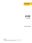
Connect the heater to the back of the controller using the socket labeled
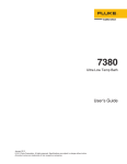
“HEATER”. Be sure the heater cable is adequate for the amount of current required and that the heater is wired correctly and safely. See Figure 1 on page 13
for heater wiring.
CONTROLLED SYSTEM
CONTROLLER
HEATER SOCKET
CUT-OUT
HOT
HEATER
10 A MAX
NEUTRAL
GROUND
Figure 1 Controller to Heater Wiring
4.3
Control Probe
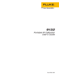
Connect the control probe into the socket at the back of the controller labeled
“PROBE” (see Figure 2 on page 14). Insert the probe into the bath or system to
be controlled. For best stability and response time the control probe should be
13
2200 Temperature Controller
User’s Guide
located in close proximity to the heater. Observe the maximum temperature rating of the probe and be careful it is not exceeded.
Rear Panel
Probe Connector
1
2
4
3
RTD Sensor
Figure 2 RTD Probe Wiring
Set the high limit (HL) less than or equal to the probe maximum temperature.
4.4
Power
CAUTION: Do not plug the instrument into 230V if the indicator window
of the power entry module reads 115V. This action will cause the fuses to
blow and may damage the instrument.
Plug the controller power cord into a mains outlet of the proper voltage, frequency, and current capability (see Section 2.1, Specifications on page 9). Insure that the indicator window of the power entry module matches the voltage
of the mains supply.
Turn the controller on using the rear panel "POWER" switch. The controller
will turn on and begin to heat or cool the system to reach the previously programmed temperature set-point. The front panel LED display will indicate the
actual process temperature. See Section 4.5, Fuses for information on selecting
the correct fuse for the application.
When powered on the control panel display will briefly show a four digit number. This number indicates the number of times power has been applied to the
unit. Also briefly displayed is data which indicates the controller hardware configuration. This data is used in some circumstances for diagnostic purposes.
14
4 Installation
Fuses
4.5
Fuses
CAUTION: Never use this instrument in a system that uses more power or
current as listed in Section 2.1, Specifications on page 9.
The controller is shipped from the factory with fast acting fuses rated for the
maximum capacity of the instrument.
If the controller is connected to a system which uses less than 10 amps, the
fuses will need to be changed in order to be correct for the system. Once the
controller is connected in the system, the system current needs to be measured
or calculated and the appropriate fuse size and characteristics selected. Generally, the fuse selected is rated at 125% of the maximum current of the system.
The time-current characteristics of the fuse are selected by the application.
Usually, fast acting fuses are selected systems without a high in-rush current,
i.e. "hot" calibration baths. Time-delay or slow blow fuses are selected for systems with a high in-rush current, i.e. "cold" calibration baths. Refer to the
fuseology section of your fuse catalog for help in determining fuse size and
characteristics or contact an Authorized Service Center (see Section 1.4) for assistance. Once the correct fuse characteristics and rating of the fuses have been
selected and the appropriate fuses placed in the power entry module of the instrument, mark the instrument so the user can visibly see the fuse size and rating for fuse replacement. Be sure to change both fuses to the new rating and
correct characteristic.
The controller uses 0.2 amps of current. This current should be taken into consideration when calculating the system power.
Example when using the power of the system:
P = Power of the system (Total Watts)
V = Nominal line voltage (115 VAC or 230 VAC)
I = Fuse current
I = 1.25 ×
P
0.9 × V
Example when using the system current:
I = System current
If = Fuse current rating
I f = 1.25 × I
15
5 Parts and Controls
Front Panel
5
5.1
Parts and Controls
Front Panel
The following controls and indicators are present: (1) the digital display, (2) the
control buttons. (see Figure 3)
(1) The digital display of the temperature controller displays the set and actual
temperatures and various controller functions, settings, and constants. The display shows temperatures in values according to the selected scale °C or °F.
(2) The control buttons (SET, DOWN, UP, and EXIT) are used to set the temperature set-point, access and set other operating parameters, and access and set
calibration parameters.
Setting the control temperature is done directly in degrees of the current scale.
The control temperature can be set to ten-hundredths of a degree Celsius.
The functions of the buttons are as follows:
SET – Used to display the next parameter in the menu and to set parameters to
the displayed value.
DOWN – Used to decrement the displayed value of parameters.
UP – Used to increment the displayed value.
Figure 3 Front Panel
17
2200 Temperature Controller
User’s Guide
EXIT – Used to exit from a menu. When EXIT is pressed any changes made to
the displayed value will be ignored.
5.2
Back Panel
The following features are found on the rear panel of the controller: (1) the
power entry module, (2) the heater power connector, (3) the control probe input
connector, and (4) the RS-232 interface connector (see Figure 4).
(1) The power entry module includes: (A) the IEC power line connector, (B)
the ON/OFF switch, (C) the voltage selector with indicator window and two
fuses. The unit is shipped from the factory with fuses as listed in the specifications (Section 2.1 on page 9). Additional information on fuse usage is in Section 4.5.
(A) The appropriate power cord with IEC connector has been included
with the controller for the voltage specified in the order.
(B) The double pole single throw (DPST) power switch indicates the
ON/OFF positions with the universal I/O.
WARNING: The output voltage to the heater socket (item 2 in Figure 4) is
the same as the input voltage of the power entry module (item 1 in Figure
4).
Figure 4 Back Panel
18
5 Parts and Controls
Back Panel
(C) The power entry module is provided with a dual voltage selector integrated into the fuse holder. The controller has been specially designed to
allow either 115 or 230 VAC operation. The voltage indicator window notifies the user of the voltage selected. See Figure 4.
Two fuses are contained in the internal fuse holder. The fuse holder will accept
either 1/4" x 1 1/4" or 5 x 20 mm fuses. Access to the fuses and the voltage selector is obtained by placing a flathead screwdriver in the slot at the top of the
power entry module and opening the module front panel.
WARNING: Access to the fuses may not be obtained with the power cord
plugged into the IEC power line connector.
WARNING: The output voltage to the heater socket (item 2 in Figure 4) is
the same as the input voltage of the power entry module (item 1 in Figure
4).
(2) The heater socket is the source of controlled power for the system heater.
This power is switched by the solid-state relay to maintain a constant temperature. The voltage is the same as that supplied through the entry module (A). For
a diagram of how to wire the heater to the controller see Figure 1 on page 13.
An extra line cord has been included with the unit for use with the heater
socket.
(3) The control probe is plugged in here. The probe is a DIN 43760 type RTD.
Probes or additional connectors for use with the user’s probes are available
from Hart. For assistance in wiring an RTD to the controller see Figure 2 on
page 14. A probe connector has been provided for use with the control probe
connection.
(4) The RS-232 communications cable is connected to this 9 pin D-subminiature connector. This enables the controller to be programmed and operated
remotely.
(5) The serial number label (not shown) is located on the bottom of the unit towards the back panel.
19
6 General Operation
Control System
6
6.1
General Operation
Control System
The 2200 temperature controller is not specified for use with a particular system. Its flexibility enable it to be used with a large variety of control systems.
Often the controller is used with a precision constant temperature bath.
It is the responsibility of the user to ensure that the components are chosen and
the system constructed to ensure safe and proper operation of the complete system. The user should have a good knowledge of and experience with, electrical
fundamentals and wiring practices as well as control systems. Hart Scientific
cannot be responsible for any damages or injury resulting from improper design or operation of the control system. For more help or information, contact
an Authorized Service Center.
6.2
Temperature Controller
The system temperature is controlled by Hart Scientific’s unique hybrid digital/analog temperature controller. The controller offers the tight control stability
of an analog temperature controller as well as the flexibility and programmability of a digital controller.
The temperature is monitored with a platinum resistance sensor as the control
probe. The signal is electronically compared with the programmable reference
signal, amplified, and then passed to a pulse-width modulator circuit which
controls the amount of power applied to the heater.
WARNING: For protection against solid-state relay failure or other circuit failure, a bi-metallic cut-out should be used.
The controller allows the operator to set the set-point temperature with high
resolution, adjust the proportional band, monitor the heater output power, and
program the controller configuration and calibration parameters. The controller
may be operated in temperature units of degrees Celsius or Fahrenheit. The
controller is operated and programmed from the front control panel using the
four key switches and digital LED display. The controller is equipped with an
RS-232 serial digital interface for remote operation. Operation of the controller
using the front control panel is discussed following in Section 7. Operation using the digital interface is discussed in Section 8.
When the controller is set to a new set-point the system will heat or cool to the
new temperature. There may be a small overshoot or undershoot of about 0.5°C
or more depending on the system and proportional band.
21
7 Controller Operation
Process temperature
7
Controller Operation
This chapter discusses in detail how to operate the temperature controller using
the front control panel. Using the front panel key switches and LED display the
user may monitor the process temperature, set the temperature set-point in degrees C or F, monitor the heater output power, adjust the controller proportional
band, and program the probe calibration parameters, operating parameters, and
serial interface parameters. Operation of the functions are shown in the
flowchart summarized in Figure 5.
7.1
Process temperature
The digital LED display on the front panel allows direct viewing of the process
temperature. This temperature value is what is normally shown on the display.
The units, C or F, of the temperature value are displayed at the right. For
example,
25.00 C
Process temperature in degrees Celsius
The temperature display function may be accessed from any other function by
pressing the “EXIT” button.
7.2
Temperature Set-point
The temperature can be set to any value within the range as given in the specifications with a high degree of resolution. The temperature range of the particular fluid used in a bath must be known by the operator and the bath should only
be operated well below the upper temperature limit of the liquid. In addition,
the high level set-point should also be set below the upper limit of the fluid.
Setting the temperature involves two steps: (1) select the set-point memory, (2)
adjust the set-point value
7.2.1
Programmable Set-points
The controller stores 8 set-point temperatures in memory. The set-points can be
quickly recalled to conveniently set the system to a previously programmed
temperature.
To set the temperature one must first select the set-point memory. This function
is accessed from the temperature display function by pressing “SET”. The
number of the set-point memory currently being used is shown at the left on the
display followed by the current set-point value.
25.00 C
S
Process temperature in degrees Celsius
Access set-point memory
23
2200 Temperature Controller
User’s Guide
Figure 5 Controller Operation Flowchart
24
7 Controller Operation
Temperature Scale Units
1.
25.
Set-point memory 1, 25.°C currently used
To change the set-point memory press “UP” or “DOWN”.
U
4.
Increment memory
40.
New set-point memory 4, 40.°C
Press “SET” to accept the new selection and access the set-point value.
S
7.2.2
Accept selected set-point memory
Set-point Value
The set-point value may be adjusted after selecting the set-point memory and
pressing “SET”.
40.00
Set-point value
If the set-point value need not be changed then press “EXIT” to resume displaying the probe temperature. To adjust the set-point value press “UP” or
“DOWN”.
U
Increment display
42.50
New set-point value
When the desired set-point value is reached press “SET” to accept the new
value and access the temperature scale units. If “EXIT” is pressed, any changes
made to the set-point are ignored.
S
7.3
Accept new set-point value
Temperature Scale Units
The temperature scale units of the controller may be set by the user to degrees
Celsius (°C) or Fahrenheit (°F). The units will be used in displaying the process
temperature, set-point, and proportional band.
The temperature scale units selection is accessed after the set-point adjustment
function by pressing “SET”. From the temperature display function access the
units selection by pressing “SET” 3 times.
25.00 C
S
Process temperature
Access set-point memory
25
2200 Temperature Controller
User’s Guide
1.
S
25.
Access set-point value
25.00
S
Set-point memory
Set-point value
Access scale units selection
Un= C
Scale units currently selected
Press “UP” or “DOWN” to change the units.
U
Change units
Un= F
New units selected
Press “SET” to accept the new selection and access the scan.
S
7.4
Set the new units and access the scan
Scan
The scan rate can be set and enabled so that when the set-point is changed the
controller allows heating or cooling at a specified rate (degrees per minute) until it reaches the new set-point. With the scan disabled the controller allows
heating or cooling at the maximum possible rate.
7.4.1
Scan Control
The scan is controlled with the scan on/off function that appears in the main
menu after the temperature scale units.
Sc=OFF
Scan function off
Press “UP” or “DOWN” to toggle the scan on or off.
Sc=On
Scan function on
Press “SET” to accept the present setting and continue.
S
26
Accept scan setting
7 Controller Operation
Set-point Resistance
7.4.2
Scan Rate
The next function in the main menu is the scan rate. The scan rate can be set
from .1 to 99.9°C/min. The maximum scan rate however is actually limited by
the natural heating or cooling rate of the instrument. This is often less than
100°C/min, especially when cooling.
The scan rate function appears in the main menu after the scan control function.
The scan rate units are in degrees per minute, degrees C or F depending on the
selected units.
Sr= 10.0
Scan rate in°C/min
Press “UP” or “DOWN” to change the scan rate.
Sr= 2.0
New scan rate
Press “SET” to accept the new scan rate and continue.
S
7.5
Accept scan rate
Set-point Resistance
The set-point resistance is used for calibrating the instrument. See Section9.
Pressing “SET” and “DOWN” simultaneously displays this value.
7.6
Secondary Menu
Functions which are used less often are accessed within the secondary menu.
The secondary menu is accessed by pressing “SET” and “EXIT” simultaneously and then releasing. The first function in the secondary menu is the
heater power display.
7.7
Heater Power
The temperature controller controls the temperature of the system by pulsing
the heater on and off. The total power being applied to the heater is determined
by the duty cycle or the ratio of heater on time to the pulse cycle time. By
knowing the amount of heating the user can tell if the system is heating up to
the set-point, cooling down, or controlling at a constant temperature. Monitoring the percent heater power lets the user know how stable the temperature is.
With good control stability the percent heating power should not fluctuate more
than ±1% within one minute.
The heater power display is accessed in the secondary menu. Press “SET” and
“EXIT” simultaneously and release. The heater power will be displayed.
S+ E
Access heater power in secondary menu
27
2200 Temperature Controller
User’s Guide
100.0 P
Heater power
To exit out of the secondary menu press “EXIT”. To continue on to the proportional band setting function press “SET”.
Return to temperature display
7.8
Proportional Band
In a proportional controller such as this the heater output power is proportional
to the process temperature over a limited range of temperatures around the
set-point. This range of temperature is called the proportional band. At the bottom of the proportional band the heater output is 100%. At the top of the proportional band the heater output is 0. Thus as the temperature rises the heater
power is reduced, which consequently tends to lower the temperature back
down. In this way the temperature is maintained at a fairly constant value.
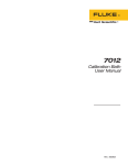
The temperature stability of the system depends on the width of the proportional band. See Figure 6. If the band is too wide the temperature will tend to
deviate excessively from the set-point due to varying external conditions. This
is because the power output changes very little with temperature and the controller cannot respond very well to changing conditions or noise in the system.
If the proportional band is too narrow the temperature may swing back and
forth because the controller overreacts to temperature variations. For best control stability the proportional band must be set for the optimum width.
The optimum proportional band width depends on several factors including
Figure 6 Various Proportional Band Settings
system heat transfer characteristics and heater-probe positioning. Thus the proportional band width may require adjustment for best stability when any of
these conditions change.
28
7 Controller Operation
Controller Configuration
The proportional band width is easily adjusted from the controller front panel.
The width may be set to discrete values in degrees C or F depending on the selected units. The optimum proportional band width setting may be determined
by monitoring the stability with a high resolution thermometer or with the controller percent output power display. Narrow the proportional band width to the
point at which the process temperature begins to oscillate and then increase the
band width from this point to 3 or 4 times wider.
The proportional band adjustment may be accessed within the secondary menu.
Press “SET” and “EXIT” to enter the secondary menu and show the heater
power. Then press “SET” to access the proportional band.
S+ E
100.0 P
S
Access heater power in secondary menu
Heater power
Access proportional band
Prop
Flashes “
” and then
59.00
displays proportional band setting
To change the proportional band press “UP” or “DOWN”.
D
Decrement display
59.50
New proportional band setting
To accept the new setting and access configuration menu press “SET”. Pressing
“EXIT” will exit the secondary menu ignoring any changes just made to the
proportional band value.
Accept the new proportional band setting
7.9
Controller Configuration
The controller has a number of configuration and operating options and calibration parameters which are programmable via the front panel. These are accessed from the secondary menu after the proportional band by pressing
“SET”. The display will prompt with “COnFIG”. Press “SET” once more.
There are 3 sets of configuration parameters — calibration parameters, operating parameters, and serial interface parameters. The menus are selected using
the “UP” and “DOWN” keys and then pressing “SET”. See Figure 5.
29
2200 Temperature Controller
User’s Guide
7.10
Calibration Parameters
CAUTION: Care should be exercised when adjusting these parameters as
they affect the accuracy of the set-point. This procedure is explained in detail in Section 9.
The calibration parameter menu is indicated by,
CAL
Calibration parameters menu
Press “SET” five times to enter the menu. The calibration parameters menu
contains the parameters, R0, ALPHA, DELTA, BETA, and the integral time adjustment which characterize the resistance-temperature relationship of the platinum control probe.
These parameters may be adjusted by an experienced user to improve the accuracy of the controller.
The calibration parameters are accessed by pressing “SET” after the name of
the parameter is displayed. The value of the parameter may be changed using
the “UP” and “DOWN” buttons. After the desired value is reached press “SET”
to set the parameter to the new value. Pressing “EXIT” will cause the parameter
to be skipped ignoring any changes that may have been made.
7.10.1
R0
This calibration parameter refers to the resistance of the control probe at 0°C.
The value of this parameter is set at the factory for best instrument accuracy.
7.10.2
ALPHA
This calibration parameter refers to the average sensitivity of the probe between
0 and 100°C. The value of this parameter is set at the factory for best instrument accuracy.
7.10.3
DELTA
This calibration parameter relates to the second order nonlinearity of the sensor.
The value of this parameter is set at the factory for best instrument accuracy.
7.10.4
BETA
This calibration parameter relates to the higher order nonlinearity of the sensor
below 0°C. The value of this parameter is set at the factory for best instrument
accuracy.
30
7 Controller Operation
Operating Parameters
7.10.5
Integral time adjustment
The integral time should be adjusted for the quickest settling time without causing instability. As a general rule, the optimum integral time is about 80% of the
period of the natural oscillation of the system.
7.11
Operating Parameters
The operator of the controller has access to setup constants. The correct values
are important for the safety of the system.
The operating parameters menu is indicated by,
Operating parameters menu
PAR
Press “SET” to enter the menu.
7.11.1
HL and LL
These parameters set the high and low set-point limits of the system. These parameters should not be set beyond the safe operating temperature limits of the
system.
From the “PAR” menu press “SET”.
High level set-point
HL
Press “SET” to adjust the high level set-point or press “EXIT” to access the low
level set-point.
S
Access high level set-point value
H= 800
D
Adjust the high level set-point
Decrement the high level set-point
H= 400
New high level set-point
When the desired high level set-point value is reached, press “SET” to accept
the new value and access the low level set-point.
S
LL
Low level set-point
Press “SET” to adjust the low level set-point or press “EXIT” to access the decimal place setting.
31
2200 Temperature Controller
User’s Guide
S
Access low level set-point value
L= -100
U
Adjust the low level se-point
Increment the low level set-point
L=- 50
New low level set-point
When the desired low level set-point value is reached, press “SET” to accept
the new value and access the decimal place setting.
S
7.11.2
DP (Decimal Place)
DP allows the user to set the decimal place on the display for one or two decimal places. DP defaults to two places.
Decimal place setting
dP
Press “SET” and then “UP” or “DOWN” to change the decimal place setting or
press “EXIT” to return to the beginning of the “PAR” menu.
S
Access decimal place setting
dP = 2
D
Adjust decimal place setting
Decrement the decimal place setting
dP = 1
New decimal place setting
Press “SET” to accept the new decimal place setting.
S
7.12
Serial Interface Parameters
The serial RS-232 interface parameters menu is indicated by,
SErIAL
Serial RS-232 interface parameters menu
The serial interface parameters menu contains parameters which determine the
operation of the serial interface. These controls only apply to controllers fitted
with the serial interface. The parameters in the menu are — BAUD rate, sample
period, duplex mode, and linefeed.
32
7 Controller Operation
Serial Interface Parameters
7.12.1
Baud Rate
The baud rate is the first parameter in the menu. The baud rate setting determines the serial communications transmission rate.
The baud rate parameter is indicated by,
bAUd
Serial baud rate parameter
Press “SET” to choose to set the baud rate. The current baud rate value is then
displayed.
2400 b
Current baud rate
The baud rate of the serial communications may be programmed to 300,
600,1200, 2400, 4800, or 9600 baud. Use “UP” or “DOWN” to change the
baud rate value.
4800 b
New baud rate
Press “SET” to set the baud rate to the new value or “EXIT” to abort the operation and skip to the next parameter in the menu.
7.12.2
Sample Period
The sample period is the next parameter in the serial interface parameter menu.
The sample period is the time period in seconds between temperature measurements transmitted from the serial interface. If the sample rate is set to 5, for instance, the controller transmits the current measurement over the serial
interface approximately every five seconds. The automatic sampling is disabled
with a sample period of 0. The sample period is indicated by,
SPer
Serial sample period parameter
Press “SET” to choose to set the sample period. The current sample period
value will be displayed.
SP= 1
Current sample period (seconds)
Adjust the value with “UP” or “DOWN” and then use “SET” to set the sample
rate to the displayed value.
SP= 60
7.12.3
New sample period
Duplex Mode
The next parameter is the duplex mode. The duplex mode may be set to full duplex or half duplex. With full duplex any commands received by the controller
33
2200 Temperature Controller
User’s Guide
via the serial interface will be immediately echoed or transmitted back to the
device of origin. With half duplex the commands will be executed but not echoed. The duplex mode parameter is indicated by,
dUPL
Serial duplex mode parameter
Press “SET” to access the mode setting.
d=FULL
Current duplex mode setting
The mode may be changed using “UP” or “DOWN” and pressing “SET”.
d=HALF
7.12.4
New duplex mode setting
Linefeed
The final parameter in the serial interface menu is the linefeed mode. This parameter enables (on) or disables (off) transmission of a linefeed character (LF,
ASCII 10) after transmission of any carriage-return. The linefeed parameter is
indicated by,
LF
Serial linefeed parameter
Press “SET” to access the linefeed parameter.
LF= On
Current linefeed setting
The mode may be changed using “UP” or “DOWN” and pressing “SET”.
LF= OFF
34
New linefeed setting
8 Digital Communication Interface
Serial Communications
8
Digital Communication Interface
The 2200 controller is capable of communicating with and being controlled by
other equipment through the digital interface. The RS-232 serial interface is
standard.
Hart recommends the use of shielded RS-232 cables for all remote
communication.
8.1
Serial Communications
The controller comes installed with an RS-232 serial interface that allows serial
digital communications over fairly long distances. With the serial interface the
user may access any of the functions, parameters and settings discussed in Section 7 with the exception of the BAUD rate setting. The serial interface operates
with 8 data bits, 1 stop bit, and no parity.
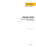
8.1.1
Wiring
The serial communications
cable attaches to the controller through the DB-9 connector on the back panel.
Figure 7 shows the pin-out
of this connector and suggested cable wiring. To eliminate noise, the serial cable
should be shielded with low
resistance between the connector (DB-9) and the shield.
8.1.2
Setup
Before operation, the serial
interface must first be set up
by programming the BAUD
rate and other configuration
parameters. These parameters are programmed within
the serial interface menu.
To enter the serial parameter
programming mode first
press “EXIT” while pressing
“SET” and release to enter
the secondary menu. Press
“SET” repeatedly until the
display reads “ProbE”.
Figure 7 Serial Cable Wiring
35
2200 Temperature Controller
User’s Guide
Press “UP” repeatedly until the serial interface menu is indicated with “SErIAL”. Finally press “SET” to enter the serial interface parameters menu. In
the serial interface parameters menu are the BAUD rate, sample rate, duplex
mode, and linefeed parameters.
8.1.2.1
Baud Rate
The baud rate is the first parameter in the menu. The display prompts with the
baud rate parameter by showing “BAUd”. Press “SET” to choose to set the
baud rate. The current baud rate value is displayed. The baud rate of the serial
communications may be programmed to 300, 600, 1200, 2400, 4800, or 9600
baud. The baud rate is pre-programmed to 2400 baud. Use “UP” or “DOWN”
to change the baud rate value. Press “SET” to set the baud rate to the new value
or “EXIT” to abort the operation and skip to the next parameter in the menu.
8.1.2.2
Sample Period
The sample period is the next parameter in the menu and prompted with
“SPer”. The sample period is the time period in seconds between temperature
measurements transmitted from the serial interface. If the sample rate is set to
5, for instance, the controller transmits the current measurement over the serial
interface approximately every five seconds. The automatic sampling is disabled
with a sample period of 0. Press “SET” to choose to set the sample period. Adjust the period with “UP” or “DOWN” and then use “SET” to set the sample
rate to the displayed value.
8.1.2.3
Duplex Mode
The next parameter is the duplex mode indicated with “dUPL”. The duplex
mode may be set to half duplex (“HALF”) or full duplex (“FULL”). With full
duplex any commands received by the bath via the serial interface will be immediately echoed or transmitted back to the device of origin. With half duplex
the commands will be executed but not echoed. The default setting is full duplex. The mode may be changed using “UP” or “DOWN” and pressing “SET”.
8.1.2.4
Linefeed
The final parameter in the serial interface menu is the linefeed mode. This parameter enables (“On”) or disables (“OFF”) transmission of a linefeed character (LF, ASCII 10) after transmission of any carriage-return. The default setting
is with linefeed on. The mode may be changed using “UP” or “DOWN” and
pressing “SET”.
8.1.3
Serial Operation
Once the cable has been attached and the interface set up properly the controller immediately begins transmitting temperature readings at the programmed
rate. The serial interface operates with 8 data bits, 1 stop bit, and no parity. The
set-point and other commands may be sent to the controller via the serial interface. The interface commands are discussed in Section8.2. All commands are
36
8 Digital Communication Interface
Interface Commands
ASCII character strings terminated with a carriage-return character (CR, ASCII
13).
8.2
Interface Commands
The various commands for accessing the controller functions via the digital interface are listed in this section (see Table 2). All commands are terminated
with a carriage-return character. The interface makes no distinction between
upper and lower case letters, hence either may be used. Commands may be abbreviated to the minimum number of letters which determines a unique command. A command may be used to either set a parameter or display a parameter
depending on whether or not a value is sent with the command following a “=”
character. For example “s”<CR> will return the current set-point and
“s=50.00”<CR> will set the set-point (set-point 1) to 50.00 degrees.
In the following list of commands, characters or data within brackets, “[” and
“]”, are optional for the command. A slash, “/”, denotes alternate characters or
data. Numeric data, denoted by “n”, may be entered in decimal or exponential
notation. Characters are shown in lower case although upper case may be used.
Spaces may be added within command strings and will simply be ignored.
Backspace (BS, ASCII 8) may be used to erase the previous character. A terminating CR is implied with all commands.
37
2200 Temperature Controller
User’s Guide
Table 2 Interface Commands
Command
Format
Command
Example
Returned
Returned
Example
Read current set-point
s[etpoint]
s
set: 9999.99 {C or F}
set: 150.00 C
Set current set-point to n
s[etpoint]=n
s=350
Read temperature
t[emperature]
t
t: 9999.9 {C or F}
t: 55.6 C
Read temperature units
u[nits]
u
u: x
u: c
Set temperature units:
u[nits]=c/f
Command Description
Acceptable
Values
Display Temperature
Set temperature units to Celsius u[nits]=c
Instrument
Range
C or F
u=c
u[nits]=f
u=f
Read scan mode
sc[an]
sc
Set scan mode
sc[an]=on/off
sc=on
Read scan rate
sr[ate]
sr
Set scan rate
sr[ate]=n
sr=1.1
Read proportional band setting
pr[opband]
pr
Set proportional band to n
pr[opband]=n
pr=8.83
Read heater power
(duty cycle)
po[wer]
po
po: 999.9
po: 1.0
r
r0: 999.999
r0: 100.578
Set temperature units to
Fahrenheit
sc: on
ON or OFF
srat: 99.9 {Cor F}/min
srat:10.0 C/min
.1 to 99.9
Secondary Menu
pb: 999.9
pb: 15.9
Depends on
Configuration
Configuration Menu
Cal Menu
Read R0 calibration parameter
r[0]
Set R0 calibration parameter to n r[0]=n
r=100.324
Read ALPHA calibration
parameter
al
al[pha]
Set ALPHA calibration parameter al[pha]=n
to n
al=0.0038433
Read DELTA calibration
parameter
de[lta]
de
Read DELTA calibration
parameter
de[lta]=n
de=1.3742
98.0 to 104.9
al: 9.9999999
al: 0.0038573
.002 to .006
de: 9.999
de: 1.507
0–3.0
Operating Parameters Menu
Read high level set-point
hl
hl
Set high level set-point
hl=n
hl=100
Read low level set-point
ll
ll
Set low level set-point
ll=n
ll= –50
Read decimal place
dp
dp
38
hl:999
hl:800
100 to 800
ll:999
ll: –100
–100 to 0
dp: 9
dp: 1
8 Digital Communication Interface
Interface Commands
Interface Commands continued
Command Description
Command
Format
Command
Example
Set decimal place
dp=n
dp=1
Returned
Returned
Example
Acceptable
Values
1 or 2
Serial Interface Menu
Read serial sample setting
sa[mple]
sa
Set serial sampling setting to n
seconds
sa[mple]=n
sa=0
Set serial duplex mode:
du[plex]=f[ull]/h[alf]
Set serial duplex mode to full
Set serial duplex mode to half
Set serial linefeed mode:
sa: 9
sa: 1
0 to 999
FULL or HALF
du[plex]=f[ull]
du=f
du[plex]=h[alf]
du=h
ON or OFF
lf[eed]=on/of[f]
Set serial linefeed mode to on
lf[eed]=on
lf=on
Set serial linefeed mode to off
lf[eed]=of[f]
lf=of
Calibration Menu
Read firmware version number
*ver[sion]
*ver
ver.9999,9.99
Read structure of all commands
h[elp]
h
list of commands
Legend:
ver.9141,1.21
[] Optional Command data
{} Returns either information
n Numeric data supplied by user
9 Numeric data returned to user
x Character data returned to user
Note:
When DUPLEX is set to FULL and a command is sent to READ, the command is returned followed by a
carriage return and linefeed. Then the value is returned as indicated in the RETURNED column.
39
9 Calibration Procedure
Single Point Calibration
9
9.1
Calibration Procedure
Single Point Calibration
For a quick calibration to a single point, R0 may be adjusted by itself without
any calculations. If the system is reading high, adjust R0 in the calibration
menu higher by small increments until the temperature of the system is correct.
NOTE: This method may cause other temperature settings to be off by a
degree or two.
9.2
Three Point Calibration Procedure
In some instances the user may want to calibrate the controller to improve the
temperature set-point accuracy. Calibration is done by adjusting the controller
probe calibration constants R0 and ALPHA so that the process temperature, as
measured with a standard thermometer, agrees more closely with the set-point.
The thermometer used must be able to measure the temperature with higher accuracy than the desired accuracy of the system.
1. Choose three set-points to use in the calibration of the R0, ALPHA, and
DELTA parameters.
2. Set the controller to the low set-point. When the calibrator reaches the
set-point and is stable, wait 15 minutes or so and then take a reading from the
thermometer. Sample the set-point resistance by holding down the SET key and
pressing the DOWN key. Write these values down as T1 and R1 respectively.
3. Repeat step 2 for the other two set-points recording them as T2, R2, T3, and
R3 respectively.
4. Using the recorded data, calculate new values for R0, ALPHA, and DELTA
parameters using the equations given below:
9.2.1
Compute DELTA:
A = T3 − T2
B = T2 − T1
T ⎤ ⎡ T ⎤⎡
T ⎤
⎡ T ⎤⎡
C = ⎢ 3 ⎥⎢1 − 3 ⎥ − ⎢ 2 ⎥⎢1 − 2 ⎥
⎣100 ⎦⎣ 100 ⎦ ⎣100 ⎦⎣ 100 ⎦
T ⎤ ⎡ T ⎤⎡
T ⎤
⎡ T ⎤⎡
D = ⎢ 2 ⎥⎢1 − 2 ⎥ − ⎢ 1 ⎥⎢1 − 1 ⎥
100
100
100
100
⎣
⎦⎣
⎦ ⎣
⎦⎣
⎦
E = R3 − R2
41
2200 Temperature Controller
User’s Guide
F = R2 − R1
delta =
AF − BE
DE − CF
T1-3 - Measured temperature using thermometer.
R1-3 - Value of R from display of 2200 (Press SET and DOWN at the same
time.)
where
T1 and R1 are the measured temperature and resistance at 50.0 °C
T2 and R2 are the measured temperature and resistance at 250.0 °C
T3 and R3 are the measured temperature and resistance at 450.0 °C
9.2.2
Compute R0 & ALPHA:
T ⎤
⎡ T ⎤⎡
a1 = T1 + delta ⎢ 1 ⎥⎢1 − 1 ⎥
⎣100 ⎦⎣ 100 ⎦
T ⎤
⎡ T ⎤⎡
a3 = T3 + delta ⎢ 3 ⎥⎢1 − 3 ⎥
100
100
⎣
⎦⎣
⎦
rzero =
alpha =
R3 a1 − R1 a3
a1 − a3
R1 − R3
R3 a1 − R1 a3
delta is the new value of DELTA computed above
5. Program the new values for DELTA (delta), R0 (rzero) and ALPHA (alpha)
into the calibrator with the following steps.
1. Press SET and EXIT keys at the same time and then press SET until R0
is displayed.
2. Press SET then use the UP or DOWN keys until the correct numerical
setting is displayed. Press SET to accept the new value.
3. Repeat step 2 for ALPHA and DELTA.
42
9 Calibration Procedure
Three Point Calibration Procedure
9.2.3
Accuracy & Repeatability
1. Check the accuracy of the calibrator at various points over the calibrated
range.
2. If calibrator does not pass specification at all set-points, repeat the Calibration Procedure.
43
10 Troubleshooting
10
Troubleshooting
This section contains information on troubleshooting and CE Comments
10.1
Troubleshooting Problems, Possible Causes,
and Solutions
In the event that the instrument appears to function abnormally, this section
may help to find and solve the problem. Several possible problem conditions
are described along with likely causes and solutions. If a problem arises, please
read this section carefully and attempt to understand and solve the problem. If
the problem cannot otherwise be solved, contact an Authorized Service Center
for assistance (see Section 1.4). Be sure to have the model number and serial
number of your instrument available.
Problem
Possible Causes and Solutions
Incorrect temperature
reading
Incorrect R0 parameter. Find the value for R0 on the Report of Test that was
shipped with the instrument (or from subsequent calibrations of the instrument). Reprogram the parameter into the controller (see Section 7.10.1, R0).
Allow the instrument to stabilize and verify the accuracy of the temperature
reading.
Controller locked up. The controller may have locked up due to a power
surge or other aberration. Initialize the system by performing the Factory Reset
Sequence.
Factory Reset Sequence. Hold the SET and EXIT buttons down at the same
time while powering on the instrument. After the instrument displays -init-,
release the buttons. The display shows -init-, then displays 2200, and then
displays the firmware version. After performing the master reset sequence, all
of the configuration parameters are reset to their default values. Reprogram
the R0 parameter into the controller (see Section 7.10.1, R0) and any other applicable configuration parameters. Allow the instrument to stabilize and verify
the accuracy of the temperature reading.
Blank display after mains
power applied
Blown fuse. A fuse may have blown due to a power surge or failure of a component. Replace the fuse once. If the fuse blows a second time, it is likely
caused by the failure of a component. Always replace the fuse with one of the
same rating, voltage, and type. Never replace the fuse with one of a higher current rating.
The Instrument heats or
cools too quickly or too
slowly
Incorrect scan and scan rate settings. The scan and scan rate settings may
be set to unwanted values. Check the Scan and Scan Rate settings. The scan
may be off (if the unit seems to be responding too quickly). The scan may be
on with the Scan Rate set low (if unit seems to be responding too slowly).
45
2200 Temperature Controller
User’s Guide
Problem
Possible Causes and Solutions
The display shows any of
the following: err 1 ,
err 2 , err 3 , err
4 , or err 5
Controller problem. The error messages signify the following problems with
the controller.
Err 1 - a RAM error
Err 2 - a NVRAM error
Err 3 - a Structure error
Err 4 - an ADC setup error
Err 5 - an ADC ready error
Initialize the system by performing the Factory Reset Sequence describe
above.
The display shows err
6
Defective control sensor. The control sensor may be shorted, open or otherwise damaged. Disconnect the control sensor from the instrument. Measure
the resistance of the control sensor. The resistance between pins 2 and 3
should be 1-2 ohms. The resistance between pins 1 and 4 should be 1-2 ohms.
The resistance between pins 1 or 4 and 2 or 3 should be approximately 110
ohms at room temperature (25 °C). If it measures close to this, re-connect the
sensor, and reapply power to the instrument. If the error message returns,
there is a problem with the controller.
10.2
CE Comments
10.2.1
EMC Directive
Hart Scientific’s equipment has been tested to meet the European Electromagnetic Compatibility Directive (EMC Directive, 89/336/EEC). Selection of Light
Industrial or Heavy Industrial compliance has been based on the intended use
of the instrument. Units designed for use in a calibration laboratory have been
tested to Light Industrial Standards. Units designed to be used in the “field”
have been tested to both Light Industrial and Heavy Industrial Standards. The
Declaration of Conformity for your instrument lists the specific standards to
which the unit was tested.
10.2.2
Low Voltage Directive (Safety)
In order to comply with the European Low Voltage Directive (73/23/EEC),
Hart Scientific equipment has been designed to meet the IEC 1010-1 (EN
61010-1) and IEC 1010-2-010 (EN 61010-2-010) standards.
46