1
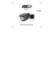
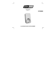
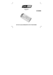
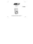
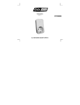
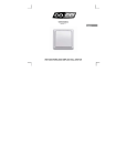
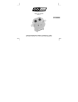
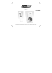
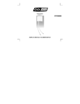
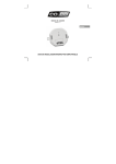
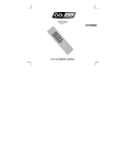
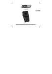
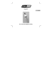
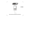
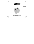
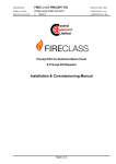
USER’S MANUAL
version 1.1
English
ACM-1000 BUILT-IN SWITCH
ACM-1000 BUILT-IN SWITCH
A
B
C
D
*
E
F
A: Search mode button
B: Indicator (voltage and connection status)
C: Fuse holder
D: Terminal screws
E: Mounting tabs
F: Power connection
* Picture of the AYCT-102
(not included)
1
ACM-1000 BUILT-IN SWITCH
A
[3]
B
[5]
[2A] Wall installation: Remove the wires connected
to the existing simplex switch. Continue with step
[3].
The existing wall switch is replaced by this
product and is no longer used!
[2B] Ceiling installation: Remove the existing
lighting and disconnect the two wires attached to
the lighting. Continue with step [5].
[1] Switch off the mains power (in meter
cupboard).
2
ACM-1000 BUILT-IN SWITCH
1
3
2
A
A
4
[7]
[3] Connect the two disconnected wires to the two
leftmost terminals: [1] the (brown) “hot wire”, [2]
the (black) “switch wire”. Tighten the clamping
screws.
[4] Connect a (blue) neutral wire from the wall to
one of the two rightmost terminals [3] or [4]. It does
not matter which one you choose. Continue with
step [7].
The existing switch must be a 2-way switch
(not a 3-way switch for control from two locations)!
Your wire colours may be different! If in doubt,
ask your installer!
In practice, there is often no neutral wire
present for a 2-way switch. If not, one must be
installed!
3
ACM-1000 BUILT-IN SWITCH
1
4
2 3
B
B
[5] Attach the disconnected wires from the ceiling
to the two outermost terminals (IN): [1] the (brown)
“hot wire”, [4] the (blue) “neutral wire”. Tighten the
clamping screws.
[6] Attach the two wires from the lighting to the two
innermost connections (OUT) [2] and [3]. Tighten
the clamping screws.
It does not matter which wire is connected to [2]
and which is connected to [3]!
Your wire colours may be different! If in doubt,
ask your installer!
4
ACM-1000 BUILT-IN SWITCH
[7] Switch on the mains power (in the meter
cupboard). The indicator on the switch remains lit
as long as there is power on the circuit.
[8] Briefly press the search mode button with a
pointed object. The indicator will begin to flash.
The search mode will be active for 15 seconds.
If necessary, repeat [8] to activate the search mode
again!
For the following steps: Be careful! Only touch
the plastic portion of the product! Do not contact
any exposed wiring!
5
ACM-1000 BUILT-IN SWITCH
2x
[10] To confirm, the built-in switch switches on and
off two times. The code of the transmitter is stored
in the memory of the receiver.
[9] Send an "on" signal with the transmitter; for
example: Press the desired on button of a COCO
remote control or wall switch, or activate a COCO
motion sensor. The indicator on the built-in switch
stops flashing as soon as the connection has
been made.
A maximum of 6 different transmitter codes can
be stored simultaneously.
See the manual for the concerned transmitter.
The pictured transmitter is not always included.
Check the specifications on the packaging!
6
ACM-1000 BUILT-IN SWITCH
A
B
A
B
[11A] Save the two screws so the built-in switch
can be mounted in the junction box if there is
enough room.
[12A] Cover the junction box with a blind cover
(available from your electrical retailer) once the
switch has been installed.
[11B] If there is too little room in the junction box,
break off the mounting tabs.
[12B] Mount the light on the ceiling (again) once
the switch has been installed.
7
ACM-1000 BUILT-IN SWITCH
Remarks
Reminders
• This product is intended for installation in a wall or ceiling junction box and must be used in combination
with at least one COCO transmitter.
• This product is a switch/receiver: control lights (or other suitable devices) remotely, without complicated
wiring.
• This product can be used for halogen lighting or other devices with a voltage lower than 230 Volts, if
they are equipped with a 230 Volt transformer. If in doubt, consult your lighting supplier or installer.
• To prevent interference, avoid placing multiple products close to each other. The minimum distance
between units should be approx. 50 cm.
• The wireless system can be expanded indefinitely with other COCO remote controls and/or receivers.
• Your COCO transmitter may have a special "group" button with which multiple receivers with different
settings can be controlled simultaneously. Repeat [8 - 10] and press the "group" button on the
transmitter during step [9].
• During a power failure the codes remain in the memory.
• To delete the stored codes (resetting the memory): (1) Hold in the search mode button. (2) The
indicator begins flashing after approx. 7 seconds. (3) Release the search mode button. (4) Briefly press
the search mode button again. (5) To confirm, the connected device switches on and off two times.
• If the product does not work:
- Reset the memory (see previous line) and set the code from the transmitter again (repeat [8 - 10]).
- Check whether the indicator is lit; if not, there may not be any power to the product or the fuse may
have blown.
- Fuse replacement: (1) Open the wall or ceiling junction box. (2) Pry open the fuse holder with a
screwdriver. (3) Press the fuse out of the holder (the fuse will be slightly blackened if it is blown). (4)
Press the new fuse into the holder. (5) Press the holder into the switch and close the wall or ceiling
junction box.
8
ACM-1000 BUILT-IN SWITCH
Safety instructions
• Always switch off the mains power before you begin with installation or removal. Switch the mains
power on again once you are completely finished with the installation/removal, unless stated otherwise.
• The connected voltage must be 220-240 Volts and 50 Hertz.
• Do not connect any lights or other devices that consume more than 1000 Watts.
• Connecting incorrect equipment can cause defects, a short circuit and fire.
• This product is protected with a 20 mm fuse rated at 5 A (T5A, H250V). An equivalent fuse must be
used during replacement.
• Do not expose this product to excessive heat, direct sunlight or moisture.
• Do not attempt to repair this product. If the product is damaged or if you are in doubt about the proper
operation, take the product back to the place of purchase.
• Do not use the product in damp areas. Clean the device with a clean cloth.
Wireless
• This product works using a radio signal that passes through walls, windows and doors. The range is
maximum 75 metres in the open air. The range indoors is strongly influenced by local conditions such
as concrete, glass and metals. On average, the indoor range is approximately 30 metres.
• New double glass often includes a thin metallic layer. This type of glazing (“HR glass”) allows most
visible light to pass through but has a negative impact on radio signals. If there is HR glass between the
transmitter and receiver, you should expect a significant reduction of the range of the wireless signal.
• This product operates at a frequency of 433.92 MHz. It complies with the essential requirements and
other conditions of R&TTE Directive 1999/5/EC and can be used in all EU countries.
• There may be restrictions on the use of this device outside the EU. If this device is used outside the EU,
check whether the device complies with the local directives.
This product complies with the essential requirements and other relevant provisions of the applicable
European directives. The Declaration of Conformity (DoC) is available at www.coco-technology.com.
9
ACM-1000 BUILT-IN SWITCH
If possible, submit this product for recycling after use. Do not dispose of the product with household trash.
Warranty and copyright
This device is covered by a 2-year warranty that begins on the day of purchase. Visit www.cocotechnology.com/warranty for additional information. Reprinting of (portions of) this manual without
permission from Pan-Trade International B.V. is expressly prohibited.
10
ACM-1000 BUILT-IN SWITCH
PAN-TRADE INTERNATIONAL B.V.
P.O. BOX 126
4760 AC ZEVENBERGEN
THE NETHERLANDS
www.coco-technology.com
Declaration of Conformity
Pan-Trade International BV declares that the COCO product, model:
type designation
item number
AC-1000 BUILT-IN SWITCH
74015
is in compliance with the essential requirements and other relevant provisions of directives R&TTE
1999/5/EC, EMC 2004/108/EC and LVD 2006/95/EC and is compatible with the standards EN 300 2201/3, EN 55015, EN 301 489-1/3 and EN 60950.
Manufacturer / Authorised representative,
M.A. Hoekstra, managing director
Zevenbergen, 2008-01-30
11