1
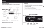
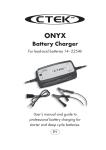
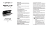
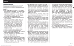
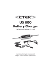
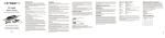
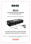
M200
Battery Charger
For lead-acid batteries
User Manual and Guide to professional
charging of starter and deep cycle batteries.
EN
INTRODUCTION
Congratulations on purchasing your new CTEK professional switch mode battery charger. This charger is part of a range of
professional battery chargers from CTEK SWEDEN AB. It represents the latest technology in battery charging with charging
and analysis in eight steps with temperature compensation. Read this User Manual and follow the instructions
carefully before using your new charger.
SAFETY
• The charger is designed for charging only batteries according to the
technical specification. Do not use the charger for any other purpose.
Always follow battery manufacturers’ user and safety recommendations.
• Never try to charge non-rechargeable batteries.
• Never place the charger on top of the battery or cover the charger
when charging.
• Never charge a frozen or damaged battery.
• Never charge a Li-battery with temperature below 0°C (32°F) if not
specified by the battery manufacturer.
• Never use a charger with damaged cables. Ensure that the cables have
not been damaged by hot surfaces, sharp edges or in any other way.
• Never place a fan-cooled charger so that dust, dirt or similar can be
sucked into the fan.
• A damaged cable must be replaced by a CTEK representative using an
original part supplied by CTEK. A detachable cable can be replaced by
the user using an original part supplied by CTEK.
• Connection to the mains supply must be in accordance with the national
regulations for electrical installations.
• Chargers with grounded mains plug must only be connected to a
grounded socket outlet.
• During charging, Lead-Acid batteries could emit explosive gases. Prevent sparks close to the battery. Provide for good ventilation.
• Chargers with IP-class lower than IPx4 are designed for indoor use. See
technical specification. Do not expose to rain or snow.
• Connect the charger to the battery´s positive pole and then to the negative pole. For batteries mounted inside a vehicle, connect the negative
connection to the vehicle chassis remote from the fuel pipe. Then connect the charger to mains supply.
• Disconnect the charger from the mains supply. Next remove the negative connection (vehicle chassis) and then the positive connection.
• Don’t leave any battery unattended for a longer period of time during
charging. If any error occurs disconnect the charger manually.
• (IEC 7.12 ed.5) This appliance is not intended for use by persons
(including children) with reduced physical, sensory or mental capabilities, or lack of experience and knowledge, unless they have been given
2 • EN
supervision or instruction concerning use of the appliance by a person
responsible for their safety. Children should be supervised to ensure that
they do not play with the appliance.
(EN 7.12) This appliance can be used by children aged from 8 years
and above and persons with reduced physical, sensory or mental capabilities, or lack of experience and knowledge if they have been given
supervision or instruction concerning use of the appliance in a safe way
and understand the hazards involved. Children shall not play with the
appliance. Cleaning and user maintenance shall not be made by children without supervision.
CHARGING
Connecting the charger to a battery fitted in a vehicle
1. The power cord should be disconnected when connecting or disconnecting the battery leads.
2. Identify the battery terminal that is grounded (connected to the chassis). The negative terminal is normally the grounded post.
3. Charging a negatively grounded battery. Connect the red cable to the positive terminal on the battery and the black cable to
good metal engine ground away from the battery. Ensure you do not connect the black cable to fuel lines or sheet-metal body
parts.
4. Charging a positively grounded battery. Connect the black cable to the negative terminal on the battery and the red cable to
good metal engine ground away from the battery. Ensure you do not connect the black cable to fuel lines or sheet-metal body
parts.
Connecting the charger to an out of vehicle battery:
1. The power cord should be disconnected when connecting or disconnecting the battery leads.
2. Connect the red cable to the positive terminal on the battery and the black cable to the negative terminal.
If the battery leads have been connected incorrectly, the reverse polarity protection system will ensure that neither the charger
nor the battery are damaged.
Start charging
1. Connect the charger´s AC cord to an AC Power Supply. The charger will indicate POWER, yellow indication lamp (B).
2. The lamp for completely discharged battery (1) will illuminate if the battery’s voltage is less than 12V.
3. Normal charging will be indicated by the following lights: completely discharged battery (1), bulk charging (2), absorption
charging (3) or maintenance charging (4). When the maintenance charging lamp illuminates the battery is fully charged.
Charging will start if the voltage drops. The charger can normally be connected for months. Reconditioning is indicated by the
lamp (5) illuminating.
4. If the battery leads have been connected incorrectly, the reverse polarity protection system will ensure that neither the
charger nor the battery are damaged.
5. If nothing happens. If the lamp indicating the setting and the power lamp remain lit but no other lamp illuminates, the
connection to the battery or chassis may be poor or the battery may be faulty. Another cause may be a lack of voltage in the
AC Power Supply. Begin by improving the connection between the battery and charger.
6. Charging can be stopped at any time by disconnecting the charger’s AC cord. Always disconnect the AC cord before
disconnecting the battery leads. When you stop charging a battery installed in a vehicle you should always disconnect the
battery lead from the chassis before disconnecting the other battery lead.
EN • 3
BATTERY TYPES AND SETTINGS
M200 can easily be set for different types of batteries or conditions. The following recommendations should, however, only be
seen as guidelines. Please consult the battery manufacturer for further instructions.
Settings are made by pressing the “MODE-button “ and stepping forward one press at a time until the required mode is
reached, the button is then released. After about 2 seconds the charger activates the selected mode. The selected mode is
saved in a memory in the charger and remains there even if the charger is disconnected from battery and mains.
NORMAL
NORMAL - Normal setting for wet batteries, maintenance free and for most Gel batteries. Some Gel batteries prefer a slightly lower charging voltage. Please consult the battery manufacturer when in doubt.
NIGHT
NIGHT – This mode is equal to NORMAL, but with reduced current. The built-in fan is disabled and the unit
is almost silent. The Unit returns automatically to NORMAL after 8 hours. To ensure that the charger restarts
in NIGHT mode in the event of a power failure the setting is stored in a memory. The indication shows
“NIGHT” even if the charger has returned to NORMAL mode to remind that the charger will start in NIGHT
mode next time.
RECOND
RECOND - This mode is used to recover deep discharged flooded batteries where you could expect a
stratified acid (high acid weight in the bottom, low on top). Check with battery manufacturer when in doubt.
Use this mode with care, because the high voltage will cause some water loss. 16V is normally no problem
for electronics in 12V system. Consult your supplier when in doubt. Life of light bulbs will be reduced at
higher voltage. Try to disconnect light from the battery during this phase. Maximum effect and minimum risk
for electronics is achieved by charging a disconnected battery.
CHARGING PHASES
M200 charges and analyses in eight fully automatic steps. M200 has three different operating modes, see Battery Types and
Settings.
The battery charger has an 8-step fully automatic charging cycle:
Desulphation
Desulphation with pulses recovers sulphated batteries. Indicates with lamp 1.
Soft start (Lamp 1)
Start mode for the charging cycle. The start phase continues until the battery’s terminal voltage has risen above the set limit, at
which point the charger switches to bulk charging. If the terminal voltage has not passed the voltage limit within the time limit,
the charger switches to fault mode (lamp 0) and discontinues the charging. If so, the battery is faulty or its capacity is too large.
Bulk (Lamp 2)
Main charge when 80% of charging takes place. The charger delivers maximum current until the terminal voltage has risen to
the set level. Bulk has a maximum time, at which point the charger automatically switches to Absorption.
Absorption (Lamp 3)
Complete charge up to virtually 100%. The terminal voltage is maintained at the set level. During this phase the current tapers
successively. Once the current has tapered to the set limit, this phase switches to being timed. If the total time for Absorption
exceeds the time limit the charger automatically switches to maintenance.
Analysis (Lamp 3)
Testing self-discharge. If self-discharge is too high, charging is discontinued and fault mode is indicated.
Maintenance charging - Float (Lamp 4)
Charging at constant voltage.
Maintenance charging - Pulse (Lamp 4)
Charging varies between 95% and 100% state of charge. The battery receives a pulse when the voltage drops and keeps the
battery in perfect condition when it is not in use. The charger can be connected for months at a time. The charger continuously
measures the terminal voltage to determine whether a charging pulse should be initiated. If the battery is loaded and/or the
battery’s terminal voltage drops the charger starts a charging pulse until the terminal voltage reaches the set level. The charging
pulse is then discontinued and the cycle is repeated infinitely. If the terminal voltage drops below a lower limit, the charger
automatically goes back to the beginning of the charging curve.
Recond (Lamp 5)
This mode is used to recover deeply discharged flooded batteries. Recondition of deep discharged batteries. The voltage
increases with reduced current for a limited time period. The higher voltage starts some gassing and mixing of the acid, which is
beneficial for both battery capacity and expected life. Note that the battery could emit explosive gas during Recond. Recond is
performed between Analysis and Maintenance.
4 • EN
INDICATORS
3
2
0
A
4
5
1
B
C
D
E
LampDescription
0Fault mode, the charging is discontinued. For fault causes, see below.
1
Start mode
2
Bulk charging
3
Absorption charging
4
Maintenance charging
5Recond, reconditioning of completely discharged batteries.
A
Charging without temperature compensation.
B
Mains voltage connected
C
Normal
D
Recond
ENight. Charging with reduced power and disabled fan for 8 hours.
Fault mode
The charger goes to fault mode in the following situations:
•The battery is connected with poles reversed to the charger's terminals.
•The charger’s analysis function has interrupted charging.
•The terminals on the charger are short-circuited after charging has started.
•The charger has been in start mode for more than 4 hours.
TEMPERATURE COMPENSATION
M200 has a sensor cable placed together with the battery cables. The units will automatically adjust the charging voltage if the
temperature deviates from +25°C. A high temperature lowers the voltage and freezing conditions is handled by higher voltage.
The temperature is best measured on or very close to the battery. Therefore always place the sensor as close to the battery
as possible when charging. The sensor cable could be prolonged or cut to length with the same functionality. Activated
temperature sensor will be indicated by a lit temperature sensor indicator lamp. The charging voltage is then adjusted to the
+25°C condition.
SPECIFICATION
Model
Voltage AC
Charging voltage
Charging current
Current, mains
Back Current Drain*
Current ripple**
Ambient temperature Cooling Charger type Battery types Battery capacity
Protection class Weight
1055
220–240VAC, 50–60Hz.
14.4V
15A max.
2.9A rms (at full charging current)
<2Ah per month
<4%
-20°C – +50°C Output power is automatically reduced at higher temperatures.
Fan
Eight-step, fully automatic
All types of 12V lead-acid batteries (WET, MF, AGM and GEL).
28–300Ah, up to 500Ah for maintenance.
IP44 (Outdoor use)***
1.4kg
*) Back current drain is the current that the charger drains from the battery if the AC cord is disconnected.
**) The quality of the charging voltage and charging current are very important. High current ripple heats the battery and ages
the positive electrode. High voltage ripple can damage other equipment connected to batteries. The battery chargers from
CTEK produces very high quality voltage and current with low ripple.
***) IP44 cannot be guaranteed if the charger is not positioned horizontally with the long side or top side turned up.
MAINTENANCE
The charger is maintenance-free. The charger must not be opened; doing so will invalidate the warranty. If the power cable is
damaged it must be replaced by CTEK or its authorized representative. The charger casing can be cleaned using a damp cloth
and mild cleaning agent. Remove the plug from the power socket before cleaning.
EN • 5
PROGRAM DESCRIPTION
Soft Start
Bulk
Absorption
Recovers a
sulphated battery
Tests the battery
condition
Bulk charge
Peak charge with
minimal fluid loss
Soft Start
Bulk
Absorption
Current (A)
Voltage (V)
Desulphation
M200 PARAMETERS
Mode
NORMAL
or
RECOND
Desulphation
YES
Max 4h or until the
15A for max 20h.
14.4V until 4h after
voltage reaches 12.6V. NIGHT Mode max 5A. the current dropped to
4.5A, max 16h.
Note: In NIGHT Mode the M200 operates in NORMAL Mode with reduced current and
disabled fan. The unit automatically returns to NORMAL after 8h.
6 • EN
Analysis
Recond
Float
Pulse
Tests whether the
battery retains
the energy
Reconditioning of
a drained battery
Maintenance for
maximum
performance
Maintenance for
maximum
battery life
Analysis
Recond
Float
Pulse
Warning indication if
voltage drops to 12.0V
in 3 minutes.
Max 15.8V and 3A
13.6V with max 15A
for 4h for deeply
for max 10 days.
discharged batteries.
Otherwise for 30
minutes (only in Recond
mode).
Pulse start at 12.9V,
max voltage 14.4V.
EN • 7
LIMITED WARRANTY
CTEK SWEDEN AB, Rostugnsv. 3, SE-776 70 VIKMANSHYTTAN, SWEDEN issues this limited warranty to the original
purchaser of this product. This limited warranty is not transferable and is only valid for non-commercial use. CTEK SWEDEN AB
warrants this unit for 5 years from the date of purchase against defect workmanship or material. It is the obligation of the
purchaser to forward the unit together with proof of purchase to the manufacturer or its representative with transportation cost
prepaid. This warranty is void if the unit is abused, handled carelessly or repaired by anyone other than CTEK SWEDEN AB or
its authorized representative. CTEK SWEDEN AB makes no warranty other than this limited warranty and expressly excludes
any implied warranty including any warranty for consequential damages. This is the only expressed limited warranty and
CTEK SWEDEN AB neither assumes nor authorizes anyone to assume or make any other obligation towards the product other
than this limited warranty.
SUPPORT
20010739D
Fore support and more information about CTEK products: www.ctek.com, [email protected], +46(0) 225 351 80. For latest revised
manual see www.ctek.com.
8 • EN