1
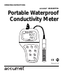
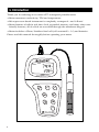
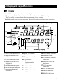
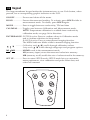
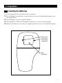
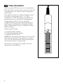
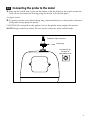
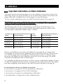
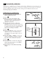
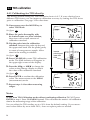
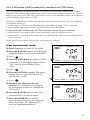
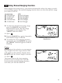
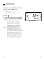
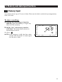
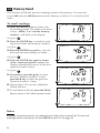
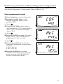
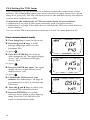
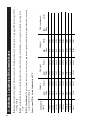
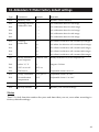
OPERATING INSTRUCTIONS
accumet® 13636AP75A
Portable Waterproof
Conductivity Meter
MEAS
READY
µS
C
ATC
ON
F
OF
DE
LD
HO
L
CA
AS
ME
MI
▲
MO
TER
EN
E
NG
RA
MR
▼
UP
SET
IP
67
Printed1/02
Table of Contents
1. Introduction............................................................................................4
2. Display and keypad functions .............................................................5-6
2.1 Display ...................................................................................................................................5
2.2 Keypad ...................................................................................................................................6
3. Preparation ..........................................................................................7-9
3.1 Inserting the batteries ..........................................................................................................7
3.2 Probe information ................................................................................................................8
3.3 Connecting the probe to the meter ....................................................................................9
4. Calibration .......................................................................................10-16
4.1 Important information on meter calibration .................................................................10
4.2 Preparing the meter for calibration .................................................................................11
4.3 Conductivity calibration..............................................................................................12-13
4.4 TDS calibration..............................................................................................................14-15
4.4.1 Calibrating for TDS directly ....................................................................................14
4.4.2 Calibration with conductivity standard and TDS factor ....................................15
4.5 Temperature calibration ...................................................................................................16
5. Measurement ...................................................................................17-22
5.1 Automatic Temperature Compensation (ATC) .............................................................17
5.2 Manual Temperature Compensation .........................................................................18-19
5.3 Taking measurements........................................................................................................20
5.4 Using manual ranging function.......................................................................................21
5.5 Hold function......................................................................................................................22
6. Memory and data input functions ..................................................23-24
6.1 Memory input .....................................................................................................................23
6.2 Memory recall .....................................................................................................................24
7. SETUP functions ...............................................................................25-40
7.1 Set Up mode overview.................................................................................................26-27
7.2 Program 1.0: Memory clear...............................................................................................28
7.3 Program 2.0: Viewing calibration data............................................................................29
7.4 Program 3.0: Viewing probe data ....................................................................................30
7.5 Program 4.0: Unit configuration .................................................................................31-34
P4.1: READY indicator and auto endpoint function.....................................................31
P4.2: Selecting °C or °F ......................................................................................................32
P4.3 Selecting Automatic or Manual Temperature Compensation.............................33
P4.4 Setting the TDS factor ...............................................................................................34
2
7.6 Program 5.0: Temperature ...........................................................................................35-36
P5.1 Adjusting the temperature coefficient ....................................................................35
P5.2 Adjusting the normalization temperature .............................................................36
7.7 Program 6.0: Selecting the cell constant..........................................................................37
7.8 Program 7.0: Setting the real-time clock....................................................................38-39
7.9 Program 8.0: Resetting to factory defaults .....................................................................40
8. Probe care and maintenance................................................................41
9. Troubleshooting....................................................................................42
10. Error Messages ....................................................................................43
11. Specifications ......................................................................................44
12. Addendum 1: Calibration tips ............................................................45
13. Addendum 2: Conductivity to TDS conversion factors ......................46
14: Addendum 3: Calculating TDS Conversion factors ............................47
15. Addendum 4: Calculating temperature coefficients..........................48
16. Addendum 5: Meter factory default settings ....................................49
3
1. Introduction
Thank you for selecting an accumet AP75 waterproof portable meter.
• Meter measures conductivity, TDS and temperature.
• Microprocessor-based instrument is completely waterproof—and it floats!
• Meter features a built-in real time clock, expanded memory, and many other userfriendly features, all of which are accessible through the membrane keypad.
• Meter includes a Ultem/Stainless Steel cell (cell constant K = 1.0) and batteries.
Please read this manual thoroughly before operating your meter.
MEAS
READY
µS
C
ATC
ON
F
OF
DE
LD
HO
L
CA
AS
ME
MI
▲
MO
TER
EN
E
NG
RA
MR
▼
UP
SET
4
2. Display and Keypad Functions
2.1
Display
The LCD has a primary and secondary display.
• The primary display shows the measured conductivity or TDS reading.
• The secondary display shows the temperature of the reading.
The display also shows error messages, keypad functions and program functions.
2.
1.
3.
4.
Primary display
5.
20.
6.
19.
7.
8.
18.
9.
17.
16.
10.
15. 14. 13. 12. 11.
1. SETup mode indicator
2. MEASurement mode
indicator
3. CALibration indicator
4. MEMory recall mode
indicator
5. millisiemens indicator
6. microsiemens indicator
7. parts per thousand
indicator
Secondary display
8. parts per million
indicator
9. Temperature indicator
10. Automatic
Temperature
Compensation
indicator
11. Clock indicator
12. ERRor indicator
13. MEMory location
indicator
14. Low battery indicator
15. Probe indicator
16. Calibration solution
indicator
16. Function ON/OFF
indicator
17. Cell constant
indicator
18. On/off indicator
19. HOLD indicator
20. READY indicator
5
2.2
Keypad
The large membrane keypad makes the instrument easy to use. Each button, when
pressed, has a corresponding graphic indicator on the LCD.
ON/OFF ................Powers and shuts off the meter.
HOLD ..................Freezes the measured reading. To activate, press HOLD while in
measurement mode. To release, press HOLD again.
MODE ..................Press to toggle between conductivity, TDS and time
CAL/MEAS ..........Toggles user between Calibration and Measurement mode.
NOTE: Temperature calibration is available from conductivity
calibration mode; see page 16 for directions.
ENTER/RANGE..ENTER function: Press to confirm values in Calibration mode
and to confirm selections in Setup mode.
RANGE function: Press to enter manual ranging function.
The MEAS indicator blinks while in manual ranging function.
▲
▼
..............Calibration mode: ▲ /▼ scrolls through calibration values.
Setup mode: ▲ /▼ scrolls through subgroups and program options.
................................MI/MR
work in the measurement mode.
MI
MR
MI (memory input) stores the measured value into memory.
MR (memory recall) recalls the sets of values stored in the memory.
SET UP..................Press to enter SETUP mode. SETUP mode lets you customize
meter preferences, view calibration and probe offset data, and
select cell constant.
6
3. Preparation
3.1
Inserting the Batteries
Four AAA batteries are included with your meter.
1. Use a Phillips screwdriver to remove the two screws holding the battery cover.
See figure below.
2. Lift off battery cover to expose batteries.
3. Insert batteries. Follow the diagram inside the cover for correct polarity.
4. Replace the battery cover into its original position. Screw cover back into place.
Remove these
two screws to
access battery
compartment
Battery
compartment
7
3.2
Probe information
Your accumet AP75 meter uses a conductivity/
TDS cell with a sturdy 6-pin connector. This cell
is designed for use with accumet waterproof
meters only.
Your meter includes an Ultem/Stainless Steel
cell with a cell constant of K = 1.0. This
conductivity/TDS cell features a built-in temperature sensor for Automatic Temperature
Compensation (ATC). It has a specially
designed housing that provides fast temperature response and reduces air bubble entrapment, which makes it easy to obtain accurate,
stable readings.
Wetted parts include:
1. Polyetherimide (Ultem)
2. Polybutylterphalate (Valox)
3. Stainless steel (SS 304)
NOTE: We recommend that the you do not submerse the probe above the protective yellow
cap. You can submerse the cable for brief periods of time, but not continuously.
See section 8 on page 41 for probe care and
maintenance information.
8
3.3
Connecting the probe to the meter
1. Line up the notch and 6 pins on the meter with the holes in the 6-pin connector.
Push down and turn the locking ring clockwise to lock into place.
See figure below.
2. To remove probe, turn the locking ring counterclockwise on the probe connector.
Pull probe away from the meter.
CAUTION: Do not pull on the probe cord or the probe wires might disconnect.
NOTE: Keep connectors clean. Do not touch connector with soiled hands.
Probe(with 6-pin connector)
locking ring
top view of 6-pin
connector of
temperature probe
9
4. Calibration
4.1
Important Information on Meter Calibration
Your meter has five measuring ranges. You can calibrate at one point in each of the
measuring ranges (up to five points). If you are measuring values in more than one
range, make sure to calibrate each of the ranges you are measuring.
To view current calibration points, see SETUP section Program 2.0 on page 29.
IMPORTANT: You need to calibrate your meter at a standard that is a minimum
of 20% of the range in which you are measuring. For example, use a minimum
calibration value of 400 µS in the 0 to 1999 µS range.
The following table lists the corresponding conductivity and TDS ranges. You
should calibrate each range using a solution that falls between the values in the
“recommended calibration solution range” column.
Conductivity
Range
Recommended Calibration
Solution Range
TDS
Range
Recommended Calibration
Solution Range
0.00-19.99 µS
6.00 to 17.00 µS
0.00-9.99 ppm
3.00 to 8.50 ppm
0.0-199.9 µS
60.0 to 170.0 µS
10.0-99.9 ppm
30.0 to 85.0 ppm
0-1999 µS
600 to 1700 µS
100-999 ppm
300 to 850 ppm
0.00-19.99 mS
6.00 to 17.00 mS
1.00-9.99 ppt
3.00 to 8.50 ppt
0.0-199.9 mS
60.0 to 170.0 mS
10.0-200 ppt
30.0 to 170 ppt
When you recalibrate your meter, old calibrations are replaced on a range basis.
For example, if you previously calibrated your conductivity meter at 1413 µS in the
0 to 1999 µS range and you recalibrate at 1500 µS (also in the 0 to 1999 µS range),
the meter will replace the old calibration data (1413 µS) in that range. The meter
will retain all calibration data in other ranges.
To completely recalibrate your meter, or when you use a replacement probe, it is best
to clear all calibration data in memory. To erase all old conductivity and TDS calibration data completely from memory, see SETUP section Program 8.0 on page 40.
For information on how to calibrate your meter:
• See section 4.3 on pages 12-13 for Conductivity Calibration.
• See section 4.3 on pages 14-15 for TDS Calibration.
• See section 4.4 on page 16 for Temperature Calibration.
• See Addendum 1 on page 45 for more calibration tips.
10
4.2
Preparing the Meter for Calibration
Before starting calibration, make sure you are in the correct measurement mode.
When you switch on the meter, the meter starts up in the units you shut it off in.
For best results, select a standard value close to the sample value you are measuring.
Alternatively use a calibration solution value that is approximately 2⁄3 the full scale
value of the measurement range you plan to use. For example, in the 0 to 1999 µS
conductivity range, use a 1413 µS solution for calibration.
Do not reuse calibration solutions after calibration. Contaminants in the solution can
affect the calibration, and eventually the accuracy of the measurements. Use fresh
calibration solution each time you calibrate your meter.
NOTE: These meters are factory set to a temperature coefficient of 2.1% per °C. For
most applications this will provide good results. See Program P5.1 on page
35 to set the temperature coefficient to a different value. See Addendum 3,
“Calculating Temperature Coefficients” on page 48 to determine the
appropriate temperature coefficient for your solution.
NOTE: The factory default value for normalization temperature is 25°C. If you need
to normalize to a value other than 25°C, see Program P5.2 on page 36.
11
4.3
Conductivity calibration
This meter is capable of up to 5-point conductivity calibration at one point per conductivity range (0.00-19.99 µS; 0.0-199.9 µS; 0-1999 µS; 0.00-19.99 mS; 0.0-199.9 mS).
All new calibration data will over-ride existing stored calibration data for each
measuring range you calibrate.
Calibrating for conductivity:
1. If necessary, press the MODE key to
select conductivity mode.
See figure A
2. Rinse the probe thoroughly with
de-ionized water or a rinse solution,
then rinse with a small amount of
calibration standard.
A
3. Dip the probe into the calibration
standard. Immerse the probe tip beyond
the upper steel band. Stir the probe gently
to create a homogeneous sample. Allow
time for the reading to stabilize.
Immerse
probe beyond
upper steel
band
See figure B
4. Press CAL/MEAS to enter conductivity
calibration mode. The CAL indicator
will appear in the upper right corner of
the display.
5. Press the MI/▲ or MR/▼ to change the
value on the primary display to match
the value of the calibration standard.
B
See figure C
6. Press ENTER to confirm the calibration
value. The meter returns to the MEAS
(measurement) mode.
7. Repeat steps 1-6 for other measuring
ranges.
C
12
Notes
When entering calibration mode, the meter will display the factory default value. If
the meter was previously calibrated, the display may “jump” to the factory default
value when switching from measurement to calibration mode.
To exit from Conductivity Calibration mode without confirming calibration, DO NOT
press ENTER in step 6. Press CAL/MEAS instead. This will retain the meter’s old calibration data in the measuring range of the calibration.
You can offset the conductivity reading up to ±20% from the default setting. If your
measured value differs by more than ±20%, clean or replace probe as needed.
13
4.4
TDS calibration
4.4.1 Calibrating for TDS directly:
The factory default setting for TDS conversion factor is 0.5. If your solution has a
different TDS factor, you can improve calibration accuracy by setting the TDS factor
prior to calibration. See page 34 for directions.
1. If necessary, press the MODE key to
select TDS mode.
See figure A
2. Rinse the probe thoroughly with
de-ionized water or a rinse solution,
then rinse with a small amount of
calibration standard.
A
3. Dip the probe into the calibration
standard. Immerse the probe tip beyond
the upper steel band. Stir the probe gently
to create a homogeneous sample. Allow
time for the reading to stabilize.
See figure
Immerse
probe beyond
upper steel
band
B
4. Press CAL/MEAS to enter TDS calibration
mode. The CAL indicator will appear in
the upper right corner of the display.
5. Press the MI/▲ or MR/▼ to change the
value on the primary display to match
the value of the calibration standard.
B
See figure C
6. Press ENTER to confirm the calibration
value. The meter returns to the MEAS
(measurement) mode.
7. Repeat steps 1-6 for other measuring
ranges.
C
Notes
To exit from TDS Calibration mode without confirming calibration, DO NOT press
ENTER in step 6. Press CAL/MEAS instead. This will retain the meter’s old calibration
data in the measuring range of the calibration.
You can offset the TDS reading up to ±20% from the default setting. If your measured value differs by more than ±20%, clean or replace probe as needed.
14
4.4.2 Calibration with Conductivity standard and TDS factor
The concentration of salts dissolved in solution increases the conductivity of that
solution. This relationship varies from salt to salt and is roughly linear over a given
range for a given salt. The TDS conversion factor is the number used by the meter to
convert from conductivity to TDS.
Instead of calibrating for TDS directly (described in section 4.4.1), you can calibrate
your meter meter by:
1. calibrating to conductivity standards (as described on pages 12-13) and then
2. entering the appropriate TDS conversion factor into the meter.
To determine the conductivity to TDS conversion factor for your solution:
• Addendum 2 on page 46 lists some commonly used conversion factors.
• Addendum 3 on page 47 describes how to calculate the TDS conversion factor for
other solutions.
Enter the TDS conversion factor into your meter as follows:
From measurement mode
1. Press Setup key to enter Set Up mode.
2. Press the ▲ and ▼ keys to scroll through
subgroups until you view parameter P4.0.
See figure A
3. Press the ENTER key five times to select
A
parameter 4.4. The upper display shows
“tdS” and the lower display shows
“P4.4”.
See figure B
4. Press the ENTER key again. The upper
display shows a value and the lower
display shows “tdS”.
B
See figure C
5. Calculate the TDS factor of your
solution. See Addendum 3 on page 47
for information on how to calculate the
TDS factor.
6. Press the ▲ and ▼ keys to select your
calculated TDS conversion factor.
7. Press the ENTER key to confirm
C
selection and to return to the subgroup
menu. Press the CAL/MEAS key to
return to measurement mode.
15
4.5
Temperature Calibration
Your probe features a built-in temperature sensor. The temperature sensor is factory
calibrated. Calibrate your sensor only if you suspect temperature errors that may
have occurred over a long period of time or if you have a replacement probe.
Temperature calibration
1. Make sure the cell is attached to the 6-pin
connector. The ATC annunciator will
appear at the right-hand side of the LCD*.
2. Switch the meter on. Press the MODE
key to select conductivity mode.
3. Press the CAL/MEAS key to enter conductivity or TDS calibration mode. The
CAL indicator appears above the primary
display.
See figure A
A
4. While in conductivity or TDS calibration
mode, press the MODE key to enter temperature calibration mode. The primary
display shows the current temperature
reading and the secondary display shows
the factory default temperature value.
See figure B
5. Dip the cell into a solution of known
temperature (i.e. a temperature bath).
Allow time for the built-in temperature
sensor to stabilize.
B
6. Scroll with the ▼ and ▲ keys to set
the correct temperature value (i.e. the
temperature of the temperature bath).
You can adjust the reading in increments
of 0.1°C.
See figure C
7. Once you have selected the correct
C
temperature, press the ENTER key.
8. Press the CAL/MEAS key to return to
conductivity or TDS measurement mode.
Notes
• You can offset the temperature reading up to ±5°C from the original reading.
• To exit this program without confirming the temperature calibration value, DO NOT
press ENTER in step 7. Press CAL/MEAS instead.
16
*If the ATC indicator does not light, see Program P4.3, on page 33 to switch it on.
5. Measurement
This meter is capable of taking measurements with automatic or manual temperature
compensation. Factory default is ATC on.
5.1
Automatic Temperature Compensation
For automatic temperature compensation
(ATC) simply plug the conductivity/TDS
probe into the meter (see page 9 for directions). The ATC indicator will light on the
LCD.
See figure A
Notes
A
If the ATC indicator does not light, manual
temperature compensation may be selected
in the meter’s Set Up mode. See Program
P4.3 on page 33 for directions on selecting
Automatic Temperature Compensation.
17
5.2
Manual Temperature Compensation
IMPORTANT: For manual compensation, you must deactivate the temperature
probe.
5.2.1 Selecting Manual Temperature Compensation
Select between Automatic Temperature Compensation (ATC) and Manual
Temperature Compensation in the Set Up Program P4.3. Meter default is ATC on.
From measurement mode
1. Press Setup key to enter Set Up
mode.
2. Press the ▲ and ▼ keys to scroll
through subgroups until you view
parameter P4.0.
See figure A
3. Press the ENTER key three times
A
to select parameter 4.3. The upper
display shows “ATC” and the lower
display shows “P4.3”.
See figure B
4. Press the ENTER key again. The
upper display shows “ATC” and the
lower display shows “YES” or “NO”.
See figure C
B
5. Press the ▲ and ▼ keys to select
the Automatic Temperature
Compensation feature on of off.
• YES = ATC on
• NO = ATC off
6. Press the ENTER key to confirm
selection and to return to the subgroup menu. Press the CAL/MEAS
key to return to measurement mode.
18
C
5.2.2 Setting a manual temperature compensation value
To use manual temperature compensation, you need to enter the temperature value
of your process into the meter. This is the value at which readings will manually
temperature compensate. You can select any temperature between 0 and 100°C
(32 and 212°F). Default value is 25°C.
To select a manual temperature
compensation value:
1. Switch the meter on. Press the MODE
key to select measurement mode.
2. If necessary, select ATC off as described
in section 5.2.1 on page 18. The ATC
indicator will not appear on the display.
3. Press the CAL/MEAS key to enter
conductivity or TDS calibration mode.
The CAL indicator will appear above the
primary display.
D
See figure D
4. While in conductivity or TDS calibration
mode, press the MODE key to enter temperature calibration mode. The primary
display shows the current temperature
setting and the secondary display shows
the default value 25°C (77°F).
See figure
E
E
5. Check the temperature of your sample
using an accurate thermometer.
6. Press the ▲ or ▼ keys to offset the
temperature to the measured value
from step 5.
See figure F
7. Press ENTER to confirm the selected
temperature and to return to the conductivity or TDS measurement mode.
F
The meter will now compensate
conductivity or TDS readings for the
manually set temperature.
Notes
To exit this program without confirming the manual temperature compensation value,
DO NOT press ENTER in step 7. Press CAL/MEAS instead.
19
5.3
Taking Measurements
To take readings:
1. Rinse the probe with deionized or
distilled water before use to remove
any impurities adhering to the probe
body. Shake or air dry. To avoid
contamination or dilution of your
sample, rinse probe with a small
volume of your sample liquid.
2. Press ON to switch on meter. The
MEAS annunciator appears on the top
center of the LCD.
See figure A
A
3. Dip the probe into the sample.
When dipping the probe into the sample,
the tip of the probe must be immersed
above the second steel band. Stir the
probe gently in the sample to create a
homogenous sample.
4. Allow time for the reading to stabilize.
Note the reading on the display.
5. Press the MODE key to toggle between
conductivity and TDS readings.
Taking measurements with READY indicator selected on
If the READY indicator has been activated, the READY annunciator lights when
the reading is stable. Switch the READY indicator on or off in Set up program
P4.1—see page 31 for directions.
Taking measurements with the auto endpoint feature selected on
When a reading is stable for more than 5 seconds, the auto endpoint feature will
automatically “hold” the reading. The “hold” indicator appears on the left side of
the display. Press the HOLD key to release the reading. Switch the Auto endpoint
feature on or off in Set up program P4.1—see page 31 for directions.
20
5.4
Using Manual Ranging Function
When shipped from the factory, your meter automatically selects the range in which
your readings appear. The manual ranging function lets you select the specific range
you want to work in:
Conductivity
1. 0.00-19.99 µS;
2. 0.0-199.9 µS;
3. 0-1999 µS;
4. 0.00-19.99 mS;
5. 0.0-199.9 mS.
TDS
0.00-9.99 ppm;
10.0-99.9 ppm;
100-999 ppm;
1.00-9.99 ppt;
10.0-200 ppt.
1.
2.
3.
4.
5.
1. To select the desired measuring range,
press the RANGE key while in
Measurement mode. The first range
will appear on the display. The
“MEAS” indicator blinks.
See figure A
2. Press the RANGE key again (if needed)
A
until desired range is selected.
Conductivity range 3 (0 to 1999 µS)
displayed above
3. To reselect the Auto-ranging function,
repeatedly press the RANGE key until
the “MEAS” indicator appears without
blinking.
Notes
If the value of the solution you are measuring is higher than the range selected “Or”
will appear on the primary display. Press
RANGE until the correct range is selected.
See figure B
B
The meter resets to the Auto-ranging
function once it is turned off. You will
have reset the manual ranging function
each time you turn the meter off.
21
5.5
Hold Function
This feature lets you freeze the display for a
delayed observation. HOLD can be used
any time when in MEAS mode.
1. To hold a measurement, press the
HOLD key while in measurement
mode. "HOLD" will appear on the
display.
See figure A
2. To release the held value, press HOLD
again. Continue to take measurements.
NOTE: This meter shuts off automatically
after 30 minutes of nonuse.
If the meter is shut off either
automatically or manually, the
HOLD value will be lost. For
longer storage, use the memory
functions (see pages 23-24).
A
NOTE: Your meter has an auto endpoint
feature. When this feature is
switched on, and when a reading is
stable for more than 5 seconds, the
display will automatically “hold”
the reading. The “hold” indicator
appears. Press the HOLD key to
release the reading. To switch on or
off the auto endpoint feature, see
Set up program P4.1 on page 31.
22
21
6. Memory and data input functions
6.1
Memory Input
Your meter stores up to 50 sets of data. Data sets include conductivity, temperature,
date, and time.
To store a reading:
1. During any measurement function
(MEAS), press the MI key to input any
data into the memory
2. MEM, “Sto” and memory number
will flash. The meter then returns to
measurement mode.
See figure A
NOTE: If the memory is full, the first value
stored will be erased to create space
for the new value.
A
23
6.2
Memory Recall
This function recalls the previous readings stored in the memory. You can only
access MR from the MEASurement mode. Memory recall is in “Last In First Out”
order.
To recall readings:
1. Press the MR key once to retrieve the
last reading stored. The memory location
screen—MEM, “Loc” and the memory
number—will flash on the display.
See figure B
2. Press the ENTER key to recall the read-
B
ing stored under that memory number.
See figure C
3. Press the ENTER key again to view the
date and time the reading was taken.
See figure D
4. Press the ENTER key again to return
C
to the “memory location” screen. The
display automatically moves to the next
memory location screen.
See figure E
5. If necessary, press the ▲ key to select
the next “memory location” screen;
press the ▼ key to select the previous
“memory location” screen.
D
6. Repeat steps 2-5 to review additional
stored data sets.
7. To exit Memory Recall, press the MEAS
key to return to the Measurement mode.
E
Notes
Readings stored in memory are retained even if the unit is turned off. To erase all
readings stored in memory, use the SETUP mode P1.0 on page 28.
24
7. Advanced set up mode
The advanced set up mode lets you customize your meter’s preferences and
defaults. Your waterproof meter features different sub groups that organize all
set-up parameters.
The sub groups are:
1.
2.
3.
4.
5.
6.
7.
8.
P1.0: Memory clear (CLR)
P2.0: Viewing calibration data (CAL)
P3.0: Viewing probe data (ELE)
P4.0: Unit configuration (COF)
P5.0: Temperature (tPr)
P6.0: Selecting cell constant (CEL)
P7.0: Setting clock (CLO)
P8.0: Reset to factory defaults (rSt)
25
7.1
Set-up mode overview
Press the SETUP key to enter Set up mode.
Press the ▲ and ▼ keys to scroll between sub groups.
Press the ENTER key to enter a particular parameter.
See Addendum 5 on page 49 for a table of meter factory default settings.
P1.0: Memory clear
• P1.0 Clear all stored readings
Instructions on page 28
P2.0: Viewing previous
calibration data
• P2.1: First range calibration point
• P2.2: Second range calibration point
• P2.3: Third range calibration point
• P2.4: Fourth range calibration point
• P2.5: Fifth range calibration point
Instructions on page 29
P3.0: Viewing probe data
• P3.1: Effective cell constant for first range
• P3.2: Effective cell constant for second range
• P3.3: Effective cell constant for third range
• P3.4: Effective cell constant for fourth range
• P3.4: Effective cell constant for fifth range
Instructions on page 30
P4.0: Unit configuration
• P4.1: Ready indicator and auto endpoint
function—select on or off
• P4.2: Select °C or °F
• P4.3 Select Automatic or Manual
Temperature Compensation
• P4.4 Setting TDS conversion factor
Instructions on page 31-34
26
P5.0: Temperature
• P5.1: Adjusting temperature coefficient
• P5.2: Adjusting normalization temperature
Instructions on page 35-36
P6.0: Selecting cell constant
• P6.1: Selecting cell constant:
K = 1.0, 10, or 0.1
Instructions on page 37
P7.0: Setting clock
• Setting year
• Setting date (month/day)
• Setting time (hour/minute/second)
Instructions on page 38-39
P8.0: Reset to factory defaults
P8.0: reset meter to factory defaults
Instructions on page 40
27
7.2
P1.0: Memory Clear
Use this parameter to clear all memory values when you need to store a new series of
values. This lets you avoid confusing the old values with the new ones. NO is the
default setting.
NOTE: Selecting YES will wipe out all memory.
From measurement mode:
1. Press the Set up key to enter Set Up
mode.
2. Press the ▲ and ▼ keys to scroll through
subgroups until you view parameter P1.0.
See figure A
A
3. Press the ENTER key to enter parameter
P1.0.
4. Press the ▲ and ▼ keys to toggle
between NO and YES.
• NO retains current memory
• YES clears all memory
See figure B
5. Press the ENTER key to confirm selection and return to the subgroup menu.
Press the CAL/MEAS key to return to
measurement mode.
28
B
7.3
P2.0: Viewing calibration data
This mode lets you recall previous calibration data, which helps you know when to
recalibrate your meter. This is a “view only” mode.
From measurement mode:
1. Press the Set up key to enter Set Up
mode.
See figure A
2. Press the ▲ and ▼ keys to scroll through
subgroups until you view parameter
P2.0.
3. Press the ENTER key repeatedly to
A
view previous calibration data. The
meter will first display the calibration
point, and then display the date and time
of calibration to help you comply with
GLP standards.
See figures B and C
4. When you have scrolled through all
calibration data, you will automatically
return to the subgroup menu. Press the
CAL/MEAS key to return to measurement mode.
B
Calibration data
Notes
If there is no previous calibration data at a
particular point, the primary display will
show “----”.
If you entered Set Up mode from
Conductivity measurement mode, calibration data will be in µS or mS. If you entered
Set Up mode from TDS measurement mode,
calibration data will be in ppm or ppt.
C
date/time
29
7.4
P3.0: Viewing probe data
Program 3 has five "view only" options that let you check your probe’s parameters for
diagnostic purposes. These options show you the effective cell constant for each range.
The cell constant is adjusted according to your calibration.
From measurement mode:
1. Press the Set up key to enter Set Up
mode.
See figure A
2. Press the ▲ and ▼ keys to scroll
through subgroups until you view
parameter P3.0.
A
3. Press the ENTER key repeatedly to
view the effective cell constant for each
range.
See figure B
4. When you have scrolled through all
probe data, you will automatically
return to the subgroup menu. Press
the CAL/MEAS key to return to
measurement mode.
Notes
Cell constants will degrade with time and
usage. You can use this feature to alert you
to the need for a new probe prior to total
failure.
30
B
7.5
P4.0: Unit configuration
P4.1: READY indicator and auto endpoint function
Program P4.1 lets you select “READY indicator on” to indicate when your measurement is stable, or select “READY indicator off” for faster meter response.
Program P4.1 also lets you switch the Auto endpoint function on or off. Select auto
endpoint on to “hold” your measurement when it is stable for more than 5 seconds.
The display automatically freezes, and the HOLD indicator appears on the left side
of the display. Press the HOLD key to release the display and access other functions.
Select auto endpoint off to deactivate this feature.
From measurement mode
1. Press Setup key to enter Set Up mode.
2. Press the ▲ and ▼ keys to scroll through
subgroups until you view parameter P4.0.
See figure A
3. Press the ENTER key to select
A
parameter 4.1.
See figure B
4. Press the ▲ and ▼ keys to select the
configuration you require.
• OFF switches the READY indicator off.
• ON switches the READY indicator on.
• ON and HOLD together switches the
auto endpoint feature on.
B
5. Press the ENTER key to confirm selection
and to proceed to step 4 of P.4.2. Press the
CAL/MEAS key to return to measurement
mode.
Notes
Meter default is set for Ready indicator on,
and auto endpoint function off.
31
P4.2 Selecting °C or °F
You can select between °C and °F units for temperature readings. Meter default is °C.
From measurement mode
1. Press Setup key to enter Set Up mode.
2. Press the ▲ and ▼ keys to scroll through
subgroups until you view parameter P4.0.
See figure C
3. Press the ENTER key two times to
C
select parameter 4.2.
See figure D
4. Press the ▲ and ▼ keys to toggle
between °C and °F.
5. Press the ENTER key to confirm selection and to proceed to step 3 of P.4.3.
Press the CAL/MEAS key twice to
return to measurement mode.
32
D
P4.3 Selecting Automatic or Manual Temperature Compensation
This feature lets you select between Automatic Temperature Compensation (ATC)
and Manual Temperature Compensation. Meter default is ATC.
From measurement mode
1. Press Setup key to enter Set Up mode.
2. Press the ▲ and ▼ keys to scroll
through subgroups until you view
parameter P4.0.
See figure E
E
3. Press the ENTER key three times to
select parameter 4.3. The upper display
shows “ATC” and the lower display
shows “P4.3”.
See figure F
4. Press the ENTER key again. The upper
display shows “ATC” and the lower
display shows “YES” or “NO”.
F
See figure G
5. Press the ▲ and ▼ keys to select the
Automatic Temperature Compensation
on of off.
• YES = ATC on
• NO = ATC off
6. Press the ENTER key to confirm
selection and to return to the subgroup
menu. Press the CAL/MEAS key to
return to measurement mode.
G
33
P4.4 Setting the TDS factor
The concentration of salts dissolved in solution increases the conductivity of that
solution. This relationship varies from salt to salt and is roughly linear over a given
range for a given salt. The TDS conversion factor is the number used by the meter to
convert from conductivity to TDS.
To determine the conductivity to TDS conversion factor for your solution:
• Addendum 2 on page 46 lists some commonly used conversion factors.
• Addendum 3 on page 47 describes how to calculate the TDS conversion factor for
other solutions.
You can set the TDS conversion factor between 0.4 and 1.0; meter default is 0.5.
From measurement mode
1. Press Setup key to enter Set Up mode.
2. Press the ▲ and ▼ keys to scroll
through subgroups until you view
parameter P4.0.
See figure H
H
3. Press the ENTER key five times to
select parameter 4.4. The upper display
shows “tdS” and the lower display
shows “P4.4”.
See figure
I
4. Press the ENTER key again. The upper
display shows a value and the lower
display shows “tdS”.
I
See figure J
5. Calculate the TDS factor of your
solution. See Addendum 3 on page 49
for information on how to calculate the
TDS factor.
6. Press the ▲ and ▼ keys to select your
calculated TDS conversion factor.
7. Press the ENTER key to confirm
selection and to return to the subgroup
menu. Press the CAL/MEAS key to
return to measurement mode.
34
J
7.6
P5.0: Temperature
P5.1 Adjusting the temperature coefficient
The temperature coefficient is the amount of change in conductivity per degree of
temperature; it is expressed in percent per °C or °F. Entering the exact temperature
coefficient of your solution lets you accurately compensate temperature for almost
any solution*. You can adjust 0.0 to 10.0% per °C or °F. Meter default is 2.1% per °C
or °F.
From measurement mode
1. Press Setup key to enter Set Up mode.
2. Press the ▲ and ▼ keys to scroll through
subgroups until you view parameter P5.0.
See figure A
3. Press the ENTER key to select
A
parameter 5.1. The display shows
“T.CO” on the upper display.
See figure B
4. Press the ENTER key again.. The upper
display shows the temperature coefficient
and the lower display shows “T.CO”.
See figure C
B
5. Press the ▲ and ▼ keys to select the temperature coefficient of your solution.
6. Press the ENTER key to confirm selection and to proceed to step 3 of P.5.2.
Press the CAL/MEAS key twice to return
to measurement mode.
Notes
C
* If you do not know the temperature coefficient of your solution you can determine
the correct value using the formula in
Addendum 4 “Calculating Temperature
Coefficients” on page 48.
35
P5.2 Adjusting the normalization temperature
Your meter will normalize its conductivity measurements to a standard temperature
that you can select. You can adjust the normalization temperature from 15 to 30°C
(59 to 86°F). Meter default is 25°C (77°F).
From measurement mode
1. Press Setup key to enter Set Up mode.
2. Press the ▲ and ▼ keys to scroll through
subgroups until you view parameter P5.0.
See figure D
3. Press the ENTER key three times to
D
select parameter 5.2. The display shows
“t.nr” on the upper display.
See figure E
4. Press the ENTER key again. The
upper display shows the normalization
temperature and the lower display
shows “t.nr”.
E
See figure F
5. Press the ▲ and ▼ keys to select the
normalization temperature.
6. Press the ENTER key to confirm selection and to return to the subgroup menu.
Press the CAL/MEAS key to return to
measurement mode.
36
F
7.7
P6.0: Selecting the cell constant
Your meter lets you select a cell constant of K = 1.0, 10, or 0.1.
• Use a cell of K = 1.0 for midrange measurements
• Use a cell of K = 10 for high range measurements (above 20 mS or 10 ppt)
• Use a cell of K = 0.1 for low range measurements (below 20 µS or 10 ppm).
The cell included with your meter has a cell constant of K = 1.0. Contact us for information on cells with different cell constants.
From measurement mode
1. Press Setup key to enter Set Up mode.
2. Press the ▲ and ▼ keys to scroll through
subgroups until you view parameter P6.0.
See figure A
3. Press the ENTER key to select
A
parameter 6.1.
See figure B
4. Press the ▲ and ▼ keys to select the
between K = 1.0, 0.1, or 10.
5. Press the ENTER key to confirm selection
and to return to the subgroup menu. Press
the CAL/MEAS key to return to measurement mode.
B
Notes
When using a cell of K = 0.1, the lowest
measuring range will be:
• 0 to 1.999 µS (0 to 0.999 ppm).
The 0 to 199.9 mS (10 to 200 ppt) range will
not be accessible.
When using a cell of K = 10, the highest
measuring range will be:
• 0 to 1999 mS (100 to 2000 ppt).
The 0 to 19.99 µS (0.00 to 9.99 ppm) range
will not be accessible.
37
7.8
P7.0: Setting the clock
Your meter features a real-time calendar and clock. This helps you meet GLP (Good
Laboratory Practice) standards.
From measurement mode
1. Press Setup key to enter Set Up mode.
2. Press the ▲ and ▼ keys to scroll through
subgroups until you view parameter
P7.0.
See figure A
A
3. Press the ENTER key to enter
parameter P7.0. The meter lets you
select the century: “19-” or “20-”.
The century digits will flash.
See figure B
4. Press the ▲ and ▼ keys to toggle to the
correct century.
B
5. Press the ENTER key to confirm the
century and move to “year” selection.
The “year” digits will flash.
See figure C
6. Press the ▲ and ▼ keys to toggle to the
correct year.
7. Press the ENTER key to confirm the
C
year and move to “month” selection.
The “month” digits will flash.
See figure D
8. Press the ▲ and ▼ keys to toggle to the
correct month.
9. Press the ENTER key to confirm the
month and move to “date” selection.
The “date” digits will flash.
D
See figure E
10. Press the ▲ and ▼ keys to toggle to
the correct date.
continued on next page
38
E
11. Press the ENTER key to confirm the
date and move to “hour” selection.
The “hour” digits will flash.
See figure F
12. Press the ▲ and ▼ keys to toggle to
the correct hour. Note the “AM” and
“PM” indicator on the lower portion
of the display.
F
13. Press the ENTER key to confirm the
hour and move to “minute” selection.
The “minute” digits will flash.
See figure G
14. Press the ▲ and ▼ keys to toggle to
the correct minutes.
15. Press the ENTER key to confirm the
G
minutes and move to “second” selection. The “second” digits will flash.
See figure H
16. Press the ▲ and ▼ keys to toggle to
the correct seconds.
17. Press the ENTER key to confirm
the seconds and return to “century”
selection.
H
18. Press the CAL/MEAS key to return
to the subgroup menu. Press the
CAL/MEAS key again to return to
measurement mode.
Notes
Press the CAL/MEAS key at any point
while setting the time to return to the
subgroup menu.
39
7.9
P8.0: Resetting to factory default settings
Program 8.0 lets you reset all parameters to factory default settings. This clears all
calibration data, memory, and any other setup functions you might have changed.
It does not clear clock settings.
From measurement mode
1. Press Setup key to enter Set Up mode.
2. Press the ▲ and ▼ keys to scroll through
subgroups until you view parameter
P8.0.
See figure A
A
3. Press the ENTER key to enter
parameter P8.0.
See figure B
4. Press the ▲ and ▼ keys to toggle
between NO and YES.
• NO retains current settings
• YES resets to factory default settings
5. Press the ENTER key to confirm selection and to return to the subgroup menu.
Press the CAL/MEAS key to return to
measurement mode.
Notes
See Addendum 5 on page 49 for a table of
factory default settings.
40
B
8. Probe Care and Maintenance
Keep the conductivity probe clean. Rinse the probe twice, and gently swirl it while
you take readings. For best accuracy, soak a dry probe for at least 5 to 10 minutes or
longer before calibration. Rinse the probe with deionized or tap water before storing.
Never scratch the platinum portions with a hard substance. Do not strike the probe
against any hard surface.
Do not make continuous contact with your solutions. Readings will rise over a
period of time while you soak your probe.
Do not immerse the probe in oily solutions. Clean the electrode thoroughly by
stirring it in a mild detergent bath or isopropyl alcohol. Wipe the probe with a soft
tissue paper. Rinse thoroughly in tap water and then in deionized water. Recalibrate
the meter after cleaning the probe.
The probe features a removable probe guard to make cleaning easy.
To remove probe guard:
1. Grip yellow probe guard and twist
clockwise. The locking notch will release.
2. Slide probe guard off end of probe.
locking notch
twist probe
guard clockwise to remove
41
9. Troubleshooting
Problem
Cause
Solution
Power on but
no display
a) Batteries not in place.
a) Check that batteries are in
place and making good
contact.
b) Batteries not in correct
polarity (+ and –).
b) Reinsert batteries with
correct polarity.
c) Weak batteries.
c) Replace batteries or attach
optional AC adapter.
Unstable
a) Air bubbles in probe.
a) Tap probe to remove bubbles.
readings
b) Dirty probe.
b) Clean the probe and
recalibrate.
c) Probe not deep
enough in sample.
c) Make sure sample entirely
covers the probe sensors.
d) External noise pickup
or induction caused by
nearby electric motor.
d) Move or switch off
interfering motor.
e) Broken probe.
e) Replace probe.
a) Dirty/Oily probe.
a) Clean probe. See "Probe
Care & Maintenance",
page 41.
Slow response
42
10. Error Messages
LCD
Display
Indicates
Cause
Solution
Err
annunciator
Unrecognized input
from keypad
Wrong input in
selected mode.
Release key. Select
valid operations
depending on mode.
CAL & Err
annunciators on/
Buffer and
electrode
indicators blink
Calibration error
Wrong buffer value
input at calibration.
Dirty probe.
Check your calibration
input value, clean probe.
See Calibration sections or
Probe Maintenance section.
Battery
indicator blinks
Low battery level
Need new batteries
or battery
connection is bad
Clean battery contacts.
Replace batteries with fresh
ones, noting polarity
Err. 1
(in primary
display)
Memory write
error
Hardware failure.
Turn meter on and off
again. If message persists,
return unit*
Err. 2
(in primary
display)
Memory checksum
error
Hardware failure.
Turn meter on and off
again. If message persists,
return unit*
Err. 3
(in primary
display)
ACD converter
error
Hardware failure.
Turn meter on and off
again. If message persists,
return unit*
Err. 4
(in primary
display)
Keypad error
Fault in keypad
Turn meter on and off
again. If message persists,
return unit*
If an error message appears in the primary
display (the upper row of larger digits),
switching off the meter and switching it on
again may eliminate the error message.
See figure A
If error persists, or the meter shows
incorrect values, return the meter.
A
ERR 1 in primary display
For a complete diagram of the display,
see page 5.
43
11. Specifications
Mode
Conductivity
Range
0.00 to 19.99 µS (0.01 µS)
(Resolution) 0.0 to 199.9 µS (0.1 µS)
0 to 1999 µS (1 µS)
0.00 to 19.99 mS (0.01 mS)
0.0 to 199.9 mS (0.1 mS)
Accuracy
±1% full scale
TDS
Temperature
0.00 to 9.99 ppm (0.01 ppm)
10.0 to 99.9 ppm (0.1 ppm)
100 to 999 ppm (1 ppm)
1.00 to 9.99 ppt (0.01 ppt)
10.0 to 200 ppt (0.1/1 ppt)
0.0 to 100.0°C
or
32.0 to 212.0°F
(0.1°C or °F)
±1% full scale
±0.5°C or °F
Cell constant: 1.0, 0.1, or 10 selectable (cell constant of included cell = 1.0)
Temperature compensation: Automatic or manual 0 to 50°C (32 to 122°F)
Temperature coefficient: 0 to 10% per °C or °F
TDS factor: adjustable from 0.4 to 1.0
Operating temperature: 0 to 50°C (32 to 122°F)
Memory: up to 50 points (includes measurement, temperature, date and time)
Real time clock: stamps calibration data and stored data with time and date (month
and day)
Power: 4 x 1.5 V AAA batteries (>100 hours)
Dimensions: 7.5"L x 3.5"W x 1.75"H (meter only); 9.2"L x 9.2"W x 2.75"H (boxed)
Weight: 1.0 lb (meter only); 2.0 lbs (boxed complete)
44
12. Addendum 1: Calibration Tips
You only need one calibration for measurement throughout the entire range of the
meter. If a range was not calibrated, the meter automatically detects the closest range
calibrated and uses that calibration information. However, only the ranges that were
calibrated have maximum accuracy.
• If you are measuring in ranges near to or greater than 20 mS (10 ppt), or near to or
lower than 100 µS (50 ppm), calibrate the meter at least once a week to get specified ±1% F.S. accuracy.
• If you are measuring in the mid ranges and you washed the probe in deionized
water and stored it dry, calibrate the meter at least once a month.
Wet the probe for 10 minutes before calibrating or taking readings to saturate the
probe surface and minimize drift. If you make measurements at extreme temperatures, calibrate the meter at least once a week.
You should only use the conductivity/TDS probe specified for these meters. These
probes have a built-in temperature sensor. If you use a different probe without a
temperature sensor, you must measure the solution temperature separately and
manually enter the solution temperature (see manual temperature compensation on
pages 18-19).
45
46
ppm
Value
40.38
225.6
744.7
757.1
5101
7447
8759
52,168
at 25°C
84 µS
447 µS
1413 µS
1500 µS
8974 µS
12880 µS
15000 µS
80 mS
Conductivity
0.6521
0.5839
0.5782
0.5685
0.5047
0.5270
0.5047
0.5048
Factor 1
TDS KCl
48,384
8532
7230
4487
737.1
702.1
215.5
38.04
0.6048
0.5688
0.5613
0.5000
0.4914
0.4969
0.4822
0.4755
Factor 1
TDS NaCl
ppm
Value
Factor = actual TDS ÷ Actual Conductivity @ 25°C
factors for future reference.
79,688
13,455
11,367
7608
1050
1000
300.0
50.50
ppm
Value
0.9961
0.8970
0.8825
0.8478
0.7000
0.7078
0.6712
0.6563
Factor 1
TDS 442 2
ppm
Value
Factor
TDS Your Material 3
3. TDS Your Material—These columns are for you to write in your application-specific conductivity-to-ppm values and conversion
water.
2. 442—a formulation that most closely represents the conductivity to ppm relationship, on average, for naturally occurring fresh
reading needed.
1. Factor—the conductivity to ppm TDS conversion factor. Multiply conductivity by this factor to get ppm TDS for the type of TDS
13. Addendum 2: Conductivity to TDS Conversion Factors
14. Addendum 3: Calculating TDS Conversion Factors
You can calibrate your meter using TDS calibration standard solutions. The calibration standard only needs to give the TDS value at a standard temperature such as
25°C. To determine to the conductivity-to-TDS conversion factor use the following
formula:
Factor = Actual TDS ÷ Actual Conductivity @ 25°C
Definitions:
Actual TDS: Value from the solution bottle label or as a standard you make using
high purity water and precisely weighed salts.
Actual Conductivity: Value measured using a properly calibrated Conductivity/
Temperature meter.
Both the Actual TDS and the Actual Conductivity values must be in the same
magnitude of units. For example, if the TDS value is in ppm the conductivity value
must be in µS; if the TDS value is in ppt the conductivity value must be in mS.
Check your factor by multiplying the conductivity reading by the factor in the above
formula. The result should be the TDS value.
47
15. Addendum 4: Calculating Temperature Coefficients
To determine the temperature coefficient of your sample solution use this formula:
CT2 - CT1
TC = 100 x _________________________
CT1(T2 - 25) - CT2(T1 - 25)
TC = Temperature coefficient
CT1 =Conductivity at Temp. 1
CT2 = Conductivity at Temp. 2
T1 = Temp. 1
25 = 25°C
T2 = Temp. 2
NOTE: A controlled temperature water bath is ideal for this procedure.
1. Immerse the probe into a sample of your solution and adjust the temperature
coefficient to 0% (that is, no compensation) by performing the following:
A. From measurement mode, press the SETUP key to enter Setup mode.
B. Press the ▼ key until the lower display reads P5.0.
C. Press the ENTER key twice. The lower display reads tCO and the upper
display shows the temperature coefficient value.
D. Press the ▼ key until the upper display shows 0.0.
E. Press ENTER key to confirm the value.
F. Press CAL/MEAS key twice to return to measurement mode.
2. Wait for 5 minutes. Note T1 and CT1 (conductivity at T1).
3. Condition the sample solution and probe to a temperature (T2) that is about 5°C
to 10°C different from T1, and note the conductivity reading CT2.
NOTE: Record your results for future reference. Ideally T1 and T2 should bracket
your measurement temperature, and should not differ by more than 5°C.
4. Calculate the temperature coefficient of your solution according to the formula
shown above.
5. Enter the temperature coefficient you calculated into the meter.
A. From measurement mode, press the SETUP key to enter Setup mode.
B. Press the ▼ key until the lower display reads P5.0.
C. Press the ENTER key twice. The lower display reads tCO and the upper
display shows the temperature coefficient value (should be 0, per step 1
above).
D. Press the ▲ key until the upper display shows your calculated temperature
coefficient.
E. Press ENTER key to confirm the value.
F. Press CAL/MEAS key twice to return to measurement mode.
The calculated temperature coefficient will now be applied to all the meter readings.
48
16. Addendum 5: Meter factory default settings
Type
Parameter
Default
Remarks
P1.0
Memory clear
no
Retains current memory
P2.1
Viewing previous
–––
No calibration data for 1st range
P2.2
calibration data
–––
No calibration data for 2nd range
P2.3
–––
No calibration data for 3rd range
P2.4
–––
No calibration data for 4th range
P2.5
–––
No calibration data for 5th range
P3.1
Viewing
1.0
No offset for effective cell constant (1st range)
P3.2
probe data
1.0
No offset for effective cell constant (2nd range)
P3.3
1.0
No offset for effective cell constant (3rd range)
P3.4
1.0
No offset for effective cell constant (4th range)
P3.5
1.0
No offset for effective cell constant (5th range)
P4.1
Ready indicator/
auto endpoint
READY/ON
Ready indicator on; auto endpoint off
P4.2
Select °C/°F
°C
Degrees Celsius
P4.3
ATC on or off
ATC on
—
P4.4
TDS factor
0.5
Adjustable from 0.4 to 1.0
P5.1
Temp. coefficient
2.1% per °C
Adjustable from 0 to 10%
P5.2
Normalization
temperature
25°C
Adjustable from 15 to 30°C
P6.1
Cell constant
1.0
Select from K = 1.0, 0.1 or 10
P8.0
Factory default
no
Retains your current settings
Notes
The P7.0 clock function retains the year and time that you set, even after reverting to
factory default settings.
49
50
51