1
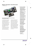
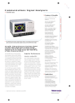
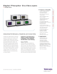
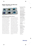
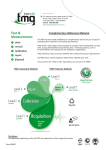
Digital Phosphor Oscilloscopes
TDS5000 Series
Features & Benefits
1 GHz, 500, 350 MHz
Bandwidth Models
2 and 4 Channel Models
5 GS/s Maximum
Real-time Sample Rate
Up to 8 MB Record Length
100,000 wfms/s Maximum
Waveform Capture Rate
Intuitive User Interface
for Easy Operation
OpenChoiceTM with Windows
2000 Delivers Built-in
Networking and Analysis
Small Footprint
10.4 in. (264 mm)
Bright Display
Suite of Advanced Triggers
Built-in Printer (Optional)
CD-RW Drive (Optional)
The TDS5000 Series Digital Phosphor Oscilloscopes
Deliver High-performance Features at an
Unprecedented Price
Interoperability with
Tektronix Logic Analyzers
Applications
Digital Design and Debug
The TDS5000 Series digital phosphor
oscilloscopes (DPO) deliver up to 1 GHz
bandwidth, 5 GS/s real-time sample rate,
8 MB record length and 100,000 wfms/s
maximum waveform capture rate. This performance, along with a suite of advanced
triggers, intuitive user interface, and an open
Windows platform, all in a compact benchtop
package, provides exceptional value.
DPO
Digital phosphor oscilloscopes provide
unmatched insight into signal behavior by
displaying, storing and analyzing complex
signals in real-time using three dimensions
of signal information: amplitude, time and
distribution of amplitude over time. The
TDS5000 DPO Series delivers fast waveform capture rates, enabled by Tektronix
proprietary DPXTM acquisition technology,
saving minutes, hours or even days by
quickly revealing the nature of faults so
sophisticated trigger modes can be applied
to isolate them.
1
Investigation of Transient
Phenomena
Power Measurements
Video Design and Debug
DVD Analysis
Disk Drive Analysis
Jitter and Timing Analysis
Spectral Analysis
Elusive Glitch. Fast waveform capture rate,
enabled by Tektronix proprietary DPX acquisition technology, maximizes the probability
of capturing elusive glitches and other
infrequent events.
Intuitive User Interface
The TDS5000 Series graphical user interface readily adapts to any operating style
and environment, making the oscilloscope
easy to learn and easy to use. Classic analogstyle controls provide instant, front-panel
access to the most frequently used functions
while the large 10.4 in. (264 mm) display
and extensive use of intuitive icons create
a highly visual environment with explicit
illustration of instrument features.
Digital Phosphor Oscilloscopes • www.tektronix.com/tds5000
Automotive Electronics
Design and Debug
Manufacturing Test
and Quality Control
Electro-mechanical
Design and Analysis
Bio-medical Product
Development
Industrial Control
Digital Phosphor Oscilloscopes
TDS5000 Series
Open Windows Platform. TDS5000 Series
waveform display with Excel window and
ActiveX toolbar.
Intuitive User Interface. Whatever your
personal preferences, needs or application
environment, the TDS5000 Series offers
multiple ways to operate the instrument –
classic, analog-style knobs, familiar pulldown menus, mouse, optional touch screen,
and voice commands.
Users can select traditional instrument-style
buttons for navigation or switch to a
Microsoft Windows menu bar. Waveform
positions, cursor locations, and trigger level
can be directly changed using a mouse or
optional touch screen. A graphical drag-box
can be used to select a waveform area for
zooming, histogram analysis or measurement gating. The USB interface allows a
mouse, keyboard, and other peripherals to
be added without powering off the instrument. A context-sensitive help program
supplements graphic control windows and
encourages users to apply advanced capabilities to solve their problems.
OpenChoice Architecture
The TDS5000 Series combines a high performance oscilloscope and a PC in a selfcontained unit. With DPX acquisition technology, OpenChoice Windows desktop, and
application programming interfaces (API)
for Windows and UNIX, this series provides
2
exceptionally fast data acquisition, analysis,
and network accessibility. By using the
embedded PCI bus, waveform data can be
moved directly from acquisition to analysis
applications on the Windows desktop at
much faster speeds than conventional
GPIB transfers.
In the Tektronix TDS5000 DPO Series,
OpenChoice provides a comprehensive software infrastructure for faster, more versatile
operations. Data transfer programs, such as
the Excel Toolbar or Report Generator, are
used to simplify analysis and documentation
on the Windows desktop or on external PCs.
Tektronix’ implementation of industry-standard
protocols, such as TekVISA and ActiveX
Controls, are included for using and enhancing Windows applications for data analysis
and documentation. Or, use the Software
Developer’s Kit (SDK) to help create custom
software to automate multi-step processes
in waveform collection and analysis with
Visual BASIC, C, C++, MATLAB, LabVIEW,
and other common Application Development
Environments (ADE).
Digital Phosphor Oscilloscopes • www.tektronix.com/tds5000
Digital Design and Debug. Tektronix
Integrated View (iView) fully integrates the
performance and measurement accuracy of
a Tektronix oscilloscope with the multichannel and powerful triggering capabilities
of a Tektronix logic analyzer in one display,
allowing designers to quickly verify and
debug their designs.
Integration of the oscilloscope with external
PCs and non-Windows hosts is also supported by the TDS5000 Series software
solutions. Plug-and-play drivers are included to enable easy communication with the
oscilloscope using GPIB, Serial, and LAN
connections from LabVIEW and LabWindows
programs running on external PCs. UNIX
applications, and other LAN resources, can
connect directly using the VXI 11.2 server
included on the TDS5000 Series.
Additional Benefits
The TDS5000 Series includes virtually all
modern standard interfaces for control and
peripheral expansion. An optional built-in
printer provides a snapshot and long banner
print-outs of waveform and measurement
results. An optional CD-RW drive provides
convenient and portable mass storage, making
data transfer much easier for the user who
does not connect the oscilloscope to the
network via the standard LAN connection.
Interoperability of the TDS5000 Series with
Tektronix logic analyzers enables a timecorrelated view of analog and digital signals
to quickly track down elusive signal integrity
problems in designs.
Digital Phosphor Oscilloscopes
TDS5000 Series
Embedded Design. A source synchronous,
double-pumped bus. Channel 1 (yellow)
is the clock signal, Channel 2 (blue) is the
strobe signal, and Channel 3 (pink) is a data
line. The upper half of the graticule shows
a long acquisition of a write-cycle, enabling
designers to gauge the throughput efficiency
of their systems by comparing live writing
time with dead time. The bottom half of the
graticule shows a zoomed-in view of a small
slice of time in the upper graticule, enabling
designers to make critical timing measurements to ensure that the data on the bus
meets the setup-and-hold timing requirements of the receiver.
Applications
The TDS5000 Series’ high performance
features make it ideal for a multitude of
applications, such as digital design and debug,
power measurements, and video design.
Digital Design and Debug
The interoperability of the TDS5000 Series
oscilloscope with the Tektronix logic analyzers
made possible by Tektronix Integrated View
(iViewTM) enables digital designers to solve
signal integrity challenges and effectively
debug and verify their systems more quickly
and easily. The iView feature fully integrates
the industry-leading performance and
measurement accuracy of a Tektronix oscilloscope with the multi-channel and powerful
triggering capabilities of a Tektronix logic
analyzer. This integration allows designers
to view time-correlated digital and analog
data in the same display window and isolate
the analog characteristics of the digital signals
that are causing failures in their systems.
Power Measurements. Channel 1 (yellow,
labeled Voltage) shows the turn-off voltage
on the FET of a switching power supply,
with current on Channel 2 (blue, labeled
Current). The Math 1 waveform, M1 (red,
labeled Power), is the instantaneous power
resulting from the multiplication of the voltage and current waveforms (Ch. 1 * Ch. 2).
The Math 2 waveform, M2 (red, labeled
Energy), is the result of a calculation of the
integral of M1, a math-on-math operation
of the TDS5000 Series. An energy measurement, located to the right of the display,
is a gated measurement made on M1 and
includes statistics. The TDS5000 Series’
powerful and flexible measurement, math,
and math-on-math capabilities make it
an ideal solution for engineers designing
today’s high-efficiency power devices.
The iView Wizard simplifies this integration
of the oscilloscope and logic analyzer by
guiding the user through set up and connection. No user calibration is required. And,
once set up, the iView feature is completely
automated. The result – an integrated tool
set for digital design and troubleshooting.
Embedded Design
With its long record length, high sample rate,
and intuitive zoom model, the TDS5000 Series
simplifies the characterization of today’s
high-speed digital buses, making it an ideal
tool for critical timing measurements in
embedded design applications.
Power Measurements
The TDS5000 Series’ powerful and flexible
measurements, math, and math-on-math
capabilities make it an ideal solution for
making power measurements, such as voltage, current, instantaneous power, and
energy for power device designers.
Display of a current vs. voltage trajectory
XY plot of the DUT. This highly dynamic
waveform display provides continuous
coverage of device performance – the
waveform data is continuously streamed
to the display. Color-grading reveals the
distribution of signal activity for comparison
against device Safe Operating Area (SOA)
characteristics.
Video Design. Illustration of triggering on
an analog HDTV tri-level sync signal and
examining horizontal blanking interval.
Video Design
Tektronix’ exclusive DPX acquisition technology sets the TDS5000 Series apart from
other digital oscilloscopes, enabling the
capture of up to 100,000 waveforms per
seconds for a live, analog-like display. The
TDS5000 Series also supports a wide variety
of video standards with dedicated triggers
including NTSC, PAL, SECAM, and analog
HDTV. In addition, IRE and mV graticules
can be selected for easier measurements
and visual inspection. All of this together
makes the TDS5000 Series an ideal tool
for video design and development.
Digital Phosphor Oscilloscopes • www.tektronix.com/tds5000
3
Digital Phosphor Oscilloscopes
TDS5000 Series
Trigger Modes
Edge – Positive or negative slope on any channel
or front panel auxiliary input. Coupling includes DC,
AC, noise reject, HF reject, and LF reject.
Characteristics
VERTICAL SYSTEM
TDS5032/
TDS5034
TDS5052/
TDS5054
TDS5104
Video – Trigger on NTSC, PAL, SECAM, analog
HDTV, and non-standard video formats.
2/4
2/4
4
Analog Bandwidth (–3 dB)
5 mV/div to 1 V/div
350 MHz
500 MHz
1 GHz
Glitch – Trigger on or reject glitches of positive,
negative or either polarity. Minimum glitch width
is 1.0 ns with 200 ps resolution.
Calculated Rise Time
5 mV/div (typical)
1.15 ns
800 ps
300 ps
Input Channels
Hardware Bandwidth Limits
150 MHz or 20 MHz
Input Coupling
Runt – Trigger on a pulse that crosses one threshold but fails to cross a second threshold before
crossing the first again. Event can be time or logic
qualified (logic on 4 channel models only).
AC, DC, GND
Input Impedance
1 MΩ ±1% or 50 Ω ±1%
Input Sensitivity, 1 MΩ
1 mV/div to 10 V/div
Input Sensitivity, 50 Ω
1 mV/div to 1 V/div
Vertical Resolution
8-bits (>11-bits with averaging)
Max Input Voltage, 1 MΩ
±150 V CAT I derate at 20 dB/decade to 9 VRMS above 200 kHz
Max Input Voltage, 50 Ω
5 VRMS with peaks <±30 V
DC Gain Accuracy
1.5% with offset set to 0 V
Offset Range, 1 MΩ
Offset Range, 50 Ω
Channel-to-channel Isolation
Any Two Channels at Equal
Vertical Scale
Window – Trigger on an event that enters or exits
a window defined by two user-adjustable thresholds. Event can be time or logic qualified (logic on
4 channel models only).
Timeout – Trigger on an event which remains
high, low or either, for a specified time period,
selectable from 1 ns to 1 s with 200 ps resolution.
1 mV/div to 99.5 mV/div ±1 V
100 mV/div to 1 V/div ±10 V
1.01 V/div to 10 V/div ±100 V
1 mV/div to 99.5 mV/div ±1 V
100 mV/div to 1 V/div ±10 V
Width – Trigger on width of positive or negative
pulse either within or out of selectable time limits
ranging from 1 ns to 1 s with 200 ps resolution.
Transition – Trigger on pulse edge rates that are
faster or slower than specified. Slope may be
positive, negative or either.
1 mV to 50 mV/div
±0.5 V
50.5 mV to 99.5 mV
±0.25 V
100 mV to 500 mV
±5 V
505 mV to 1 V/div
±2.5 V
≥100:1 at ≤100 MHz and ≥30:1
at >100 MHz up to the rated bandwidth
Setup/Hold – Trigger on violations of both setup
time and hold time between clock and data present
on any two input channels.
Pattern – Trigger when pattern goes false or stays
true for specified period of time. Pattern (AND, OR,
NAND, NOR) specified for four input channels
defined as High, Low or Don’t Care.
State – Any logical pattern of channels (1, 2, 3)
clocked by edge on channel 4 (channel 2 on
TDS5052). Trigger on rising or falling clock edge.
Trigger Delay by Time – 16 ns to 250 seconds.
TIMEBASE SYSTEM
Trigger Delay by Events – 1 to 10,000,000 Events.
All Models
Timebase Range
200 ps/div to 40 s/div
Timebase Delay Time Range
16 ns to 250 s
Channel-to-channel Deskew Range
±75 ns
Delta Time Measurement Accuracy
±(0.30 sample interval) + (15 ppm * reading)
Trigger Jitter (RMS)
Long Term Sample Rate and Delay Time Accuracy
Waveform Measurements
Amplitude – Amplitude, High, Low, Maximum,
Minimum, Peak to Peak, Mean, Cycle Mean, RMS,
Cycle RMS, Positive Overshoot, Negative Overshoot.
8 psRMS (typical)
Time – Rise Time, Fall Time, Positive Width,
Negative Width, Positive Duty Cycle, Negative Duty
Cycle, Period, Frequency, Delay.
±15 ppm over ≥1 ms interval
Combination – Area, Cycle Area, Phase, Burst Width.
Histogram-related (optional) – Waveform count,
Hits in box, Peak hits, Median, Maximum,
Minimum, Peak to Peak, Mean (µs), Standard
Deviation (sigma), µ+1 (σ), µ+2 (σ), µ+3 (σ).
4
Digital Phosphor Oscilloscopes • www.tektronix.com/tds5000
Digital Phosphor Oscilloscopes
TDS5000 Series
Waveform Processing/Math
Characteristics, cont.
Standard Math
Arithmetic – Add, subtract, multiply, and
divide waveforms.
ACQUISITION SYSTEM
2 Ch Models
(TDS5032/5052)
Real-time Sample Rates
1 Channel (max)
2 Channels (max)
3-4 Channels (max)
Equivalent Time Sample
Rate (max)
Maximum Record Length
per Channel with
Standard Memory
With Opt. 1M
With Opt. 2M
4 Ch Models
(TDS5034/5054/5104)
Window Functions – Rectangular, Hamming,
Hanning, Kaiser-Bessel, Blackman-Harris,
Gaussian, Flattop2, Tek Exponential.
—
1.25 GS/s
400 k (1 ch), 200 k (2 ch)
400 k (1 ch), 200 k (2 ch),
100 k (4 ch)
2 M (1 ch), 1 M (2 ch)
8 M (1 ch), 4 M (2 ch)
2 M (1 ch), 1 M (2 ch), 500 k (4 ch)
8 M (1 ch), 4 M (2 ch), 2 M (4 ch)
All Models
200 ps (5 GS/s)
80 µs
400 µs
1.6 ms
All Models
FastAcq optimizes the instrument for analysis of dynamic signals
and capture of infrequent events
100,000 wfms/s
From 2 to 10,000 waveforms included in average
From 2 to 2 x 10⁹ waveforms included in min-max envelope
Real-time boxcar averaging reduces random noise
and increases resolution
Acquisition memory divided into segments;
maximum trigger rate >225,000 waveforms per second
All Models
Trigger Level Range
Internal
External (auxiliary in)
Line
Trigger Coupling
Trigger Holdoff Range
Frequency Domain Functions – Spectral magnitude and phase, real and imaginary spectra.
Additional Vertical Units – Phase: degrees, radians.
Display Characteristics
Display Type – Liquid crystal active-matrix color
display.
Display Size – 211.2 mm (W) x 158.4 mm (H),
264 mm (10.4 in) diagonal.
Waveform Styles – Vectors, Dots, Intensified
Samples, Variable Persistence, Infinite Persistence.
Computer System
and Peripherals
CPU – Intel Celeron Processor, 1.2 GHz.
Acquire sampled values
Captures narrow glitches at all real-time sampling rates
<1 ns
TRIGGER SYSTEM
Sensitivity
Internal DC Coupled
External (auxiliary input)
Main Trigger Modes
Trigger Sequences
Calculus – Integrate, differentiate.
Display Resolution – 640 horizontal x 480 vertical
pixels.
ACQUISITION MODES
FastFrameTM Acquisition
Optional Math
Algebraic Expressions – Define extensive algebraic
expressions including waveforms, scalars, and
results of parametric measurements e.g. (Integral
(Ch1-Mean(Ch1))*1.414).
250 GS/s
Time Resolution (single shot)
Max Duration with Standard Memory
Max Duration with Opt. 1M
Max Duration with Opt. 2M
Maximum FastAcq Waveform
Capture Rate
Sample
Peak Detect
Minimum Peak Detect
Pulse Width
Averaging
Envelope
Hi-Res
Vertical Units – Magnitude: Linear, dB, dBm.
5 GS/s
2.5 GS/s
MAXIMUM DURATION AT HIGHEST REAL-TIME RESOLUTION (1 ch)
FastAcq Acquisition
FFT – Magnitude.
PC System Memory – 256 MB.
Hard Disk Drive – ≥20 GB capacity.
Floppy Disk Drive – Front panel 3.5 in floppy disk
drive, 1.44 MB capacity.
CD-ROM Drive – Side panel CD-ROM drive.
CD-RW Drive (Optional) – Side panel CD-RW
drive.
Printer (Optional) – Built-in thermal printer.
Mouse – Logitech thumb wheel model included,
USB interface.
Keyboard – Order 119-6633-00 (USB interface).
0.35 div DC to 50 MHz increasing to 1 div at 500 MHz
400 mV from DC to 50 MHz increasing to 750 mV at 100 MHz
Auto, Normal, and Single
Main, Delayed by time, Delayed by events. All sequences can include
separate horizontal delay after the trigger event to position
the acquisition window in time
±10 divisions from center of screen
±8 V
Fixed at 0 V
DC, AC (attenuate <60 Hz), HF reject (attenuate >30 kHz),
LF reject (attenuates <80 kHz, noise reject (reduce sensitivity)
250 ns minimum to 12 s maximum
Digital Phosphor Oscilloscopes • www.tektronix.com/tds5000
5
Digital Phosphor Oscilloscopes
TDS5000 Series
OpenChoice Software
Input/Output Ports
Physical Characteristics
TekVISA – Application Programmers Interface (API)
for Windows developers. Documentation includes
descriptions and samples of programming test and
measurement applications on the unit in Visual
BASIC, C and C++.
Auxiliary Input – Front panel BNC connector.
Trigger level range is adjustable from +8 V to –8 V.
The maximum input voltage is ±20 V.
BENCHTOP CONFIGURATION
Dimensions
mm
Height
285
Width
447
Depth
288
Weight
kg
Net
10.55
Shipping
25
in.
11.2
17.6
11.35
lbs.
23.25
55
RACKMOUNT CONFIGURATION
Dimensions
mm
Height
267
Width
483
Depth
288
Weight
kg
Net
11.8
Kit
5
in.
10.5
19
11.35
lbs.
26
11
TekVisa Control (TVC) – Active controls to make
access to TekVISA easy for integration into
Microsoft Windows applications.
VXI-11 server – An Application Programmers
Interface (API) for LAN connectivity from nonWindows environments.
For information regarding TDS5000 Series
compatibility with National Instruments hardware
and software products, contact your local Tektronix
account manager.
For information about using a TDS5000 Series
oscilloscope as a GPIB controller, contact your
local Tektronix account manager.
Probe Compensator Output – Front panel pins.
Amplitude 1 V ± 1% into a ≥10 kΩ load, frequency
1 kHz ±5%.
Analog Signal Output Amplitude – Rear-panel
BNC connector, provides a buffered version of the
signal that is attached to the Channel 3 input. 20
mV/div ±20% into a 1 MΩ load, 10 mV/div ±20%
into a 50 Ω load (4 channel models only).
Analog Signal Output Bandwidth, Typical –
100 MHz into a 50 Ω load (4 channel models only).
Auxiliary Output Levels – Rear-panel BNC connector, provides a TTL-compatible, negative polarity
pulse when the oscilloscope triggers.
External Reference In – Rear-panel BNC connector.
9.8 MHz to 10.2 MHz.
Plug-and-play Drivers – Provides support to run
National Instrument’s LabVIEW and LabWindows
on an external PC connected to a TDS5000 Series
oscilloscope.
Parallel Port – IEEE 1284, DB-25 connector.
IVI Drivers – Provides support for new and existing
program environments utilizing the IVI instrumentation standard, such as LabVIEW, LabWindows/CVI,
MATLAB, Visual BASIC, and C/C++.
USB Port – Allows connection or disconnection
of USB keyboard and/or mouse while oscilloscope
power is on.
Excel Toolbar – Provides direct access to waveforms and measurements on the oscilloscope from
a toolbar in Excel.
Mouse Port – PS-2 compatible.
Report Generator – Enables the ability to design
and create customized report templates that
extract the oscilloscope’s waveforms, settings,
measurements, and other on-screen information
with a click of the mouse.
LabVIEW and MATLAB – 30 day evaluation copies
plus non-expiring demo programs that perform a
variety of LabVIEW and MATLAB display and analysis functions with the oscilloscope.
Software Developer’s Kit (SDK) – A CD is included
in the Getting Started With OpenChoice TM book.
This SDK includes a wealth of documentation,
programming tools, and examples to assist programmers working with the TDS5000 Series.
Audio Ports – Miniature phone jacks for stereo
microphone input and stereo line output.
Keyboard Port – PS-2 compatible.
LAN Port – RJ-45 connector, supports 10Base-T
and 100Base-T.
Serial Port – DB-9 COM1 port.
SVGA Video Port – DB-15 female connector;
connect a second monitor to use dual-monitor
display mode. Supports basic requirements of
PC99 specifications.
GPIB Port – IEEE 488.2 standard.
Scope VGA Video Port – DB-15 female connector,
31.6 kHz sync, EIA RS-343A compliant, connect to
show the oscilloscope display, including live waveforms on an external monitor or projector.
Power Source
Power – 100 to 240 VRMS ±10%, 47 to 63 Hz;
CAT II, <220 W.
MECHANICAL
Cooling – Required Clearance for Benchtop
Configuration
Dimensions
mm
Top
0
Bottom
0
Left Side
76
Right Side
0
Front
0
Rear
0
in.
0
0
3
0
0
0
Environmental
Temperature
Operating – +5 ºC to +45 ºC.
Nonoperating – –20 ºC to +60 ºC without diskette
in floppy drive.
Humidity
Operating – 20% to 80% relative humidity with a
maximum wet bulb temperature of +29 ºC at or
below +50 ºC, noncondensing. Upper limit derated
to 25% relative humidity at +50 ºC.
Nonoperating – With no diskette in floppy disk
drive. 5% to 90% relative humidity with a maximum wet bulb temperature of +29 ºC at or below
+60 ºC, noncondensing. Upper limit derated to
20% relative humidity at +60 ºC.
Altitude
Operating – 10,000 ft. (3,048 m).
Nonoperating – 40,000 ft. (12,190 m).
Random Vibration
Operating – 0.1 GRMS from 5 to 500 Hz, 10 minutes
each axis, 3-axes, 30 minutes total.
Nonoperating – 2.0 GRMS from 5 to 500 Hz, 10
minutes each axis, 3-axes, 30 minutes total.
Electromagnetic Compatibility – 89/336/EEC.
Safety – UL 3111-1, CSA-22.2 No. 1010.1,
EN61010-1, IEC61010-1/A2.
6
Digital Phosphor Oscilloscopes • www.tektronix.com/tds5000
Digital Phosphor Oscilloscopes
TDS5000 Series
I n s t r u m e n t O p t i o n s ( Av a i l a b l e w h e r e i n d i c a t e d b y ‘ x ’ )
TDS5032
TDS5034
TDS5052
TDS5054
TDS5104
Hardware Options
16
CD-RW drive
x
x
x
x
x
17
Additional 256 MB of RAM
x
x
x
x
x
18
Touch-screen interface
x
x
x
x
x
1P
Built-in thermal printer
x
x
x
x
x
Acquisition Memory Options
1M
2 Msamples max (1 ch)
x
x
x
x
x
2M
8 Msamples max (1 ch)
x
x
x
x
x
1K
K420 oscilloscope cart
x
x
x
x
x
1R
Rackmount kit
x
x
x
x
x
2A
Advanced analysis – equation editor, spectral FFT,
and histograms
x
x
x
x
x
J2
TDSDDM2 – Disk drive measurements software
x
x
x
JT3
TDSJIT3 – Jitter and timing analysis software
x
x
x
J3E
TDSJIT3E – Jitter and timing analysis
software essentials
x
x
x
Mounting Options
Software Options
DVD
DVD – Optical storage analysis software
x
x
x
x
x
PW2
TDSPWR2 – Power measurements software
x
x
x
x
x
USB
TDSUSBS – USB2.0 compliance test software only
x
x
x
x
Bundle Options
TSY
Includes options 16, 17, 18, 1P, 2A, and 2M
x
x
x
x
Probe Options
33
Add (1) P6158 3.0 GHz, 20x low C probe
34
Add (1) P6247 1.0 GHz differential probe
x
x
x
x
x
35
Add (1) P6243 1.0 GHz active probe
x
x
x
x
37
Add (1) P6245 1.5 GHz active probe
x
39
Add (1) P6248 1.7 GHz differential probe
x
53
Add (1) P5050 500 MHz, 10x passive probe
x
x
x
x
x
Manual Options
L0
English User Manual
x
x
x
x
x
L5
Japanese User Manual
x
x
x
x
x
L10
Russian User Manual
x
x
x
x
x
Opt. C3
Calibration Service 3 Years
x
x
x
x
x
Opt. C5
Calibration Service 5 Years
x
x
x
x
x
Opt. D1
Calibration Data Report
x
x
x
x
x
Opt. D3
Calibration Data Report 3 Years (with Option C3)
x
x
x
x
x
Opt. D5
Calibration Data Report 5 Years (with Option C5)
x
x
x
x
x
Opt. R3
Repair Service 3 Years
x
x
x
x
x
Service
Digital Phosphor Oscilloscopes • www.tektronix.com/tds5000
7
Digital Phosphor Oscilloscopes
Contact Tektronix:
TDS5000 Series
ASEAN / Australasia / Pakistan (65) 6356 3900
Austria +43 2236 8092 262
Belgium +32 (2) 715 89 70
Brazil & South America 55 (11) 3741-8360
Ordering Information
TDS5032 – 350 MHz, 2 channel digital phosphor
oscilloscope.
TDS5034 – 350 MHz, 4 channel digital phosphor
oscilloscope.
TDS5052 – 500 MHz, 2 channel digital phosphor
oscilloscope.
TDS5054 – 500 MHz, 4 channel digital phosphor
oscilloscope.
TDS5104 – 1 GHz, 4 channel digital phosphor
oscilloscope.
All Models Include: Front Cover (200-4651-00),
Mouse (119-6298-00), Quick Reference
(020-2398-00), GPIB Programmer’s Reference,
TDS5000 Series Product Software CD-ROM,
TDS5000 Series Operating System Restoration
CD-ROM, Getting Started with OpenChoice TM book,
and Software Developer’s Kit CD (020-2513-00),
Performance Verification Procedure PDF file,
Calibration Certificate Documenting NIST
Traceability, Z540-1 Compliance, and ISO9001
Registration, Power Cord.
Please specify power plug and manual version
when ordering.
TDS5032/TDS5052 Also Includes – (2) P5050
500 MHz, 10x passive probes.
TDS5034 / TDS5054 Also Includes – (4) P5050
500 MHz, 10x passive probes.
TDS5104 – No probes included.
Power Plug Options
Opt. A0 – US Plug, 115 V, 60 Hz.
Opt. A1 – Euro Plug, 220 V, 50 Hz.
Opt. A2 – UK Plug, 240 V, 50 Hz.
Opt. A3 – Australian Plug, 240 V, 50 Hz.
Opt. A5 – Swiss Plug, 220 V, 50 Hz.
Opt. AC – China Plug, 50 Hz.
Opt. A99 – No Power Cord.
Recommended Accessories
Keyboard (USB interface) – Order 119-6633-00.
Service Manual – Order 071-1004-xx.
Transit Case – Order 016-1937-00.
Scope Cart – Order K420 and 436-0317-00
(mouse accessory tray).
Video Display Clamp – Order 013-0278-xx.
Thermal Printer Paper – Order 016-1897-00.
8
Instrument Upgrades
Canada 1 (800) 661-5625
Upgrades equivalent to original options can be
ordered to extend instrument performance after
initial purchase. Users can install most upgrades
without opening the instrument case or requiring
on-site service (except for Options 16, 18, MU,
and CPU). Order a TDS5UP and the appropriate
option(s) listed below.
Central Europe & Greece +43 2236 8092 301
Denmark +45 44 850 700
Finland +358 (9) 4783 400
France & North Africa +33 (0) 1 69 86 80 34
Germany +49 (221) 94 77 400
TDS5UP Upgrade Kit (Kit
requires at least one option)
Opt. 16 – Upgrade from CD-ROM to CD-RW.
Opt. 18 – Upgrade to touch screen.
Opt. 1P – Upgrade to integrated thermal printer.
Opt. M01 – Upgrade memory depth from standard
to Opt. 1M.
Opt. M02 – Upgrade memory depth from standard
to Opt. 2M.
Opt. M12 – Upgrade memory depth from Opt. 1M
to Opt. 2M.
Opt. MU – Add 256 MB of PC RAM.
Opt. 2A – Advanced analysis: equation editor,
spectral FFT, and histograms.
Opt. JT3 – TDSJIT3: Jitter and timing analysis
software with Rj/Dj and BER.
Opt. J3E – TDSJIT3E: Jitter and timing analysis
software essentials.
Opt. J23 – Upgrade TDSJIT2 jitter and timing
analysis software to TDSJIT3.
Opt. J2E – Upgrade TDSJIT2 jitter and timing
analysis software to TDSJIT3E.
Opt. J2 – TDSDDM2: Disk drive measurements
software.
Opt. DVD – TDSDVD: Optical storage analysis
software.
Opt. PW2 – TDSPWR2: Power measurements
software.
Opt. USB – USB 2.0 Compliance test
software.
Opt. CPU – Upgrade motherboard and processor.
Opt. W2K – Upgrade from Windows Me to
Windows 2000.
Opt. IF – Factory installation of selected options.
Digital Phosphor Oscilloscopes • www.tektronix.com/tds5000
Hong Kong (852) 2585-6688
India (91) 80-2275577
Italy +39 (02) 25086 1
Japan 81 (3) 3448-3010
Mexico, Central America & Caribbean 52 (55) 56666-333
The Netherlands +31 (0) 23 569 5555
Norway +47 22 07 07 00
People’s Republic of China 86 (10) 6235 1230
Poland +48 (0) 22 521 53 40
Republic of Korea 82 (2) 528-5299
Russia, CIS & The Baltics +358 (9) 4783 400
South Africa +27 11 254 8360
Spain +34 (91) 372 6055
Sweden +46 8 477 6503/4
Taiwan 886 (2) 2722-9622
United Kingdom & Eire +44 (0) 1344 392400
USA 1 (800) 426-2200
USA (Export Sales) 1 (503) 627-1916
For other areas contact Tektronix, Inc. at: 1 (503) 627-7111
Updated 20 September 2002
Our most up-to-date product information is available at:
www.tektronix.com
Product(s) are manufactured
in ISO registered facilities.
Copyright © 2003, Tektronix, Inc. All rights reserved. Tektronix products are covered
by U.S. and foreign patents, issued and pending. Information in this publication
supersedes that in all previously published material. Specification and price change
privileges reserved. TEKTRONIX and TEK are registered trademarks of Tektronix,
Inc. All other trade names referenced are the service marks, trademarks or registered trademarks of their respective companies.
06/03
HB/SFI
55W-14869-4