1
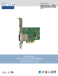
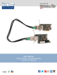
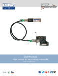
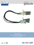
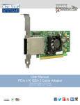
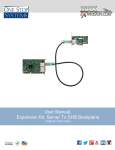
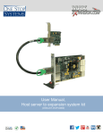
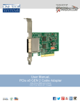
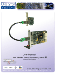
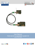
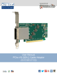
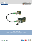
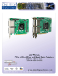
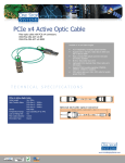
User Manual PCIe x4 Gen2 Switch-based Cable Adapter OSS-PCIe-HIB35-x4 Table of Contents 1. Overview 1.a. Board Description ................................................................................................................................ 3 1.a.1 Network Adapter................................................................................................................................ 3 1.a.2 I/O adapter ........................................................................................................................................ 3 2. Components 2.a. Host interface board ............................................................................................................................ 4 2.b. Block diagram...................................................................................................................................... 4 2.c. Cable adapter specifications ............................................................................................................... 5 2.d. LED description ................................................................................................................................... 6 2.e. Switch description ............................................................................................................................... 7 3. Installation Instructions 3.a. Connecting the PCIe cable .................................................................................................................. 8 3.b. Removing the PCIe cable .................................................................................................................... 8 4. Technical Information 4.a. Dip switch configurations ..................................................................................................................... 9 4.b. Appendix A .......................................................................................................................................... 10 4.c. Signal Descriptions .............................................................................................................................. 10 4. Ordering Information One Stop Systems Specifications subject to change without notice OSS-PCIe-HIB35-x4 Page 2 1. Overview 1.a. Board Description The switch-based is PCIe x4 cable adapter can be used in two modes; as a network adapter between two systems and as an I/O adapter between a host system and a downstream I/O device. 1.a.1 Network adapter The switch-based cable adapter can be configured to operate in upstream and downstream modes when cabled between two processors. The main function of the switch-based board is to: 1) isolate the spread spectrum clock that is transmitted from both processors, and 2) allow memory transfers from one processor’s memory to the other’s memory When used in this architecture, it is assumed that the customer is writing a specific driver for his application or using the ExpressNet 2.0 driver installed on both systems. 1.a.2 I/O adapter The switch-based adapter can also be used in a host system cabled to a downstream I/O device in applications where noise from the host system must be isolated from the downstream appliance by the switch. Note: See the factory for the availability of the ExpresssNet 2.0 driver. Note: The clock on the switch-based adapter is set at 100.3 Mhz due to a PCIe specification requirement that states that in order to isolate spread spectrum, the clock between the two systems must be set to higher than the anticipated jitter of the 100mhz clock. Therefore, if the application is to operate the HIB35x4 from a host system to a downstream device that emits its own clock, a downstream HIB35x4 must also be used. One Stop Systems Specifications subject to change without notice OSS-PCIe-HIB35-x4 Page 3 2. Components 2.a. Host Interface Board The PCIe x4 Gen 2 host cable adapter that allows PC to PC communication when used with another HIB-35 and the ExpressNet driver. It includes PCIe 8-lane switch including NT port (non-transparent) and built-in DMA controller. Full height or half height bracket Link LEDs PCIe x4 cable connector PCIe x4 edge connector 2.b. Block diagram PLX Technology PEX8609 PCIe Switch Gen 2 8 Lane x4 PCIe Cable Connector POWER REGULATION EEPROM 100MHz Clock Generator PCIe x4 Card Edge Connector One Stop Systems Specifications subject to change without notice OSS-PCIe-HIB35-x4 Page 4 2.c. Cable adapter specifications Form Factor PCIe low profile Operating Temperature 0˚C to +50˚C environment Storage Temperature -40˚C to 85˚C Operating Humidity 10% to 90% relative humidity non-condensing Storage Humidity 5% to 95% relative humidity non-condensing Power 0.4A @ 12V Connectors • PCIe x4 cable connector • PCIe x4 edge connector Industry Specifications • PCIe External Cabling Specification, Rev. 1.0 • PCI Express™ Card Electromechanical Specification, Rev. 2.0 • PCI Express ® Base Specification, Rev. 2.0 PCB • PCI Express add-in card standard • x4 PCIe cable to front panel PCIe Switch • 5.0 Gbps 4-Lane PCI Express Gen 2 Bracket • Standard and low profile brackets available • Cable connection LED Agency Compliance Pending: • FCC Class B • CE One Stop Systems Specifications subject to change without notice OSS-PCIe-HIB35-x4 Page 5 2.d. LED Description The LEDs on the slot cover show lanes that have successfully linked. Lanes 1-4 are represented by LEDs 0-3 Solid LEDs show a good link OFF = no link Flashing LEDs = train unsuccessful There are 2 sets of 4 LEDs on the back of the HIB35-x4. They are located in the upper right hand corner of the board. The first set is labeled as followed: PWR--Power good RST—Card edge Reset CRST—Cable Reset FE—PEX Fatal Error Power LED should always be solid when the card is active. RST and CRST will flash when reset occurs. FE will be lit only when the PCIe switch has detected a fatal error. The second set of 4 LEDs show the PCIe lane width connection through the card edge to host system. LEDs 0-3 represent lanes 1-4. These LEDs will be solid when a link is established and off when there is no link. If an LED is flashing, the link is training unsuccessfully. CRST—Cable Reset RST—Card edge reset FE—PEX Fatal Error Card edge connection Power on One Stop Systems Specifications subject to change without notice OSS-PCIe-HIB35-x4 Page 6 2.e. Switch Description 8 Lane, 8 Port PCI Express Switch, 15 x 15mm PBGA The ExpressLane™ PEX 8609 offers 8 PCI Express Gen 2 (5.0 GT/s) lanes, capable of configuring up to 8 flexible ports and fully conforms to the PCI Express Base Specification, rev 2.0. PEX 8609 architecture supports a high-performance DMA engine with four DMA channels and internal buffer space for internal descriptor support. Up to 256 descriptors are supported internally or alternatively descriptors can also exist in host memory. Each descriptor provides support for large transfer sizes (up to 128MB) giving the user the capability to perform very large data transfers in any direction (memory to device, device to device, memory to memory). PEX 8609 also supports cut-thru with the industry's lowest latency of 140ns (x4 to x1) and offers two virtual channels for traffic prioritization in the system. The device also features an on-chip Non-Transparent port for dualhost and failover applications and supports dual-clock domain operation by virtue of support for Spread Spectrum Clock (SSC) isolation, is offered in a 15 x 15mm 324-ball PBGA and is available in both leaded and lead-free packaging. This device supports Access Control Services (ACS). One Stop Systems Specifications subject to change without notice OSS-PCIe-HIB35-x4 Page 7 3. Installation Instructions 3.a. Connecting the PCIe cable 1) Firmly insert the cable connector into the board cable connector shell. The teeth on the cable connector shell MUST engage completely in the holes on the board connector shell. Always check the connection if link problems are exhibited. 3.b. Removing the PCIe cable: 1) Pull back on the green thumb tab to release the metal teeth and pull the cable connector out of the board connector shell. One Stop Systems Specifications subject to change without notice OSS-PCIe-HIB35-x4 Page 8 4. Technical Information 4.a. Dip switch configurations The following dip switch configurations are required for proper board operation in network and I/O architectures. To operate the boards in a network scheme, the dip switches of the two boards must be set in option A (Host) and option B (Target) configurations. To operate the boards in an I/O scheme, the dip switches must be set in option A (Host) and option C (Target) configurations. The following diagrams show the dip switch settings more visibly: NOTE: Option D is a factory setting and is not for user configuration One Stop Systems Specifications subject to change without notice OSS-PCIe-HIB35-x4 Page 9 4.b. Appendix A Pin out for PCIe x4 cable connector Pin # A1 A4 A7 A10 A13 A16 B1 B4 B7 B10 B13 A2 A3 A5 A6 Cable Side 1 GND Pin # A8 A9 A11 A12 A14 A15 A17 A18 A19 B2 B3 B5 B6 B8 B9 B11 B12 B14 B15 B16 B17 B18 B19 Cable Side 1 PETp2 PETn2 PETp3 PETn3 CREFCLK+ CREFCLK SB_RTN CPRSNT# CPWRON PERp0 PERn0 PERp1 PERn1 PERp2 PERn2 PERp3 PERn3 PWR PWR PWR_RTN PWR_RTN CWAKE# CPERST# Backshell Chassis Ground PETp0 PETn0 PETp1 PETn1 Drain Wires Differential Pair Differential Pair Differential Pair Differential Pair Differential Pair Hook-up Wire Hook-up Wire Hook-up Wire Differential Pair Differential Pair Differential Pair Differential Pair NC NC NC NC Hook-up Wire Hook-up Wire Overall Cable Braid Cable Side 2 GND PERp0 PERn0 PERp1 PERn1 Pin # A1 A4 A7 A10 A13 A16 B1 B4 B7 B10 B13 B2 B3 B5 B6 Cable Side 2 PERp2 PERn2 PERp3 PERn3 CREFCLK+ CREFCLKSB_RTN CPRSNT# CPWRON PETp0 PETn0 PETp1 PETn1 PETp2 PETn2 PETp3 PETn3 PWR PWR PWR_RTN PWR_RTN CWAKE# CPERST# Pin # B8 B9 B11 B12 A14 A15 A17 A18 A19 A2 A3 A5 A6 A8 A9 A11 A12 B14 B15 B16 B17 B18 B19 Chassis Ground Backshell 4.c. Signal Descriptions PETp(x) PCI Express Transmit Positive signal of (x) pair. PETn(x) PCI Express Transmit Negative signal of (x) pair. PERp(x) PCI Express Receive Positive signal of (x) pair. PERn(x) PCI Express Receive Negative signal of (x) pair. Cable REFerence CLocK: Provides a reference clock from the host system to the remote system. Side Band ReTurN: return path for single ended signals from remote systems. CREFCLK+/SB_RTN CPRSNT# PWR_RTN Cable PReSeNT: Indicates the presence of a device beyond the cable. PoWeR: Provides local power for in-cable redriver circuits. Only needed on long cables. Power does not go across the cable.) PoWeR ReTurN: Provides local power return path for PWR pins. CWAKE# Cable WAKE CPERST# Cable PCI Express Reset PWR One Stop Systems Specifications subject to change without notice OSS-PCIe-HIB35-x4 Page 10 5. Ordering Information OSS-PCIe-HIB35-x4 - PCIe Gen 2 Host Interface Board (HIB) with the full height bracket OSS-PCIe-HIB35-x4 - Half height bracket Related Products OSS-PCIe-HIB25-x4-H - PCIe x4 Gen 2 host cable adapter installs in a x4, x8, or x16 expansion slot of a host system to extend the host PCIe bus to an expansion system or PCIe devise. OSS-PCIe-HIB25-x4-T - PCIe x4 GEN 2 target cable adapter is only used with the OSS 2-slot PCIe backplane to add a single PCIe card to a host. OSS-SHB-ELB-x4/x8-2.0 - PCIe x8 or x4 Gen 2 expansion link board installs in SHBe slot of a PCIe Gen 2 back plane, allowing either x8 or x4 cable inputs from upstream host system. OSS-PCIe-CBL-x4-2M - 2 meter PCIe x4 cable with PCIe x4 connectors. One Stop Systems OSS-KIT-EXP-8000-2M 9