1
User’s
Manual
Model DM8
Vibration Type Density Meter
IM 12T03A01-02E
R
IM 12T03A01-02E
4th Edition
i
uIntroduction
This manual describes the specifications, installation, operation, maintenance, and
troubleshooting for the Model DM8 Vibration Type Density Meter. To use this manual
correctly, read this manual thoroughly.
This manual is applied to the following product.
Detector:
VD6D (Style B), VD6DF (Style B), VD6DS (Style B)
Converter:
DM8C (Style C)
Special Cable: DM8W (Style A)
For the Model VD6SM Sampling System, refer to IM 12T3S1-01E.
n Notes on Handling User’s Manuals
• Please hand over the user’s manuals to your end users so that they can keep the user’s
manuals on hand for convenient reference.
• Please read the information thoroughly before using the product.
• The purpose of these user’s manuals is not to warrant that the product is well suited to any
particular purpose but rather to describe the functional details of the product.
• No part of the user’s manuals may be transferred or reproduced without prior written
consent from YOKOGAWA.
• YOKOGAWA reserves the right to make improvements in the user’s manuals and product at
any time, without notice or obligation.
• If you have any questions, or you find mistakes or omissions in the user’s manuals, please
contact our sales representative or your local distributor.
Media No. IM 12T03A01-02E
4th Edition : Feb. 2015 (YK)
All Rights Reserved Copyright © 2006, Yokogawa Electric Corporation
IM 12T03A01-02E
4th Edition : Feb. 23, 2015-00
ii
u
Safety Precautions
n Safety, Protection, and Modification of the Product
• In order to protect the system controlled by the product and the product itself and ensure
safe operation, observe the safety precautions described in this user’s manual. We assume
no liability for safety if users fail to observe these instructions when operating the product.
• If this instrument is used in a manner not specified in this user’s manual, the protection
provided by this instrument may be impaired.
• If any protection or safety circuit is required for the system controlled by the product or for
the product itself, prepare it separately.
• Be sure to use the spare parts approved by Yokogawa Electric Corporation (hereafter
simply referred to as YOKOGAWA) when replacing parts or consumables.
• Modification of the product is strictly prohibited.
• The following safety symbols are used on the product as well as in this manual.
WARNING
This symbol indicates that an operator must follow the instructions laid out in this manual in order
to avoid the risks, for the human body, of injury, electric shock, or fatalities. The manual describes
what special care the operator must take to avoid such risks.
CAUTION
This symbol indicates that the operator must refer to the instructions in this manual in order to
prevent the instrument (hardware) or software from being damaged, or a system failure from
occurring.
CAUTION
This symbol gives information essential for understanding the operations and functions.
NOTE
This symbol indicates information that complements the present topic.
n Warning and Disclaimer
The product is provided on an “as is” basis. YOKOGAWA shall have neither liability nor
responsibility to any person or entity with respect to any direct or indirect loss or damage arising
from using the product or any defect of the product that YOKOGAWA can not predict in advance.
IM 12T03A01-02E
4th Edition : Feb. 23, 2015-00
iii
u
After-sales Warranty
n Do not modify the product.
n During the warranty period, for repair under warranty consult the local sales
representative or service office. Yokogawa will replace or repair any damaged
parts. Before consulting for repair under warranty, provide us with the model
name and serial number and a description of the problem. Any diagrams or
data explaining the problem would also be appreciated.
• If we replace the product with a new one, we won’t provide you with a repair report.
• Yokogawa warrants the product for the period stated in the pre-purchase quotation
Yokogawa shall conduct defined warranty service based on its standard. When the
customer site is located outside of the service area, a fee for dispatching the maintenance
engineer will be charged to the customer.
n In the following cases, customer will be charged repair fee regardless of
warranty period.
• Failure of components which are out of scope of warranty stated in instruction manual.
• Failure caused by usage of software, hardware or auxiliary equipment, which Yokogawa
Electric did not supply.
• Failure due to improper or insufficient maintenance by user.
• Failure due to modification, misuse or outside-of-specifications operation which Yokogawa
does not authorize.
• Failure due to power supply (voltage, frequency) being outside specifications or abnormal.
• Failure caused by any usage out of scope of recommended usage.
• Any damage from fire, earthquake, storms and floods, lightning, disturbances, riots, warfare,
radiation and other natural changes.
n Yokogawa does not warrant conformance with the specific application at the
user site. Yokogawa will not bear direct/indirect responsibility for damage due
to a specific application.
n Yokogawa Electric will not bear responsibility when the user configures the
product into systems or resells the product.
n Maintenance service and supplying repair parts will be covered for five years
after the production ends. For repair for this product, please contact the
nearest sales office described in this instruction manual.
IM 12T03A01-02E
4th Edition : Feb. 23, 2015-00
Blank Page
1
Model DM8
Vibration Type Density Meter
IM 12T03A01-02E 4th Edition
CONTENTS
uIntroduction.....................................................................................................i
u
Safety Precautions........................................................................................ii
u
After-sales Warranty....................................................................................iii
1.GENERAL................................................................................................... 1-1
1.1
Standard Specifications.................................................................................... 1-1
1.1.1
General Specifications........................................................................ 1-1
1.1.2Detector............................................................................................... 1-1
1.2
1.1.3
Converter Model DM8C...................................................................... 1-2
1.1.4
Special Cable Model DM8W............................................................... 1-4
1.1.5
Standard Accessories......................................................................... 1-4
Models and Suffix Codes.................................................................................. 1-5
1.2.1
General Purpose Detector.................................................................. 1-5
1.2.2
Flameproof Detector........................................................................... 1-5
1.2.3
Sanitary Use Detector......................................................................... 1-5
1.2.4Converter............................................................................................ 1-5
1.2.5
1.3
Special Cable...................................................................................... 1-5
External Dimensions......................................................................................... 1-6
1.3.1Detector............................................................................................... 1-6
1.4
1.3.2
Converter Model DM8C...................................................................... 1-8
1.3.3
Special Cable Model DM8W............................................................... 1-9
Cautions in Handling Flameproof, Explosion-proof Instruments.............. 1-10
1.4.1
Outline of Explosion-proof Instruments............................................ 1-10
1.4.2
Labeling the Explosion-proof Specifications..................................... 1-10
1.4.3
Installation Area and Ambient Conditions......................................... 1-11
1.4.4
External Wiring Work........................................................................ 1-11
1.4.5
Maintenance Procedure................................................................... 1-11
1.4.6Repairs.............................................................................................. 1-11
2.
PRINCIPLES OF OPERATION.................................................................. 2-1
2.1
2.2
Measuring Principle........................................................................................... 2-1
2.1.1
Density Detector................................................................................. 2-1
2.1.2
Density Converter............................................................................... 2-1
Main Components.............................................................................................. 2-2
2.2.1
Density Detector................................................................................. 2-2
2.2.2
Density Converter............................................................................... 2-3
IM 12T03A01-02E
4th Edition : Feb. 23, 2015-00
2
3.
INSTALLATION, PIPING AND WIRING..................................................... 3-1
3.1
3.2
Installation of Density Detector........................................................................ 3-1
3.1.1
Mounting Density Detector................................................................. 3-1
3.1.2
Sampling Unit for Vibration Type Density Meter................................. 3-3
Installation of Density Converter..................................................................... 3-6
3.2.1
Installation Area.................................................................................. 3-6
3.2.2
Installation of Density Converter......................................................... 3-6
3.3Piping.................................................................................................................. 3-9
3.3.1
Sample Liquid Conduit........................................................................ 3-9
3.3.2
Air Piping for Maintenance................................................................ 3-10
3.3.3
Steam Piping..................................................................................... 3-11
3.3.4
Piping for Air Purge........................................................................... 3-11
3.4Wiring................................................................................................................ 3-12
3.4.1
Wiring between Detector and Converter.......................................... 3-13
3.4.2
Wiring for Analog Output Signal........................................................ 3-14
3.4.3
Wiring for Digital Output Signal......................................................... 3-14
3.4.4
Wiring for Abnormal Status Contact Output...................................... 3-14
3.4.5
Wiring for Power Supply................................................................... 3-15
3.4.6
Wiring for Grounding......................................................................... 3-15
4.OPERATION............................................................................................... 4-1
4.1
Component Names and Function.................................................................... 4-1
4.1.1
Density Detector................................................................................. 4-1
4.1.2
Density Converter............................................................................... 4-2
4.2Operation............................................................................................................ 4-3
4.2.1
4.3
Operation Mode.................................................................................. 4-3
Preparation for Measurement........................................................................... 4-7
4.3.1
Check for Piping.................................................................................. 4-7
4.3.2
Check for Wiring................................................................................. 4-7
4.3.3
Measuring Liquid Flow........................................................................ 4-7
4.3.4
Turning ON the Power........................................................................ 4-8
4.3.5
Data Input............................................................................................ 4-8
4.3.6
Pressure Compensation..................................................................... 4-9
4.4Calibration........................................................................................................ 4-10
4.4.1
Calibration with Standard Solution................................................... 4-10
4.4.2
Calibration with a Sample................................................................. 4-11
4.4.3
Calibration Error................................................................................ 4-12
4.5Operation.......................................................................................................... 4-12
4.5.1
Operation Procedure........................................................................ 4-12
4.5.2
Check of Measured Density Value................................................... 4-12
4.5.3Shutdown.......................................................................................... 4-12
IM 12T03A01-02E
4th Edition : Feb. 23, 2015-00
3
5.MAINTENANCE.......................................................................................... 5-1
5.1
Daily Inspection/Maintenance.......................................................................... 5-1
5.1.1
Cleaning the Vibrator in the Detector.................................................. 5-1
5.1.2
Exchange of Desiccant in the Detector.............................................. 5-1
5.2Troubleshooting................................................................................................. 5-2
5.2.1
Checking the Vibrators........................................................................ 5-2
5.2.2
Checking the RTD............................................................................... 5-2
5.2.3
Checking the Oscillation Amplifier...................................................... 5-3
Customer Maintenance Parts List .......................................... CMPL 12T3E1-01E
Customer Maintenance Parts List .......................................... CMPL 12T3H1-01E
Revision Information................................................................................................i
IM 12T03A01-02E
4th Edition : Feb. 23, 2015-00
Blank Page
1-1
<1. GENERAL>
1.GENERAL
Density is one of the fundamental physical quantities required when the property or composition
of a liquid sample is being determined in industrial processes. Especially, density measurement
of a sample liquid is indispensable in many industries such as electric manufactures, chemical
industries, oil refineries and food-related applications.
The Model DM8 Vibration Type Density Meter is a higher reliable meter full of operation and
maintenance functions. The meter consists of a detector and a converter. The detector has a
vibrator and an RTD (resistance temperature detector), and outputs detected density signal
(frequency) and temperature signal (voltage) to the converter. The converter is equipped with a
microprocessor to convert the frequency signals from the detector into density values and display
them. It also calculates the density at the reference temperature according to these signals and
digitally displays them. Moreover, the converter outputs digital transmission signals besides
analog transmission signals and is further provided with a variety of functions such as one-touch
calibration, self-diagnosis.
1.1
Standard Specifications
1.1.1
General Specifications
Measurement object: Liquid density
Measurement principle:Vibration density measurement
Measurement range:
Density:
0.5 to 2.0 g/cm3
Temperature: -10 to 100°C
Distance between Detector and Converter:
Up to 2 km
Power supply: 90 to 132 V AC or 180 to 264 V AC, 50/60 Hz
Power consumption:
20 VA
Characteristics
(overall characteristics after combing the detector and the converter)
Repeatability: 5 x10⁻⁴ g/cm3 (for digital output)
1 % of span (for analog output)
Linearity:
±0.5 % of span (when span is 0.2 g/cm3 or less)
±1 % of span (when span is more than 0.2 g/cm3)
Temperature characteristics:
±0.5 % of span/±10°C (Compensating error for changes in the
measuring liquid temperature and detector temperature)
Flow characteristics:
±0.1% of span in the 0 to 5 L/min range
Pressure characteristics:
±0.0005 g/cm3/±98 kPa change
Viscosity error: ±0.1% of span in the 0 to 1500 cP range
1.1.2Detector
(1)General Purpose Detector Model VD6D
Detector construction: Non-explosion protection, rain-proof construction
Case material: Cast Aluminum alloy
Case coating: Epoxy resin, baked finish
Case color:
Jade green (equivalent to Munsell 7.5BG4/1.5)
IM 12T03A01-02E
4th Edition : Feb. 23, 2015-00
1-2
<1. GENERAL>
Wetted part materials:
Base: 316 SS
Vibrator: 316 SS or Ni (Au Brazing: BAu·4)
Measuring liquid temperature: -10 to 100°C
Measuring liquid pressure:
2 MPa G or less
Maximum pressure: 4.9 MPa G
Steam tracing: Available
Process connection: Rc1/4
Electrical connection: G3/4
Mounting:
JIS 50A (2-inch) pipe mounting
Ambient temperature: -10 to 50°C
Weight:
Approx. 12 kg
(2)Flameproof (Explosionproof) Detector Model VD6DF
Detector construction:
TIIS; d2G3 or
FM; Class I, Division 1, Groups C and D, Flameproof construction
Process connection: Rc1/4 or 1/4NPT female (only for VD6DF-*B/FM)
Electrical connection: G3/4 or 3/4NPSM female (only for VD6DF-*B/FM)
Specifications are the same as for the (1) General Purpose Detector except for the above
construction.
(3)Sanitary Use Detector Model VD6DS
Process connection: Special joint for connection to JIS 6A pipe (within gasket)
Wetted part materials: Added to the standard model
Gasket: Teflon
O-Ring:Viton
Stream tracing: Not available
Specifications are the same as for the (1) General Purpose Detector except for the above two items.
Temperature detector protecting tubes are detachable.
(Note):These detectors cannot be used with highly corrosive liquids and solutions likely to stick to sensors. If it is desired to be applied
to solutions containing slurry or sludge, consult with YOKOGAWA. For measuring NaOH solutions, use sensors with a nickel
vibrator.
1.1.3
Converter Model DM8C
Display:
Digital display, five digits LED
Display contents:
Density (g/cm3) after conversion to reference temperature (center temperature)
Density (g/cm3) at the measuring temperature
Measuring liquid temperature (°C)
Set density value for the calibration liquid (g/cm3) (displayed on call)
Temperature coefficient set value for the calibration liquid (x10-5 g/cm3/°C) (displayed on call)
Output signal set value (%) (displayed on call)
Setting for output range low limit (g/cm3) (displayed on call)
Setting for output range high limit (g/cm3) (displayed on call)
Reference temperature (center temperature) set value (°C) (displayed on call)
Temperature coefficient set value for the measuring liquid (x10-5 g/cm3/°C) (displayed on call)
Fault contents display
IM 12T03A01-02E
4th Edition : Feb. 23, 2015-00
1-3
<1. GENERAL>
Output signal:
Analog output: 4 to 20 mA DC (load resistance 550 Ω or less), and 0 to 1 V DC
(load resistance 250 kΩ or more), isolated output.
Density (g/cm3) after conversion to the reference temperature
Digital output: RS-232C
(1) Communication specifications
• Asynchronous system
Start bit; 1 bit, Stop bit; 2 bit, Parity; none
• Baud rate; 1200 bps
• Data format; ASCII, Data length; 8 bit
• Wiring system; Two-wire system (output only)
(2) Output signal
• Transmitting contents
Measured data; Density (g/cm3) after conversion to the reference temperature, density (g/
cm3) at the measured temperature, measured liquid temperature (°C)
Calibration state; calibration start, error No., calibration end
Failure alarm; error No.
• Signal level
Output voltage; ON; 6 ± 1 V, OFF; -6 ± 1 V
Output impedance; 300 Ω
• Output format
Measured data
# * . * * * * _ * . * * * * _ * * * . * CRLF
space
space
(Note):Data are output in the order of density (data converted into that at a reference temperature), density (at measuring temperature),
and measuring liquid temperature. Hold data (data immediately before entering the mode) is output during the time of calibration
or maintenance mode. However, holding is released immediately after calibration or maintenance mode.
Calibration status
# CALIBRATION _ START CRLF
space
(Note):Nothing is output during calibration. However, when a parameter error occurs, output becomes as follows.
# ERROR - *CRLF (*: 5 or 6)
# CALIBRATION _ END CRLF
space
(Note):If the function No. key is pressed during calibration, calibration is canceled, and the output becomes as follows.
# CALIBRATION _ CANCEL CRLF
space
Fail alarm
# ERROR - * _ ERROR - *
CRLF
space
(Note):When multiple errors occur, each error No. for the respective errors is output.
Example: # ERROR - 1 _ ERROR - 3 CRLF
space
IM 12T03A01-02E
4th Edition : Feb. 23, 2015-00
1-4
<1. GENERAL>
Output signal span:
0.05 to 0.5 g/cm3 settable
Reference temperature set range:
0 to 100°C (in increments or decrements of 1°C)
Contact output on failure: One point. Contact closed on failure or power failure. Contact open when normal.
Permissible voltage:
220 V DC, 250 V AC
Permissible current:
2A (resistive load)
Permissible contact power:
Fault detecting contents:
60 W
Detector failure and converter failure
Failure output:
Analog signal: Falls down to about -10 % of the output signal span
Digital signal: Error message outputs
Output signal hold:
Holds in the CAL. or Maintenance mode.
Settable range for temperature coefficient:
Calibration procedure:
0 to 0.002 g/cm3/°C
One-touch calibration by strong calibration liquid density (one-point calibration)
Ambient temperature: -10 to 55°C
Power supply: 90 to 132 V AC or 180 to 264 V AC, 50/60 Hz
Case construction:
Dust and rain proof construction
Coating color:
Door: Equivalent to Munsell 2.8GY6.4/0.9
Case: Equivalent to Munsell 2.0GY3.1/0.5
Coating finish: Baked finish epoxy resin
Mounting:
To panel, wall or 2-inch pipe
Air purge connector:
Rc1/8, Rc1/4, or 1/4NPT female is also optionally available
Electrical connection: Five holes, 27 mm dia.
Attached with four plastic waterproof plugs equivalent to JIS A15, and
one plastic waterproof plug equivalent to JIS A20.
Weight:
1.1.4
Approx. 7.0 kg
Special Cable Model DM8W
Type:
Six-conductor double shield cable
Insulator:Polyethylene
Sheath:
Polyvinyl chloride
Insulation resistance: 1000 MΩ/km
Conductor resistance: 15.31 Ω/km
Finished O.D.: 15.8 mm
Weight:
1.1.5
Approx. 0.3 kg/m
Standard Accessories
Syringe (for injecting standard
solution or solvent)
1 pc.
Brush (for cleaning the detector)
1 pc.
Allen wrench for terminal box
1 pc.
Allen wrench for locking the cover
1 pc.
O-Ring
1 bag
Silica gel
Fuse for the converter (3A)
for Detector (VD6)
2 packs
1 pc.
for Converter (DM8C)
IM 12T03A01-02E
4th Edition : Feb. 23, 2015-00
1-5
<1. GENERAL>
1.2
Models and Suffix Codes
1.2.1
General Purpose Detector
Model
Suffix Code
Option Code
Description
VD6D
••••••••••••••••••••• •••••••••••••••••• General Purpose Liquid Density Detector
Vibrator material
-S3
-N1
•••••••••••••••••• 316 SS
•••••••••••••••••• Ni
*B
—
1.2.2
•••••••••••••••••• Style B
Flameproof Detector
Model
Suffix Code
Option Code
Description
VD6DF
••••••••••••••••••••• •••••••••••••••••• Flameproof Liquid Density Detector
Vibrator material
-S3
-N1
•••••••••••••••••• 316 SS
•••••••••••••••••• Ni
*B
—
/FM
(Option)
1.2.3
•••••••••••••••••• Style B
NEC Class I,Division 1,Group C and D,
explosion-proof
Sanitary Use Detector
Model
Suffix Code
Option Code
Description
VD6DS
••••••••••••••••••••• •••••••••••••••••• Sanitary Use Liquid Density Detector
Vibrator material
-S3
•••••••••••••••••• 316 SS
*B
—
•••••••••••••••••• Style B
1.2.4Converter
Model
Suffix Code
Option Code
Description
DM8C
••••••••••••••••••••• •••••••••••••••••• Vibration Type Liquid Density Converter
Power supply
-A1
-A2
•••••••••••••••••• 90 to 132 V AC, 50/60Hz
•••••••••••••••••• 180 to 264 V AC, 50/60Hz
*D
—
(Option)
Air purge connector
1.2.5
•••••••••••••••••• Style D
/AP1
/AP2
Rc1/4
1/4NPT female
Option Code
Description
Special Cable
Model
Suffix Code
DM8W
••••••••••••••••••••• •••••••••••••••••• Special Cable for Liquid Density Meter
Cable length
-L
—
*A
•••••••••••••••••• Length (unit: m)
•••••••••••••••••• Style A
(Note):Enter the cable length in “-L in m.”
[Example]
L0050 for 50 m
L0100 for 100 m
L2000 for 2 km
IM 12T03A01-02E
4th Edition : Feb. 23, 2015-00
<1. GENERAL>
1.3
1-6
External Dimensions
1.3.1Detector
General Purpose and Flameproof Detector Models VD6D and VD6DF
Unit: mm
246
153
ø110
104
100
192
Steam Connection Rc1/4 *1
ø116
Steam Outlet Rc1/4 *1
ø74
2-inch Pipe
(Horizontal or Vertical)
342
58
78
100
Sample lnlet
Rc1/4 *1
Electrical Wiring Port
G3/4 *2
200
ø160
146
For VD6DF-*B/FM
*1: 1/4NPT
*2: 3/4NPSM
IM 12T03A01-02E
4th Edition : Feb. 23, 2015-00
1-7
<1. GENERAL>
Sanitary Use Detector Model VD6DS
Unit: mm
246
153
ø110
104
100
192
Gland
166
ø116
Sample lnlet *1
Sample Output *1
ø74
345
58
73
103
2-inch Pipe
(Horizontal or Vertical)
Electrical Wiring Port
G3/4
200
ø160
146
*1: The ends of sample inlet and outlet are connected with 1/8-inch
pipe in welding. The pipe may be removed by loosing the gland.
IM 12T03A01-02E
4th Edition : Feb. 23, 2015-00
1.3.2
1-8
<1. GENERAL>
Converter Model DM8C
Unit: mm
183
138
116
272
288
240
14
Mounting bracket (applicable with any mounting
method to panels, walls or pipes)
200
Wiring port holes (5-ø27)
(with rubber plugs)
34 34 34 34
23 31 35
Mounting panel thickness
Max. 12
Purge air inlet Rc1/8 *1
Pipe mounting bracket
Purge air outlet
(with seal sheet)
Mounting pipe
(2-inch pipe)
*1: When option code is specified, Rc1/4 or 1/4 NPT female connector is attached.
Panel cutout dimensions
Wall mounting hole drilling dimensions
212±1
222
275±1
2-ø9 holes or M8 screws
IM 12T03A01-02E
4th Edition : Feb. 23, 2015-00
1-9
<1. GENERAL>
1.3.3
Special Cable Model DM8W
Unit: mm
Density converter
Density detector
B4
WHITE
A2
RED
130(from A)
60(from A)
GRAY B5
110(from A)
A3
BLUE
(from B)100
Specified length
by “-L”
A (Note)
B
A5
GREEN
60
(from A)
110(from A)
A6
BROWN
60(from A)
B5
GRAY
(from B)
120
A2
RED
(from B)
110
110(from A)
A4
YELLOW
B4
WHITE
(from B)
80
ø15.8
A3
BLUE
(from B)100
(from B)90
(from B)80
A4
YELLOW
A5
GREEN
A6
BROWN
(Note) Cable length is specified by the suffix code of “-L”, is specified in meter.
e.g. for 50 m, -L0050
for 100 m, -L0100
for 2 km, -L2000
IM 12T03A01-02E
4th Edition : Feb. 23, 2015-00
1-10
<1. GENERAL>
1.4
Cautions in Handling Flameproof,
Explosion-proof Instruments
1.4.1
Outline of Explosion-proof Instruments
Specifications of “Explosion-proof Instruments” conform to the regulations of relevant public
organizations.
Model DM8 Vibration Type Liquid Density Meter consists of a density detector and a density
converter. Model VD6DF density detector, explosion-proof instrument, can be installed in
hazardous area where explosive gases may be generated.
It should be noted, however, that the method of installation, ambient conditions, and the handling
of these instruments must conform to the regulations of relevant public organizations. The
applicable explosion-proof regulations and the cautions marked on the analyzer shall be strictly
observed when using Model VD6DF in a hazardous location.
WARNING
Model VD6D and Model VD6DS Density Detector, which are not “explosion-proof instrument”,
cannot be installed in hazardous location.
Model VD6DF density detector has either TIIS or FM flameproof type of explosion-proof
specifications. The TIIS type has passed tests conducted by a public authority in accordance with
the Labor Safety and Health Law (Japan) which regulates domestic explosion-proof electrical
equipment. The FM type has been certified to have an explosion-proof construction meeting the
requirements of NEC (National Electrical Code) by Factory Mutual Research Corporation, U.S.A.
(FM), a testing organization. It also conforms to requirements of OSHA (Occupational Safety and
Health Act, U.S.A.).
Items 1.4.2 to 1.4.6 cover general cautions in using the Model VD6DF density detector. For
further details, see the following publications:
• For TIIS flameproof requirements
‘RECOMMENDED PRACTICE’ for Electrical Equipments for Use in Explosive Gas
Atmosphere published by The Research Institute of Industrial Safety, Ministry of Labor.
• For FM Flameproof requirements
1.4.2
National Electrical Code, Chapter 5, Special Occupancies.
Labeling the Explosion-proof Specifications
TIIS Flameproof type of explosion-protected construction
The Model VD6DF density detector is labeled data plate on which type of the explosionprotection constructions, approval number, symbols for the type and working ambient
temperature range.
Table 1.1
TIIS Flameproof Type (Explosion-proof) Construction of Vibration Density Detector
Model and codes
Model VD6DF-N1
Model VD6DF-S3
Type Approval No.
Symbol for the type (including
explosion class and ignition group)
No. T21726
No. T21727
d2G3
d2G3
FM Explosion-proof Specifications
The Model VD6DF density detectors complying with FM explosion-proof specifications is labeled
data plate which is marked with an approval mark, classification of hazardous location, working
ambient temperature range, and handling cautions.
IM 12T03A01-02E
4th Edition : Feb. 23, 2015-00
1.4.3
1-11
<1. GENERAL>
Installation Area and Ambient Conditions
Model VD6DF density detector can be installed in hazardous area where specified gases are
present.
However, do not install the detector at the place where explosive gases may be continuously
present, and in which the gas concentration is continuous or for long period, equal to or more
than, the lowest gas explosion limit.
Environmental conditions at the installation site are very important to the detector.
Before installing the detector, check the temperature, humidity and altitude of the site.
The conditions shall not exceed the specified ranges. The temperature range (-10 to 50°C) in
indicated on the data plate, and the altitude shall be 1000 meters or less above sea level and the
relative humidity range 45 to 85 %.
1.4.4
External Wiring Work
External wiring for flameproof detector shall be carried out according to the flameproof metal
conduit wiring. For TIIS explosion-proof specifications, the flameproof packing type is used for
leading external cables.
1.4.5
Maintenance Procedure
Do not remove the detector cover in a hazardous area unless power is OFF. However, if detector
maintenance with power on is unavoidable, a gas detector check should first be made to
determine whether a hazardous atmosphere exits in the installation area.
1.4.6Repairs
Regarding to repairs of flameproof detector, consults with service personnel.
The following points must be observed during repairs of flameproof detector.
The detector must be restored to their original conditions, electrically and mechanically to
maintain their flameproof properties.
WARNING
The gaps, path lengths and mechanical strength of enclosures are important factors in
establishing flameproof properties. Therefore, service staff should be careful not to damage point
surfaces and not to shock enclosures.
IM 12T03A01-02E
4th Edition : Feb. 23, 2015-00
Blank Page
2-1
<2. PRINCIPLES OF OPERATION>
2.
PRINCIPLES OF OPERATION
2.1
Measuring Principle
2.1.1
Density Detector
Model VD6D Density Detector is a vibration type density meter. Measuring principle is that the
lateral free oscillation of a pipe is a function of the density of the liquid contained in the pipe.
Assuming that the pipe is filled with a liquid as shown in Figure 2.1, the lateral free oscillation of
the pipe can be shown as the following equation:
D1
l
D2
Joint
Joint
Figure 2.1
fx =
C
4 l2
fx
C
l
E
:
:
:
:
Pipe Filled with Liquid
√ ρE √1 +
l
D12 + D22
ρl
D22
x
ρx
D12 - D22
(1)
Free transfers oscillation frequency for ρx [Hz]
Constant determined by oscillation mode
Oscillating pipe length [m]
Young's modulus of pipe [kg/m3]
ρl : Density of pipe material [kg/cm3]
ρx : Density of liquid measured [kg/cm3]
D1 : Pipe outside diameter [m]
D2 : Pipe inside diameter [m]
In equation (1), the values other than ƒx and ρx are determined by the pipe material and
construction. Thus, the density ρx of the liquid can be obtained by measuring the free transfers
oscillation frequency ƒx.
2.1.2
Density Converter
The density converter computes the liquid density using the oscillation frequency signal and
voltage of the temperature.
Each value of l, E, ρl, D1, D2 or ρx in equation (1) is a function of liquid temperature, hence the
value of ƒx is also a function of temperature. To obtain the correct density, the factors A(t) and B(t)
depending temperature should be previously compensated for the temperature as follows.
fx =
A(t)
√ 1 + ρx B(t)
where,
(2)
A(t) = A1 ( 1.0060 - 1.9814 x 10⁻⁴•T - 9.7683 x 10⁻⁸•T2 )
B(t) = B1 { 1 + 4.5 x 10⁻⁵ ( T - 30 ) }
A(t) = ( A + 131072 ) / 100
B1 = B / 300
T : Liquid temperature (°C)
(Note):Both A and B are constants of the detector which has inherent values.
IM 12T03A01-02E
4th Edition : Feb. 23, 2015-00
2-2
<2. PRINCIPLES OF OPERATION>
From equation (2) and (3), the density ρx can be obtained.
{ Af(t)x } - 1
2
ρx =
(3)
B(t)
The ρx in equation (3) represents the liquid density at measuring temperature. The density ρTB
at the reference temperature can be obtained by the following equation (4):
ρTB = ρx + α ( Tx - TB )
(4)
α : Temperature coefficient of density for measuring liquid
Tx : Liquid temperature at density measurement (°C)
TB : Reference temperature (°C)
2.2
(g/cm3/°C)
Main Components
2.2.1
Density Detector
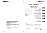
Figure 2.2 is a schematic diagram of the density detector.
As shown in the figure, the density detector consists mainly of a vibrator assembly, a capacitance
pickup electrode, and an amplifier.
Sample
Vibrator
Pick-up electrode
Preamplifier
Density signal
Temperature signal
Temperature
measuring element
Piezo-electric element
Vibrator cross sectional view of Density Detector
Figure 2.2
Schematic Diagram of Density Detector
The vibrator assembly consists of a sample path formed by connecting the ends of two thin
tubular vibrators whose upper ends are connected to a base. The connector incorporates
an RTD to measure the sample liquid temperature. The vibrator assembly also contains a
piezoelectric element to maintain vibration corresponding to the sample liquid density.
The capacitance pickup electrode installed between the two vibrating pipes detects the lateral
oscillation frequency of the vibrator.
IM 12T03A01-02E
4th Edition : Feb. 23, 2015-00
2-3
<2. PRINCIPLES OF OPERATION>
The amplifier converts the output of the capacitance pickup electrode into an AC voltage
to amplify it. This frequency signal is, together with the temperature signal from the RTD,
transmitted to the converter. A part of the frequency signal is fed back to the piezoelectric element
to maintain the vibrator oscillation.
2.2.2
Density Converter
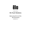
Figure 2.3 is a block diagram of the density converter.
As shown in the diagram, the density converter receives the density signal (frequency) F and
temperature signal (voltage) RT from the density detector and finally outputs a 4 to 20 mA
analog signal and 0 to 1 V DC signal corresponding to the liquid density converted to that at
reference temperature. The digital signals of densities at measuring temperature and reference
temperature, and measuring temperature and measuring temperature value are also output.
The converter circuit comprises three printed circuit boards. Changing displayed items or setting
constants are performed by keys or transfer switches on the front panel.
Frequency of Density (F)
Multiplexer
PC
EEPROM
CPU
Reference frequency
Temp. Signal
(RT)
R/V
Multiplexer
Ref. temp. Span
4 to 20 mA
TD
Digital Output
PC
200 V
Ref. temp. Zero
0 to 1 V
V/F
V/I
Zero
Span
PC
Integrator
PC
Key &
Display
Controller
Key
Driver
LED
Fail Alarm
PC
Figure 2.3
Block Diagram of Density Converter
IM 12T03A01-02E
4th Edition : Feb. 23, 2015-00
Blank Page
3.
3-1
<3. INSTALLATION, PIPING AND WIRING>
INSTALLATION, PIPING AND WIRING
Model DM8 vibration type density meter consists of a density detector and a density converter.
The density detector is generally installed in field and sampling piping is made to conduct
measuring liquid. The density converter is generally installed in the vicinity of the density detector.
It must not be installed in hazardous area. It can be installed in a control room, though it is far
away from the detector, receiving digital signal.
3.1
Installation of Density Detector
The density detector is shipped with a sampling unit if it is specified. For the detector without the
sampling unit, user should install sampling device suitable to measuring system.
3.1.1
Mounting Density Detector
The detector (without the sampling unit) should be installed vertically *1. The pipe mounting
bracket is applicable to vertical or horizontal pipe (JIS 50A) as shown in Figure 3.1 and 3.2.
*1:
The detector should be installed vertically to keep the vibrator pipe vertical.
(1)Pipe Mounting
The pipe mounting bracket is attached to the detector to mount it on a vertical pipe. For mounting
on a horizontal pipe, remove the mounting bracket from the detector to turn it 90° and fix it
again to the detector. Figure 3.1 shows installation on a vertical pipe and Figure 3.2 shows on a
horizontal pipe.
Figure 3.1 Installation on a Vertical Pipe
Figure 3.2 Installation on a Horizontal Pipe
IM 12T03A01-02E
4th Edition : Feb. 23, 2015-00
<3. INSTALLATION, PIPING AND WIRING>
3-2
(2)Bracket Mounting
This bracket is not the pipe mounting bracket. Release the four bolts (with spring washers) to
remove the pipe mounting bracket from the detector. Using the four bolts and spring washers,
fix the detector on the bracket as shown in Figure 3.4. Figure 3.3 shows position of holes to be
drilled on the bracket.
Unit: mm
70 ±0.2
4-ø9 Holes
40 ±0.2
Figure 3.3
Position of Holes on the Bracket
Density detector
Figure 3.4
Mounting on the Bracket
IM 12T03A01-02E
4th Edition : Feb. 23, 2015-00
3.1.2
3-3
<3. INSTALLATION, PIPING AND WIRING>
Sampling Unit for Vibration Type Density Meter
This section describes a sampling that is provided by user for the density meter.
The sampling equipment is equipped with valves, a thermometer, a flowmeter, etc., and is
located near to process pipe and the density detector.
The sampling equipment is used to provide good condition to measure liquid density, easy to
monitor measuring and maintenance condition such as calibration and cleaning the vibrator.
Install the sampling equipment according to the following. For details of piping from process to
the equipment, refer to the section 3.3.
(1)Flow Diagram
Figure 3.5 shows a flow diagram of a typical sampling equipment. Model VD6SM sampling unit of
Yokogawa is also designed according to this diagram.
FM
TI
PI
BV1
DD
SAMPLE IN
a
F
NV1
NV2
NV4
NV3
SAMPLE OUT
b
a'
STEAM IN
CONDENSATE OUT
Figure 3.5
a
Element specifications
F:
Strainer body; 316 SS
V1
V2
Element; 316 SS, or Ni (option)
PI: Pressure gauge, 0 to 1MPa or 0 to 2MPa, 316 SS
b'
a'
TI: Thermometer. 0 to 100 °C or 0 to 150 °C, 316 SS
FM: Flowmeter, tapered metal tube flowmeter, 1 to 10 L/min, 316 SS
ST1
BV1: Ball valve, 316 SS
NV1 to 4: Needle valve, 316 SS
DD:
Density detector
V1, V2: Valve
ST1: Steam trap
Flow Diagram
In Figure 3.5, each element of the sampling equipment is shown F (filter) is usually 80 meshes,
prevents a solid from entering into the sampling line. TI (thermometer), FM (flowmeter) and PI
(pressure gauge) are necessary to monitor measuring liquid. NV1 (needle valve) is required to
control flow rate of a sample liquid. BV1 (ball valve) and NV4 (needle valve) are used for stopping
measuring liquid when the vibrator is cleaned or calibration is performed using standard solution.
(The needle valve is also used for adjusting flow rate). NV2 (needle valve) and NV3 (needle
valve) are used for draining liquid from the vibrator or for picking up sample for manual analysis.
When viscosity of a measuring liquid is to be lowered, for example, the pour point of measuring
liquid is high, arrange the density detector and the liquid pipe should be warmed individually.
Steam pipe can be connected to the density detector and the liquid pipe can also be traced by
steam pipe. V1 (“stop” valve) is to supply the steam to the density detector and V2 (“stop” valve)
is to supply the steam to tracing pipe. ST1 (steam trap) is used to drain condensed water.
(Note1):Kind of valve used in the sampling equipment varies with the purpose of use. This instruction manual gives a detailed name of
equipment (for example, ball valve) used for limited purpose, and shows a general name within “ ” when equipment type is not
restricted (for example “stop” valve).
(Note2):Density Detectors of Model VD6D (general purpose type) and VD6DF (flameproof) have steam pipe connections, however,
Model VD6DS (sanitary use) has not the connections.
(Note3):Model VD6SM sampling unit, a product of Yokogawa, is applied to Model VD6D (general purpose type) or Model VD6DF
(flameproof type). It is not recommended for the Model VD6DS (sanitary use) used for food.
IM 12T03A01-02E
4th Edition : Feb. 23, 2015-00
3-4
<3. INSTALLATION, PIPING AND WIRING>
Density meter sampling unit
Anchor bolt
Drain pit
Concrete base
Figure 3.6
Installation Example for Sampling Unit (Model VD6SM)
(2)Note of Designing a Density Meter Sampling Unit
• Minimize liquid pipe length to improve response.
• Design the piping not to allow air bubbles to remain in the pipe which may cause an error.
• Piping should not have sharp bending where solids may accumulate.
• Maintenance such as cleaning should be made easily.
• Select element material most suitable for measuring liquid. Especially, for foodstuff
measurement, the selection should be done strictly.
(3)Installation of a Density Meter Sampling Unit
For the density detector with the sampling unit or with the sampling equipment user provided,
installing place must
• be near to sample tap on the main pipe.
• be free from vibration
• meet the ambient conditions specified by the hazardous area (when the detector is model
VD6DF flameproof type).
Moreover, the sampling unit should be fixed to a concrete base drained well.
(4)Removing a Packing Sheet for Transportation from the Density Detector
The vibrator is fixed to the amplifier case to avoid being damaged during transportation.
Remove the rubber sheet used for the fixing. The rubber sheet is inserted between the case
and the coupler of the vibrator assembly. Remove the sheet according the steps below. For
component names, refer to the section 4.1.1.
(a)Remove the lock with a hexagonal bar wrench. Release the cover by turning it
counterclockwise and pull it down not to touch the internal assembly.
(b)Remove the cover (with desiccant) from the vibrator.
IM 12T03A01-02E
4th Edition : Feb. 23, 2015-00
3-5
<3. INSTALLATION, PIPING AND WIRING>
(c)Release the lock-screw for the vibrator turning the screw counterclockwise completely
with a flat chip screw driver. Turn it enough, if not, the vibrator may touch the screw during
measurement causing an error. In addition, pay attention not to bend or damage the vibrator
because it is made of a thin pipe.
CAUTION
The vibrator tube has extremely thin wall, hence must be carefully handled.
Since assembling the vibrator tube requires special skill, the exchange of the vibrator should be
made by Yokogawa.
(d)Pull out the rubber sheet avoiding applying force to the vibrator (refer to Figure 3.7).
Lock-screw
Use flat blade screw-driver
to turn this screw fully counterclockwise.
Pull rubber sheet
in this direction
Rubber sheet
Pull out this rubber sheet
after loosening the set screw.
Figure 3.7
How to Remove the Rubber Sheet
(e)Remount the cover removed in the item (b). Also remount the cover in the item (a) to the
case and lock it.
Now the removing the rubber sheet finishes. Keep the rubber sheet which is necessary for
transportation of the density converter.
IM 12T03A01-02E
4th Edition : Feb. 23, 2015-00
3-6
<3. INSTALLATION, PIPING AND WIRING>
3.2
Installation of Density Converter
3.2.1
Installation Area
The density converter should be installed in the place described below;
• The vicinity of the sampling unit where maintenance or calibration is made easy. The density
converter is designed dustproof and rainproof structure so that it can be installed outdoors.
• However, when it is used with the Model VD6DF flameproof detector, it cannot be installed
the hazardous area, must be installed in the nonhazardous area. Further, when digital
output signal is used for a receiver, able length between the converter and the receiver
should be 10 m or less.
• Free from vibration.
Vibration may cause illegal contact in electric circuits.
• Avoiding from direct sunshine.
This instrument can be used in an ambient temperature of -10 to 55°C. However, direct
sunshine in summer may heat the instrument over the range.
• Free from corrosive gases and dusts.
The structure of this converter is dustproof and rainproof. However, for maintenance (with
opening front door of the converter), installation in better environment is recommended. For the
same reason, the followings are conditions for selecting installation area.
• Avoiding excessive humidity.
• Avoiding wide temperature variation.
3.2.2
Installation of Density Converter
The density converter can be installed on a panel or a wall or 2-inch pipe. The pipe should be
vertical to fix the mounting bracket on it (see Figure 3.8).
(Note):Mounting attitude is free from the converter performance. Mounting should be made of the following procedures.
Pipe mounting
hardware
Mounting bracket
Washer
Converter
Spring washer
Bolt (M8x10)
Bolt (M8x14)
Figure 3.8
Pipe Mounting
IM 12T03A01-02E
4th Edition : Feb. 23, 2015-00
3-7
<3. INSTALLATION, PIPING AND WIRING>
(1)Panel Mounting
The pipe mounting bracket should be removed from the converter before panel mounting.
Panel cutout dimensions are shown in Figure 3.9.
Before inserting the converter into front of the panel, remove the clumping brackets from both
sides of the converter case. After the case is inserted into a panel, remount the clumping brackets
on the same pace to hold the converter on the panel.
Figure 3.10 illustrates that the converter is mounted on a panel.
Unit: mm
212 ±1
275 ±1
Figure 3.9
Panel Cutout Dimensions
Figure 3.10
Panel Mounting
(2)Wall Mounting
Remove the pipe mounting bracket from the converter before wall mounting. Make two holes for
8 mm screws in a wall as illustrated in Figure 3.11.
222
Unit: mm
2-M8 Screws
Figure 3.11
Holes for Wall Mounting
Figure 3.12
Wall Mounting
Using two mounting brackets, mount the converter on the wall (see Figure 3.12).
IM 12T03A01-02E
4th Edition : Feb. 23, 2015-00
3-8
<3. INSTALLATION, PIPING AND WIRING>
(3)Pipe Mounting
Mounting bracket is applied to the pipe of nominal size 50A (diameter 60.5 mm). As shown in
Figure 3.13 mount the converter on the vertical pipe (inclination causes no problem).
Figure 3.13
Pipe Mounting
IM 12T03A01-02E
4th Edition : Feb. 23, 2015-00
3-9
<3. INSTALLATION, PIPING AND WIRING>
3.3Piping
The vibration type density meter requires the following piping;
(1) Sample liquid conduit
(2) Air piping for maintenance
(3) Steam piping
(4) Piping for air purge
Sample liquid conduit is a pipe to conduct measuring liquid to the density detector. Air piping
for maintenance is to obtain air to blow away liquid from the vibrator at maintenance (vibrator
cleaning, calibration with standard solution). Steam piping which is installed according to
requirement is to obtain a steam to heat the sample liquid conduit. Air purge piping is necessary
when the converter is installed in dusty environment.
The sample liquid conduit referred here indicates pipes between the main process pipe and the
sampling equipment. For piping within the sampling equipment, refer to Section 3.1.2.
3.3.1
Sample Liquid Conduit
This piping conducts the measuring liquid to the sampling unit. The main process pipe should
have two sampling taps (sample inlet and sample return) as shown in Figure 3.14. The sample
conduit from the sample inlet is connected to ‘SAMPLE IN’ of the sampling unit and the other
conduit from the sample return to ‘SAMPLE OUT’ of the sampling unit.
The piping procedure is as follows:
(1) Select the tap locations for the sample inlet and the sample return to make the pressure
difference between them become at least 0.1 MPa.
(2) The pipe length between the sample inlet and the SAMPLE IN should not exceed 10 m. Use
stainless steel pipe of nominal diameter 15 mm or Sch 40 to 80.
(3) Install stop valves and drain valves near the sampling unit.
Main process pipe line
Pin (Pressure at inlet)
Pout (Pressure at outlet)
2 MPa > Pin
≥ (Pout + 0.1 MPa)
Sample conduits
(10 m max.)
Tap valve
Drain valve
Stop valve
Drain valve
Sampling unit
for vibration type density meter
Figure 3.14
Sample Liquid Conduits
IM 12T03A01-02E
4th Edition : Feb. 23, 2015-00
3-10
<3. INSTALLATION, PIPING AND WIRING>
(4) Avoid sharp bending of the pipe to prevent accumulation of sludge.
Sampling unit
Main pipe
Sampling line
Sludge is likely to collect here.
Figure 3.15
3.3.2
Example of Wrong Piping
Air Piping for Maintenance
When cleaning the vibrator or calibrating the meter with standard solution, blow away liquid from
the vibrator by air pressure. Air should be clean and dried with 0.3 to 0.5 MPa G.
Mount a ‘stop’ valve and a ‘pressure regulator’ on the pipe from the air source, and fix a flexible
tube with a copper tube with outside diameter 10 mm should be provided for connecting with the
detector.
Connect the air pipe to the sampling unit only for cleaning the vibrator or calibration with the
standard solution.
Sampling unit
BV1
NV2
DD
NV4
NV3
Connect when cleaning the density detector
Air supply 300 to 500 kPa G
Flexible tube
Figure 3.16
Reducing Stop valve
valve
Air Piping for Maintenance
IM 12T03A01-02E
4th Edition : Feb. 23, 2015-00
3.3.3
3-11
<3. INSTALLATION, PIPING AND WIRING>
Steam Piping
This is installed to heat measuring liquid whose pour point is high, and to decrease its viscosity.
The sampling unit with steam trace pipes should be used for this purpose.
Connect a pipe from steam source to the sampling unit ‘STEAM IN’ inlet. The sample liquid
conduit also should have a steam tracer pipe. Steam of pressure 0.3 to 0.5 MPa and temperature
of 140 to 160°C is preferable.
Installing the tracer pipe for the sample liquid conduit should be performed after pressure
retentive and leak test of the conduit.
Notes for the tracer piping are as follows.
(1) The tracer pipe of the sample liquid conduit should be installed such that the entire conduit
can be heated. The pipe should also be covered with insulating material (see Figure 3.17).
(2) The steam trap discharge outlet should be open to the atmosphere (see Figure 3.18).
Heat insulating material
Trace pipe
Sampling line
Figure 3.17
Steam Tracer Pipe
Steam trap
Sampling unit
Drain pit
Figure 3.18
3.3.4
Piping at Steam Trap Discharge Outlet
Piping for Air Purge
If the density converter is installed in dusty environment, air purging is recommended.
Air purge should be performed continuously by clean dried air with pressure of 50 kPa G. Size
ø6 x ø4 mm copper or stainless pipe should be used to connect air source to the purge air inlet of
the converter.
The air inlet is Rc1/8 female connection. If specified, a connector for an Rc1/4 female or 1/4NPT
female screw is provided.
IM 12T03A01-02E
4th Edition : Feb. 23, 2015-00
<3. INSTALLATION, PIPING AND WIRING>
3-12
3.4Wiring
The vibration type density meter requires the following wirings:
(1) Wiring between analog output signal
(2) Wiring for analog output signal
(3) Wiring for digital output signal (10 m or less length is recommended).
(4) Wiring for contact output for abnormal status
(5) Wiring for power supplying
(6) Wiring for grounding
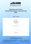
Figure 3.19 is a diagram of these wirings.
Detector
Special cable
Converter
A2
RED
A2
N.C
A3
BLUE
A3
C
A4
YELLOW
A4
A6
BROWN
A6
A5
GREEN
A5
B4
B5
WHITE
SG
RD
B5
G
G
RS-232C signal
TD
B4
GRAY
Closed when a
failure is detected or
the power fails.
Alarm
L1 L2
+
+
-
0 to 1 V DC
4 to 20 mA DC
• Density signal after being
converted to the reference
temperature state
• Density signal before being
converted to the reference
temperature state
• Temperature signal
Density signal after being
converted to the reference
temperature state
Power supply
Figure 3.19
Wiring Diagram
The cable inlet of the density detector is located at the bottom of the terminal box. The density
converter has five cable inlets and their size is 27 mm. A cable can pass any inlet of them (one
cable to one inlet). Figure 3.20 shows an example of allocated inlets.
Inlet of special cable
Analog output signal
Power supply
Digital output signal
Figure 3.20
Contact output for abnormal status
Cable Inlet of Density Converter
Figure 3.21 shows terminal arrangement of the density detector.
Terminals
B4
B5
A2
Figure 3.21
A3
A4
A5
A6
B4
B5
A2
A3
A4
A5
A6
Function
Output Frequency
Temperature Sensor
Power Supply for Pre-amp
Impressed Voltage for Pick-up Electrode
Earth Terminal
Terminal Arrangement of Density Detector
IM 12T03A01-02E
4th Edition : Feb. 23, 2015-00
3-13
<3. INSTALLATION, PIPING AND WIRING>
3.4.1
Wiring between Detector and Converter
This wiring is to be carried out with special cable of specified length. The cable is terminated as
illustrated in Figure 3.22. Pay attention not to stain or wet terminated.
Density converter
Density detector
B4
WHITE
B4
WHITE
B5
GRAY
B5
GRAY
A2
RED
A2
RED
A3
BLUE
A3
BLUE
A4
YELLOW
A4
YELLOW
A5
GREEN
A5
GREEN
A6
BROWN
Figure 3.22
A6
BROWN
DM8W Cable
< Connection to Density Detector >
Remove the cover of the terminal box, using the spanner in accessories, and insert the special
cable into the cable inlet. Connect each conductor to the respective terminals.
A flexible fitting is used at the inlet of the density detector *1 and the cable from the detector runs
though metal conduit to the duct. For Model VD6DF explosion-proof detector, wiring should be
made complying with the Recommended Practice.
The explosionproof flexible fitting for wiring should be used at the cable inlet (G3/4 female) of the detector.
*1:
The flexible fitting is not inevitable. The Detector not moved for usual check or maintenance does not require the flexible tube.
Figure 3.23 Wiring to Density Detector Terminals
Figure 3.24
Spanner for Open/closing
Terminal Box Cover
Cable
Terminal box case
Lock nut
Be sure to screw in
at least 12 mm (5 threads)
G3/4 screw (TIIS explosionproof)
3/4NPSM (FM explosionproof)
Explosionproof flaxible fitting
Figure 3.25
Explosion-proof Flexible Fitting
IM 12T03A01-02E
4th Edition : Feb. 23, 2015-00
3-14
<3. INSTALLATION, PIPING AND WIRING>
< Connection to Density Converter >
The density converter is installed in field or indoors (control room). The connector for passing
through cable should be sealed for air purge. The connector with a ring packing as shown in
Figure 3.26 should be used, or the inlet of metal conduit is filled with silicon sealing compound.
Duct or protective pipe for the cable should be provided to prevent the cable from damage.
Cable
Nut
Converter case
G3/4 screw
Lock nut
Flaxible fitting
Figure 3.26 Packing Gland Type Connector for Passing through Cable
Figure 3.27 Cable Inlet for Metal Conduit
Take the special cable into the converter from the leftmost inlet and connect the each conductor
to the respective terminals.
3.4.2
Wiring for Analog Output Signal
Output signal of 4 to 20 mA DC output (load resistance 550Ω or less) and 0 to 1 V DC (load
resistance 250 kΩ or more) are provided. Carry out either or both of wirings as necessary.
Shielded 2-conductor (for one signal) or 4-conductor (for two signals) cable are used for wiring.
For connecting the cable to the converter, remove the sheath of conductor about 50 mm from its
end, and attach a solderless lug for M4 screw omit. The shield of the cable should be grounded at
the receiving unit.
Wiring method (metal conduit and others) is same as that of Section 3.4.1.
3.4.3
Wiring for Digital Output Signal
The Model DM8C density converter outputs digital signals through RS-232C interface besides
analog signal (for details of digital signal, refer to “Standard Specifications” in Chapter 1).
When using this signal, use a shielded 3-conductor cable for wiring. Cable length from the
converter to a receiving unit should be 10 m or less.
Cable termination is same as that of Section 3.4.2, however, remove the sheath of conductor 80
mm from the end.
Wiring method is also same as that of Section 3.4.1.
3.4.4
Wiring for Abnormal Status Contact Output
When an error (see Table 4.2) occurs with an abnormality in the density measuring system, a
contact signal is output.
For wiring of this contact output, use 2-conductor cable. When connecting the cable to the
converter, remove the sheath of conductor 80 mm from its end and attach a solderless terminal
for M4 screw.
Wiring method is same as that of Section 3.4.1.
IM 12T03A01-02E
4th Edition : Feb. 23, 2015-00
3.4.5
3-15
<3. INSTALLATION, PIPING AND WIRING>
Wiring for Power Supply
This wiring is to supply the converter with power.
Use shielded 2-conductor cable for wiring. Cable termination and wiring method are the same as
those for analog output signal in Section 3.4.2.
3.4.6
Wiring for Grounding
As a rule, the case of the density detector and the density converter should be earthed.
The grounding terminal of the detector is located on the base for the mounting bracket, and of the
converter, on the bottom of the case. Perform wiring so that ground resistance is 100Ω or less
(Class D) using a wire of 2 mm2 nominal cross-sectional area.
IM 12T03A01-02E
4th Edition : Feb. 23, 2015-00
Blank Page
4th Edition : Feb. 23, 2015-00
4-1
<4. OPERATION>
4.OPERATION
4.1
Component Names and Function
4.1.1
Density Detector
Vibrator assembly
Case
Terminal box
Capacitance
pickup electrode
Terminal box cover
Oscillation
amplifier
Lock
Coupler
Vibrators
Cover
Figure 4.1
Piezoelectric
element
Lock-screw
(Keep loose during detector operation)
Density Detector
IM 12T03A01-02E
4th Edition : Feb. 23, 2015-00
4-2
<4. OPERATION>
4.1.2
Density Converter
Data Display: Function No. and data are displayed.
Front door
Function No. display
Data display
Fastener (Nyratch)
Internal assembly fixing screw
(for transportation)
INCR ▲ key:
Increases the number of a
flashing digit.
SET key:
Used to enter a displayed
data.
Data sheet
SHIFT ► key:
Pressed thi key, displayed
number flashes. Flashing
digit shifts right with every
pressing of the key.
FUNCTION No. key
Mode transfer switch
Cover of terminal board
DSPL (measuring mode):
Mode for normal operation. In this mode, density at the reference
temperature, density at measuring temperature or measuring
temperature value is displayed by transferring function No.
CAL (calibration mode):
Mode for calibration
MAINT (maintenance mode):
Mode for check of operating condition; setting a detector constant,
a reference temperature.
Figure 4.2
Component Names of Density Converter
IM 12T03A01-02E
4th Edition : Feb. 23, 2015-00
4-3
<4. OPERATION>
4.2Operation
4.2.1
Operation Mode
Operation of the Model DM8 vibration type density meter ruled by the mode as shown in Table
4.1. Measuring mode (DSPL), calibration mode (CAL) and maintenance mode (MAINT) are
transferred with the mode transfer switch.
Table 4.1
Operation Modes and Function No.
MODE SW
Measuring
mode
(DSPL)
Calibration
mode (CAL)
Maintenance
mode
(MAINT)
FUNCTION
NO.
No display
1
2
Contents
Display
Displays density (at reference temperature)
Displays density (measured value)
Displays measuring liquid temperature
3
4
5
6
7
8
9
A
Sets density of calibration solution 1
Sets temperature of calibration solution 1
Sets temperature coefficient of calibration solution 1
Starts calibration 1 (press SET key)
Sets density of calibration solution 2
Sets temperature of calibration solution 2
Sets temperature coefficient of calibration solution 2
Starts calibration 2 (press SET key)
1.
2.
3.
4.
5.
6.
7.
8.
9.
A.
B.
C.
D.
Cancellation of protection (enter 77)
Displays frequency (density)
Displays frequency (temperature)
Checks output signal
Checks LED (press SET key)
Sets low limit of the output range
Sets high limit of the output range
Sets reference temperature of measuring liquid
Sets temperature coefficient of measuring liquid
Sets detector constant A
Sets detector constant B
Displays detector calibration coefficient C (span)
Displays detector calibration coefficient D (zero)
g/cm3
g/cm3
°C
□.□□□□ g/cm3
□□□.□ °C
-□□□x10-5 g/cm3/°C
CAL-1 (displays density after calibration)
□.□□□□ g/cm3
□□□.□ °C
-□□□x10-5 g/cm3/°C
CAL-2 (displays density after calibration)
77
Hz
Hz
□□□ %
- LED - (flash 5 times)
□.□□□□ g/cm3
□.□□□□ g/cm3
□□□.□ °C
-□□□x10-5 g/cm3/°C
□□□□□
□□□□□
(1)Measuring mode (DSPL): Mode for normal operation
An analog output in this mode is density value at the reference temperature.
Moreover, density value at measuring liquid temperature and temperature of measuring liquid are
digitally output. The density value at the reference temperature (without function No. display), the
density value at measuring liquid temperature (No.1) or the measuring liquid temperature (No.2)
can be displayed by selecting function No. Use FUNCTION key to select the FUNCTION No.
(2)Calibration mode (CAL): Mode for calibration. Sets or specifies data required
for calibration.
During this mode the analog and digital outputs are held (at the values just before the holding).
However, digital data output stops during calibration function No. ‘6’ or ‘A’.
When calibration computation ends holding is released and measured data are again output until
function No. ‘6’ or ‘A’ is transferred to another No.
IM 12T03A01-02E
4th Edition : Feb. 23, 2015-00
4-4
<4. OPERATION>
Digital signal *1
Measuring mode (DSPL)
Analog signal
Measured Measured
value
value
Measured
value
Maintenance mode (1)
(MAINT)
(1)
Hold
(1)
Hold
(2)
Hold
Hold
Hold
Transfer to
Calibration mode
Measured
value
Calibration mode (CAL)
Calibration start
While in calibration
computation
Output stop
*2
Calibration end
Calibration mode
function No. transfer
or waiting for mode
transfer
Measured
value
Measured
value
Function No.
transfer (2)
(2)
Maintenance mode (3)
(MAINT)
(3)
Measuring mode (DSPL)
*1:
*2:
Hold
Measured
value
Measured
value
(3)
Measured
value
The density value after temperature conversion, density value at the measuring temperature and measuring liquid temperature
are transmitted in digital form. (Only the density value after temperature conversion is transmitted in analog form.)
The density converter displays CAL-1 or CAL-2.
Figure 4.3
Digital and Analog Signal Output Statuses
Eight function Nos. from ‘3’ to ‘A’ are provided in the calibration mode (see Table 4.1). Among
them, ‘6’ and ‘A’ are to specify the calibration computation and others are to input data required
for the calibration.
Function No. ‘3’: Sets density of calibration solution 1
Density value (g/cm3) of a calibration solution for one-point calibration or 1st calibration of
two-point calibration can be input. The input density is a data at the reference temperature.
(Note):If relation between temperature and density is well known, a density at a temperature can be set. However, the density data at
the reference temperature is recommended to achieve accurate calibration.
Function No. ‘4’: Sets temperature of calibration solution 1
Input the temperature of the calibration solution 1 of which density at the reference
temperature is set at ‘3’.
Function No. ‘5’: Sets temperature coefficient of calibration solution 1
Enter the value which is -100000 times the temperature coefficient (g/cm3/°C) of the liquid
for calibration 1.
(Note):The temperature coefficient -0.00086 g/cm3/°C becomes the value 086.
Function No. ‘6’: Starts calibration 1 (press SET key)
Pressing “SET” key executes calibration computation, or also executes the first calibration
of the two-point calibration.
(Note):For calibration procedure, refer to Section 4.4.
Function No. ‘7’: Sets density of calibration solution 2
Density data (g/cm3) for the 2nd calibration (calibration solution 2) of two-point calibration
can be input. As a rule, the input density is data at the same reference temperature as that
of ‘4’.
(Note):If relation between temperature and density is well known, a density at a temperature can be input. However, the density data at
the reference temperature which is same as that of ‘4’ is recommended to achieve accurate calibration.
Function No. ‘8’: Sets temperature of calibration solution 2
IM 12T03A01-02E
4th Edition : Feb. 23, 2015-00
4-5
<4. OPERATION>
Enter the temperature of calibration solution 2 of which density at the reference temperature
is set at ‘7’.
Function No. ‘9’: Sets temperature coefficient of calibration solution 2
Enter the value which is -100000 times the temperature coefficient (g/cm3/°C) of the
calibration solution 2.
Function No. ‘A’: Starts calibration 2 (press SET key)
Pressing “SET” key executes 2nd calibration computation of two-point calibration.
(3)Maintenance mode (MAINT): Mode for adjusting and checking operating
conditions.
During this mode, analog and digital outputs are held (at the value just before holding).
Function No. in maintenance mode is from ‘1.’ to ‘D.’ (see table 4.1).
Function No. ‘1.’: Cancellation of protection (enter 77)
Function to avoid data changing due to carelessness. When “0” is displayed, a function No.
is not entered. To release the protection, display “77” and press “SET” key. To reactivate the
protection, display "78" and then press the "SET" key. To avoid the possibility of hindering
normal measurement, when releasing or reactivating the protection, do not press the "SET"
key after displaying other numbers. In addition, the reactivation of protection does not take
effect until you perform another operation (e.g., change the function No. to '2') after you
release the protection.
Function No. ‘2.’: Displays frequency (density)
Checks operation of this converter. Frequency corresponding to measured density are
displayed. When the converter is normal, the frequency ranges from 600 to 700 Hz to 1000
or 1500 Hz.
(Note):Displayed frequency varies with measured density, liquid temperature and detector constant. If density is 0.5 to 2.0 g/cm3,
temperature is 25 °C, detector constant (A) is 17074 and detector constant (B) is 36384, the frequency is 640 to 1400 Hz for
normal operation.
Function No. ‘3.’: Displays frequency (temperature)
Checks operation of this converter. A frequency signal converted from liquid temperature
voltage is displayed. If temperature is 25 °C, the frequency is about 25000 to 35000 Hz for
normal operation.
Function No. ‘4.’: Checks output signal
Checks zero point and span of an analog output signal.
(Note):The data at shipping is described in a data sheet in the converter.
Function No. ‘5.’: Checks LED (press SET key)
Function to check LED data display. When “SET” key is pressed, all displays flash five times
if it is normal.
Function No. ‘6.’: Sets low limit of the output range
Sets a low limit density value (g/cm3) of an analog output range.
(Note):Set the value so that high limit - low limit is greater than equal to 0.05 g/cm3. You cannot enter a value that fails to meet this
condition.
Function No. ‘7.’: Sets high limit of the output range
Sets a high limit density value (g/cm3) of an analog output range.
(Note):Set the value so that high limit - low limit is greater than equal to 0.05 g/cm3. You cannot enter a value that fails to meet this
condition.
Function No. ‘8.’: Sets reference temperature of measuring liquid
Sets a reference temperature (°C) of measuring solution.
Function No. ‘9.’: Sets temperature coefficient of measuring liquid
Sets the value which is -1 x 10⁵ (= -100000) times the temperature coefficient of measuring
solution (g/cm3/°C) to change it to plus integer.
(Note):Purified water is an exception; its maximum density is at approx. 4 °C. Generally, temperature coefficients of any liquids are
minus number.
Function No. ‘A.’: Sets detector constant A
IM 12T03A01-02E
4th Edition : Feb. 23, 2015-00
<4. OPERATION>
4-6
Sets the detector constant A. Since the detector constant A is an inherent characteristic of
the detector, this is indicated in each detector.
(Note)Detector constant A changes with each calibration.
Function No. ‘B.’: Sets detector constant B
Sets the detector constant B. Since the detector constant B is also an inherent characteristic
of the detector, this is indicated in each detector.
Function No. ‘C.’: Displays detector calibration coefficient C (span)
Indicates either the one-point or two-point calibration has been performed. 1 is indicated for
one-point calibration and calibration coefficient (span) for two-point.
Function No. ‘D.’: Displays detector calibration coefficient D (zero)
Indicates either the one-point or two-point calibration has been performed. 0 is displayed for
one-point calibration, and calibration coefficient (zero point) than 0 is displayed for two-point
calibration.
IM 12T03A01-02E
4th Edition : Feb. 23, 2015-00
4.3
4-7
<4. OPERATION>
Preparation for Measurement
4.3.1
Check for Piping
Check the following points.
• Is the pressure difference 100 kPa or more between both sampling tap?
• Is the diameter of the sampling pipe appropriate? Is length of the inlet pipe too long?
(Note):The sample inlet pipe is usually JIS 15A or Sch 40 to 80 stainless steel pipe.The pipe length between sampling tap and the
detector should be 10 m or less.
• Are valves and meters (pressure gauge, thermometer) provided in the sampling pipe for
normal operation and maintenance?
• Is air for cleaning the detector provided?
(Note):Dried 0.3 to 0.5 MPa G air is requires for cleaning the detector.
• Can heating steam for the density detector be stopped during operating time?
4.3.2
Check for Wiring
Check that whole wiring of the measuring system including a receiving unit (for example,
recorder) is completed.
When the detector is explosion-proof type, place the terminal box cover as completely as before
if it is once released.
4.3.3
Measuring Liquid Flow
Operating procedure for introducing sampling liquid is explained here, assuming the piping in
Figure 3.5 in Section 3.1.2 is equipped. When pipe arrangement is different from that of Figure
3.5, carry out corresponding operations described here. It is important that air bubble does not
remain in the pipe.
If calibrating is to be made with standard solution, conduct the measuring liquid after calibration
work to omit cleaning the vibrator. However, if pressure compensation is to be made (see Section
4.3.6), conduct the measuring liquid to obtain compensation value beforehand.
(1) First, set each valve in the sampling unit as follows.
Ball valve “BV1”: Fully closed
Needle valve “NV1”:
Fully closed
Needle valve “NV2”:
Fully closed
Needle valve “NV3”:
Fully closed
Needle valve “NV4”:
Fully closed
* ‘Stop’ valve “V1” *:
Fully closed
* ‘Stop’ valve “V2” *:
Fully closed
(Note):V1 and V2 marked by * are used only for steam tracer.
(2) For the sampling conduit with the steam tracing pipe, open the steam main valve to heat the
sampling conduit.
Keep the ‘stop’ valve “V1” closed, not heat the detector if it is not remarkably cooled.
(3) Prepare a sample receptacle (liquid pan) just under the ‘drain’ valve provided in the sample
conduit. First, fully open the ‘drain’ valve, then gradually open the ‘tap’ valve.
When the sample liquid begins to flow out of the drain valve, close the ‘tap’ valve.
(4) The same procedure as (3) should be made for the sample return conduit. Prepare a
sample receptacle (liquid pan) just under the drain valve. First, fully open the ‘drain’ valve,
then gradually open the ‘stop’ valve. When the sample liquid begins to flow out of the ‘drain’
valve, close the ‘stop’ valve.
IM 12T03A01-02E
4th Edition : Feb. 23, 2015-00
4-8
<4. OPERATION>
(5) Fully open “BV1” and “NV4” and half open “NV1” in the sampling unit. Close ‘drain’ valve
opened in (3). Gradually open the ‘tap’ valve located on the sample inlet conduit. As sample
begins to flow out of the ‘drain’ valve on the sample return conduit, fully open the ‘stop’ valve
and fully close the ‘drain’ valve when no retaining air is found in the liquid.
(6) Open “NV2” to exhaust retaining air in the pipe. When the sample liquid without air flows out
from the ‘drain’ port, fully close the “NV2”.
(7) Adjust opening of NV1 to make sample flow rate approx. 5 L/min for the detector.
Flow rate shown by FM in the VD6SM sampling unit of Yokogawa varies according to
viscosity of sample. If the viscosity of sample liquid becomes higher, flow rate indication also
becomes higher than real flow rate (see Figure 4.4).
Specific gravity of liquid (ρ=0.85)
25 cP
20 cP
30 cP
40 cP
50 cP 35 cP
15 cP
60 cP
10 cP
5 cP
1 cP
Indication of flowmeter (L/min)
20
15
10
5
0
5
10
15
Actual flow rate (L/min)
Figure 4.4
20
Flow Rate Characteristics for Sample Liquid Viscosity
(8) Confirm that the sample liquid temperature T and pressure P are in the specified range.
(9) Visually check that the sample liquid is not leaking from the connections.
4.3.4
Turning ON the Power
Supply the converter and a receiving unit (recorder, computer, etc.) with power with specified
voltage and frequency. The receiving unit should be ready to receive the data and controller
should be adjusted to perform accurate control.
4.3.5
Data Input
Set the mode transfer switch to “MAINT” (maintenance mode) and input data to the function No.
‘6.’, ‘7.’, ‘8.’, ‘9.’, ‘A.’ and ‘B.’. For details of data to be input, refer to Section 4.2. Data is input with
“SHIFT►”, “INCR▲” and “SET” keys. For details of these keys operation, refer to Figure 4.1.2.
When temperature coefficient of measuring liquid that is to be input into function No. ‘9.’ is
unknown jet, refer to ‘4.4.2 Calibration with Sample Liquid (2)’.
IM 12T03A01-02E
4th Edition : Feb. 23, 2015-00
4.3.6
4-9
<4. OPERATION>
Pressure Compensation
Pressure compensation means to compensate the shift generated by measurement under
operating pressure. The compensation should be carried out as necessary only for calibration
under atmospheric pressure.
Measured value is affected up to +0.00005 g/cm3 by 100 kPa pressure variance.
Therefore, for liquid under pressure approximating to the atmospheric pressure calibrated
value under atmospheric pressure can be used. Pressure compensation is to be carried out to
minimize effects generated by high operating pressure.
Compensation data is obtained by conducting sample liquid. Measure the data according to the
following procedure when the liquid density is stable. The procedure assumes that sample liquid
is already conducted according to Section 4.3.3.
(1) Fully open the needle valve “NV4” and read P from the pressure gauge. At the same time,
obtain density at the reference temperature indicated on the density converter.
(2) Fully close the ball valve “BV1”, and open the needle valve “NV3” to equalize the sample
liquid pressure in the detector to the atmospheric pressure. Obtain density at the reference
temperature indicated on the density converter.
(3) Calculate the compensation data using the densities obtained in (1) and (2).
Compensation data (g/cm3) =
Density under working pressure – density under atmospheric pressure
When calibration the compensation data should be subtracted from the density value of the
standard solution.
FM
TI
PI
BV1
DD
SAMPLE IN
a
F
NV1
NV2
NV4
NV3
SAMPLE OUT
b
a'
STEAM IN
CONDENSATE OUT
Figure 4.5
a
Element specifications
F:
Strainer body; 316 SS
V1
V2
Element; 316 SS, or Ni (option)
PI: Pressure gauge, 0 to 1MPa or 0 to 2MPa, 316 SS
b'
a'
TI: Thermometer. 0 to 100 °C or 0 to 150 °C, 316 SS
FM: Flowmeter, tapered metal tube flowmeter, 1 to 10 L/min, 316 SS
ST1
BV1: Ball valve, 316 SS
NV1 to 4: Needle valve, 316 SS
DD:
Density detector
V1, V2: Valve
ST1: Steam trap
Flow Diagram
IM 12T03A01-02E
4th Edition : Feb. 23, 2015-00
4-10
<4. OPERATION>
4.4Calibration
The vibration type density meter should be calibrated as occasion demands to keep the specified
accuracy.
Calibration has two methods: one-point calibration and two-point calibration, and each method is
carried out by either sample liquid or standard solution. The calibration with sample liquid is not
requiring stopping operation and pressure compensation resulting in accurate measurement. On
the other hand, in calibration with standard solution, the solution density is once determined at
the fixed value, density measurement of sample liquid should not be repeated at a laboratory.
The one-point calibration is equal to that omitting the 2nd calibration two-point calibration, so, the
two-point calibration using standard solution and sample liquid is described as follows. Since the
following is described assuming that the density converter is installed in the vicinity of the density
detector, for the connector installed away from the detector, please edit the manual for it and
carry out the calibration according to the manual.
4.4.1
Calibration with Standard Solution
Provide two kinds of standard solution whose density at reference temperatures is already known
*1. One density (standard solution 1) should be near to the low limit of the measuring range and
the other to the high limit (standard solution 2). Temperature coefficients (g/cm3/°C) of these
standard solutions should be obtained beforehand.
*1:
When measuring the density of the standard solution, use a hydrometer whose minimum scale is 0.0005 kg/cm3.
Calibration should be made in the following procedure. During calibration, only the density
detector and the density converter are to be driven and the unit to receive output signals from the
converter can remain stopped.
(1) Set the converter to “CAL” mode and input data corresponding to function No. ‘3’, ‘4’, ‘5’, ‘7’,
‘8’ and ‘9’. For pressure compensation, subtract the compensation value obtained in Section
4.3.6 from density of standard solution, and set them to function No. ‘3’ and ‘7’.
(Note)When the compensation value is a minus number, the set value becomes large than the standard solution density.
(2) Purge the inside of the vibrator with air as follows. Fully close the ball valve “BV1” and the
needle valve “NV4” in the sampling unit. Fully open the needle valve “NV2” and “NV3”,
connect an air pipe to the outlet port of the needle valve “NV3” and blow air for one or two
minutes. Pneumatic pressure should be 0.2 to 0.3 MPa*1.
*1:
For sample liquid remains in the vibrator, blow it out by 0.05 MPa G pneumatic pressure, and increase the pressure up to 0.2 to
0.3 MPa to dry the inside of the vibrator.
(3) Pouring 18 to 20 mL of standard solution 1 into the vibrator, avoiding air bubble entering it is
described here.
Firstly, remove the blind plugs from the pouring ports for the standard solution (two places)
located on the detector base plate. Secondly, pour the standard solution into the pouring
port using the injector (accessory) so that the solution flows along the inner wall of the
vibrator tube. Using the pouring port near to the sample inlet is recommended. If the injector
is stained, clean it with alcohol.
(4) Read the measured density value at the reference temperature. It is displayed with the
mode selector switch 3 set to “DSPL” and function No. not displayed.
(5) Since calibration with standard solution 1 is made two times, blow out the used standard
solution from the vibrator. Before blowing, plug the pouring orts (two places), and blow air
according to (2).
(6) Carry out the operations of (3) and (4) to confirm that the same results as that of (4) is
achieved.
(Note):If the result differs from (4), repeat the operations of (3) and (4).
(7) For the calibration 1 computation, press “SET” key at the function No. ‘6’. ‘CAL-1’ flashes
during computation and the density at the reference temperature is displayed after the
computation finishes (NOTE (a) ). Check that this value is the correct density (NOTE (b) ) of
the standard solution 1.
IM 12T03A01-02E
4th Edition : Feb. 23, 2015-00
4-11
<4. OPERATION>
NOTE
(a) Time for calibration computation varies with density value difference between pre-calibration
and after-calibration. The larger the difference is, the longer the time is. It can take up to
about 7 minutes
(b) The density value after calibration doesn’t always coincide with the density of the standard
solution 1 even if they are compared in the same temperature.
Especially when the solution temperature during calibration largely different from the
reference temperature an error is apt to occur.
However, the error is usually within allowable range, if it is too large, examine each set
value.
(8) The first calibration is finished by (7). Then, use the standard solution 2 carry out the second
calibration whose procedure is same as the first calibration. Repeat the operations of (1) to
(7). For the calibration computation, set the function No. to ‘A’ (CAL-2 display flashes seven
times).
When the second calibration is finished, purge the standard solution from the vibrator and screw
the blind plug into the pouring port, fully close the needle valves “NV2” and “NV3” and remove the
connected air pipe.
4.4.2
Calibration with a Sample
Calibration with sample liquid should be made according to the following procedure.
(1) Sample the measuring liquid which is measured by a hydrometer. Sampling should be
made when the liquid density is stable.
NOTE
The density of the sample liquid should not change between sampling the liquid and finishing the
first calibration.
(2) Measure the density using the hydrometer and the temperature of the sampled liquid.
Examine the temperature coefficient if it is not known. Using densities at high temperature
(reference temperature + approx. 5°C) and low temperature (reference temperature approx. 5°C), the temperature coefficient should be calculated as following.
Temperature coefficient (g/cm3/°C) =
(Density at high temperature – Density at low temperature)
/Difference between high and low temperatures
(Note):The density values should be those at the reference temperature as far as possible.
(3) Set the mode transfer switch of the converter to “CAL” and input the data corresponding to
function No. ‘3’, ‘4’ and ‘5’.
(4) For specify the first calibration computation, select the function No. ‘6’ and press “SET” key.
‘CAL-1’ display flashes during computation and the density at the reference temperature is
displayed after computation.
Confirm that the density value is almost the same as that of measured at (2).
(5) Before carrying out the second calibration, change the density of the measuring solution in
the sampling unit. Perform the operations of (1) to (4). In the operation corresponding to (3),
input the data to function No. ‘7’, ‘8’ and ‘9’. In the operation corresponding to (4), use the
function No. ‘A’ to specify calibration computation.
IM 12T03A01-02E
4th Edition : Feb. 23, 2015-00
4-12
<4. OPERATION>
4.4.3
Calibration Error
If an error indication (E005 in the first calibration or E006 in the second calibration) is displayed
when calibration computation finishes, examine the data input to function No. ‘3’, ‘4’, ‘5’, ‘7’, ‘8’ or
‘9’ and repeat the computation using the incorrect data.
4.5Operation
4.5.1
Operation Procedure
Start the density measuring system, and monitor operating conditions for a while to confirm
that there is no abnormality. Adjustment for the density measuring system during operation is
unnecessary, however, daily check of liquid flow rate and pressure is preferable. When the steam
tracing pipe is installed in the sampling unit, do not heat the detector.
If an error indication is displayed, make a countermeasure immediately. Errors are listed in Table
4.2.
Table 4.2
Display
Error Table
Contents
Error Release and Remedy
E001
Abnormal detector density signal
E002
Abnormal detector temperature sinal
When cause is removed
E003
Abnormal on converter
E004
Out of measuring temperature
E005
Abnormal first calibration
E006
Abnormal second calibration
Check and reset the data required for
calibration.
E007
Illegal data of EEPROM
Check and reset the loaded constant
When cause is removed
NOTE
E001, 002, 003, 004 and 007 are cancelled temporally by pressing the FUNCTION No. key
in maintenance or calibration mode, however in the measuring mode, the error indication is
displayed again. These errors are detected only in the measuring mode.
E005 and E006 are errors that occur only in the calibration mode. You can clear these errors
by pressing the "SET" key. After that, the density at the reference temperature by the previous
calibrating data is displayed.
4.5.2
Check of Measured Density Value
It is recommended that measured density values are checked at intervals of several weeks to
determine the period for calibration and cleaning.
(1) Measure the density using a hydrometer to compare it with the density indication (at the
reference temperature) on the vibration type density meter. When sampling the liquid, check
the pressure and the temperature are not largely different from those of the normal state.
(2) Measure density correctly at the reference temperature which is same as the sample liquid
temperature.
(3) Compare the density measured at (2) with the displayed value when sampling the liquid. If
the difference of them exceeds the allowable error range, clean the vibrator.
For cleaning procedure, refer to Section 5.1.1.
4.5.3Shutdown
When shutdown sample following steps and the vibration type density meter also stops, drain the
sample from the detector.
IM 12T03A01-02E
4th Edition : Feb. 23, 2015-00
5-1
<5. MAINTENANCE>
5.MAINTENANCE
5.1
Daily Inspection/Maintenance
5.1.1
Cleaning the Vibrator in the Detector
Dirt particles may be deposited on the inner wall of the vibrator pipe, depending upon the nature
of the process liquid. This can cause an error. Clean the pipe at regular intervals in the following
manner.
(1) Close valves BV1 and NV4 and open NV2 and NV3.
(2) Connect the air pipe to the outlet of the needle valve NV2. Purge the sample liquid in the
vibrator from the drain port of the needle valve NV3 by blowing 0.05 MPa G air.
(3) Remove the blind plugs from the pouring port of the standard solution (two places) and pour
cleaning liquid about 200 mL into the vibrator.
(4) After a while, fix blind plugs again on the pouring ports and purge the cleaning liquid in the
vibrator as described in (2). Wash the inside of the vibrator pipe with a brush (accessory) as
shown in Figure 5.1.
FM
TI
PI
BV1
DD
SAMPLE IN
a
F
NV1
NV2
NV4
NV3
SAMPLE OUT
a'
STEAM IN
CONDENSATE OUT
Figure 5.1 Cleaning the Vibrator
b
a
V1
b'
Element specifications
F:
Strainer body; 316 SS
Element; 316 SS, or Ni (option)
PI: Pressure gauge, 0 to 1MPa or 0 to 2MPa, 316 SS
a'
TI: Thermometer. 0 to 100 °C or 0 to 150 °C, 316 SS
FM: Flowmeter, tapered metal tube flowmeter, 1 to 10 L/min, 316 SS
ST1
BV1: Ball valve, 316 SS
NV1 to 4: Needle valve, 316 SS
DD:
Density detector
V1, V2: Valve
ST1:
Steam trap
V2
Figure 5.2 Flow Diagram
(5) Remove the blind plugs again from the pouring ports of the standard solution and pour the
cleaning liquid about 200 mL. After a while, fix the blind plugs and purge the sample liquid
by blowing 0.05 MPa G air. After the liquid is blown out, increase the air pressure up to 0.2 to
0.3 MPa G blowing air for 2 or 3 minutes to dry the inside of the vibrator.
5.1.2
Exchange of Desiccant in the Detector
Desiccant is used to protect the oscillation amplifier in the detector from humidity.
Checks the detector terminal box one or two times a year and replace the desiccant if humidity is
detected. Two desiccants are provided as accessories. For the explosion-proof detector, confirm
that there are no explosive gases using a gas detector before removing the terminal box cover.
IM 12T03A01-02E
4th Edition : Feb. 23, 2015-00
5-2
<5. MAINTENANCE>
5.2Troubleshooting
Experiences are required for repair of the vibration type density meter; after parts are replaced,
adjustment may be necessary. If trouble occurs, as a rule, repair should be made by Yokogawa.
In this case, detailed information on abnormal phenomena will be effective for speedy recovery.
Searching method for abnormality is explained below. For the explosion-proof detector, confirm
that there are no explosive gases using a gas detector before removing the terminal box cover.
5.2.1
Checking the Vibrators
Remove the cover of the detector, so that the vibrator can be visually inspected.
Carefully check the entire surface of the two tubular vibrators. If they have dents, scratches,
holes or show signs of the sample liquid leakage, the vibrator assembly should be exchanged.
(CAUTION)
Make sure that the lock-screw is not in contact with the vibrator assembly.
CAUTION
The vibrator tube has extremely thin wall, hence must be carefully handled. Since assembling the
vibrator tube requires special skill, the exchange of the vibrator should be made by Yokogawa.
5.2.2
Checking the RTD
Measure electrical resistance between the terminal A2 and A3. When the RTD is normal, the
resistance shows the value indicated in the following table.
Table 5.1
Resistance at each temperature of RTD (Pt 1000Ω)
Temperature (°C)
10
15
20
25
30
35
40
45
50
Resistance (Ω)
1039.0
1058.5
1077.9
1097.3
1116.7
1136.1
1155.4
1174.7
1194.0
IM 12T03A01-02E
4th Edition : Feb. 23, 2015-00
5.2.3
5-3
<5. MAINTENANCE>
Checking the Oscillation Amplifier
First, visually inspect the capacitance pickup electrode. This electrode should be installed near
the vibrator with a small gap between them. Without this gap, the electrode will not function
properly. If there is moisture or dirt between the electrode and vibrator, clean the gap with a cloth.
Take care not to damage the vibrator.
Then, check the electrical circuitry using a DC voltmeter and other appropriate measuring
instruments. For the types of instruments and the checkpoints, see Figure 5.3.
Terminal
Box
Vibrator output
wavefarm between
B4 and B5 when
density detector is
operating normally.
Black A5
B
White A6
6V
D8
1mS
A
IN
R Red
B5
Piezoelectric
element
Blue
A2
Yellow
B Black
D
A3
C
Green A4
Red
B4
Brown Y1
Pt1000
Case ground
Green
Y2
White Y3
Check point
Measuring instrument
Measuring conditions
Normal value
Remedial measure
for abnormal value
1
A5 – B5 DC voltmeter
12 V±10 %
Check converter INPUT
2
200 V±10 %
assembly.
3
A6 – B5 the meter input impedance
B – B5 should be at least 10 MΩ
5.8 to 6.4 V
Replace D8.
4
IN –
Check pickup electrode.
5
B4 – B5 Oscilloscope
∞ (X 10 kΩ Range)
Disconnect leadwires from terminals 6 to 8 V p-p
Check for defective circuit
6
R – B5
IN, R, and B, on PCB, connect an
components and replace
7
A – B5
oscillator (0 to 2000 Hz, output 5 V), 200 mV p-p
8
C – B5
and apply an input of 100 mV rms.
9
D – B5
For measurement of 2 ,
Multimeter
DC voltmeter
Lower 100 mV rms input
150 to 200 V p-p
them.
4 to 6 V p-p
-3 to 0 V
F0502.ai
(Note):Regarding to repair parts, consults with service personnel.
Figure 5.3
Oscillation Amplifier Check Points
IM 12T03A01-02E
4th Edition : Feb. 23, 2015-00
Blank Page
Customer
Maintenance
Parts List
Item
Model VD6D, VD6DF, VD6DS
Liquid Density Detector
Part No.
Qty
Description
1
2
3
4
5
—
K9000SK
K9000CC
K9000DB
L9818JB
1
1
2
2
4
Terminal Box Cover
Cover
Plug (for Models VD6D and VD6DF)
Plug (for Model VD6DS)
Gasket (for Model VD6DS)
6
7
8
9
10
G9303AR
G9303BA
G9303NE
K9000AK
K9324PC
1
1
2
1
1
O-Ring
O-Ring
O-Ring (for Model VD6DS)
Chain Assembly (for Model VD6DF)
Desiccant (2 packs)
11
12
13
14
K9000AC
D0117XL-A
L9826AG
L9826AC
1
2
2
1
Clamp
U-Bolt Assembly
Bracket
Bracket
©Copyright 1999, 1st Edition: 1987 (YK)
Subject to change without notice.
CMPL 12T3E1-01E
5th Edition : Apr. 2009 (YK)
2
Accessories Assembly
Accessories Assembly
Item
Part No.
Qty
1
2
3
4
5
K9000PQ
L9827AR
K9000NB
L9827AE
E9135GZ
1
1
1
1
1
6
7
K9324PC
K9003NG
1
1
CMPL 12T3E1-01E
Description
Accessories Assembly
Brush
Injector
Allen wrench
Spanner
Desiccant (2 packs)
O-Ring Set (used for item 6 and 7 in page 1)
5th Edition : Apr. 2009 (YK)
Customer
Maintenance
Parts List
Model DM8C
Liquid Density Converter
1
3
4
[Style D]
2
5
6
Item
Part No.
Qty
Description
1
2
3
4
5
K9005CA
K9005AA
K9000YR
K9005YR
K9141TV
1
1
1
1
1
Digital Board Assembly
Main Board Assembly
Cable Assembly (red)
Cable Assembly (yellow)
Fuse (250 V, 3 A)
6
K9000ZE
1
Transformer Assembly
©Copyright 1999, 1st Edition: 1987 (YK)
Subject to change without notice.
CMPL 12T3H1-01E
7th Edition : Feb. 2015 (YK)
2
Accessories Assembly
Item
1
2
3
4
CMPL 12T3H1-01E
Part No.
Qty
B1003JZ
L9811FP
K9141TV
G9612BC
G9612BE
1
4
1
1
1
Description
Cable Gland
Cable Gland
Fuse (250 V, 3 A)
Connector Rc1/4 (for /AP1)
Connector 1/4NPT (for /AP2)
7th Edition : Feb. 2015 (YK)
i
Revision Information
Title
: Model DM8 Vibration Type Density Meter
Manual No. : IM 12T03A01-02E
Feb. 2015/4th Edition
DM8C Style C to D (P.1-3, 1-4, 1-5, 2-3, 4-2, 4-5, 4-12 and CMPL 12T3H1-01E)
Comment addition (P.4-11)
Jun 2012/3rd Edition
P.4-9 Figure 4.5 Flow Diagram added, P.5-1 Figure 5.2 Flow Diagram added, CMPL 12T3H1-01E
revised to 6th edition.
Apr. 2009/2nd Edition
P.1-4 Standard Accessories, P.1-5 DM8C Style B to C, change of CMPL 12T3E1-01E P.2 Item 3 and
CMPL 12T3H1-01E P.1 Item 1.
Dec. 2006/1st Edition
Newly published (For Style *B)
n If you want have more information about Yokogawa products, you can visit
Yokogawa’s homepage at the following web site.
Homepage: http://www.yokogawa.com/an
IM 12T03A01-02E
4th Edition : Feb. 23, 2015-00
Blank Page