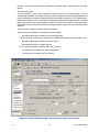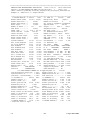
1
GEAR RATING SUITE By AGMA FOR EXTERNAL INVOLUTE SPUR AND HELICAL GEARS ISO 6336:1996 and ANSI/AGMA 2001-- C95 USER MANUAL Version 2.2 E August 2006 American Gear Manufacturers Association All Rights Reserved American Gear Manufacturers Association (AGMA) Software License SINGLE USER PRODUCT This is a legal agreement between you, the end user, and American Gear Manufacturers Association, a Virginia, U.S.A. Corporation. BY OPENING THE SEALED SOFTWARE PACKAGES, AND/OR USING THE SOFTWARE YOU ARE AGREEING TO BE BOUND BY THE TERMS OF THIS AGREEMENT. IF YOU DO NOT AGREE TO THE TERMS OF THIS AGREEMENT, PROMPTLY RETURN THE UNOPENED DISC PACKAGE AND ACCOMPANYING ITEMS TO AGMA FOR A REFUND. 1. GRANT OF LICENSE AGMA grants you the right to use one copy of the enclosed AGMA software program (the “SOFTWARE”) on a single computer when it is loaded into temporary memory (i.e., RAM) or installed into permanent memory (e.g., hard disk, CD ROM, or other storage device) of that computer. 2. COPYRIGHT The SOFTWARE is owned by AGMA and is protected by United States copyright laws and international treaty provisions and all other applicable national laws. Therefore, you must treat the SOFTWARE like any other copyrighted material (e.g., a book or musical recording) except that you may either (a) make one copy of the SOFTWARE solely for backup or archival purposes, or (b) transfer the SOFTWARE to a single hard disk provided you keep the original solely for backup or archival purposes. You may not copy the material accompanying the SOFTWARE. 3. OTHER RESTRICTIONS You may not rent or lease the SOFTWARE, but you may transfer the SOFTWARE and accompanying materials on a permanent basis provided you retain no copies and the recipient agrees to the terms of the Agreement. You may not reverse engineer, decompile or disassemble the SOFTWARE. If the SOFTWARE is an update or has been updated, any transfer must include the most recent update and all prior versions. 4. U.S. GOVERNMENT RESTRICTED RIGHTS The SOFTWARE and documentation are provided with RESTRICTED RIGHTS. Use, duplication, or disclosure by the Government is subject to restrictions as set forth in subparagraph (c)(1)(ii) of The Rights in Technical Data and Computer Software clause at DFARS 252.227--7013 or subparagraph (c)(1) and (2) of the Commercial Computer Software ---- Restricted Rights at 48 CFR 52.227--19, as applicable. Manufacturer is American Gear Manufacturers Association/500 Montgomery Street, Suite 350/Alexandria, Virginia 22314--1560. E August 2003 AGMA ii V10 COPYRIGHT E Copyright August 2003 by American Gear Manufacturers Association (AGMA). All rights reserved unless the licensee has been given approval in writing by AGMA. This manual is protected by federal copyright law. No part of this manual may be copied, transmitted, stored in retrieval system in any form or by any means, electronic, mechanical, manual, or otherwise, or disclosed to others. DISCLAIMER This software should not be used as the sole tool in the design evaluation process. If used, it should only be used in conjunction with other design and selection procedures. Use this product at your own risk. THIS SOFTWARE IS OFFERED AS--IS WITHOUT ANY WARRANTY, EXPLICIT OR IMPLIED INCLUDING WITHOUT LIMITATION ANY WARRANTY OF MERCHANTABILITY OR FITNESS FOR A PARTICULAR PURPOSE. IN NO EVENT, SHALL AGMA OR INDIVIDUALS INVOLVED IN THE SOFTWARE DEVELOPMENT BE HELD LIABLE FOR INCIDENTAL OR CONSEQUENTIAL DAMAGES THAT RESULT FROM USING THIS SOFTWARE. TRADEMARKS -- MicrosoftR is a registered trademark and WindowsR is a trademark of Microsoft Corporation. -- AcrobatR is a registered trademark of the Adobe Corporation. V10 iii E August 2003 AGMA Contents 1 Introduction . . . . . . . . . . . . . . . . . . . . . . . . . . . . . . . . . . . . . . . . . . . . . . . . . . . . . . . . . . . . . 1--1 1.1 1.2 1.3 1.4 1.5 1.6 1.7 2 3.2 3.3 3.4 3.5 4.7 4.8 4.9 4.10 4.11 4.12 4.13 Menu Bar – Input Window . . . . . . . . . . . . . . . . . . . . . . . . . . . . . . . . . . . . . . . . . . . . . . . . . . . 3.1.1 File . . . . . . . . . . . . . . . . . . . . . . . . . . . . . . . . . . . . . . . . . . . . . . . . . . . . . . . . . . . . . . . . 3.1.2 Data Set . . . . . . . . . . . . . . . . . . . . . . . . . . . . . . . . . . . . . . . . . . . . . . . . . . . . . . . . . . . 3.1.3 Display Units . . . . . . . . . . . . . . . . . . . . . . . . . . . . . . . . . . . . . . . . . . . . . . . . . . . . . . . 3.1.4 Run Data . . . . . . . . . . . . . . . . . . . . . . . . . . . . . . . . . . . . . . . . . . . . . . . . . . . . . . . . . . 3.1.5 Help . . . . . . . . . . . . . . . . . . . . . . . . . . . . . . . . . . . . . . . . . . . . . . . . . . . . . . . . . . . . . . . Menu Bar – Output Window . . . . . . . . . . . . . . . . . . . . . . . . . . . . . . . . . . . . . . . . . . . . . . . . . . 3.2.1 File . . . . . . . . . . . . . . . . . . . . . . . . . . . . . . . . . . . . . . . . . . . . . . . . . . . . . . . . . . . . . . . . 3.2.2 Window . . . . . . . . . . . . . . . . . . . . . . . . . . . . . . . . . . . . . . . . . . . . . . . . . . . . . . . . . . . . Tool Bar . . . . . . . . . . . . . . . . . . . . . . . . . . . . . . . . . . . . . . . . . . . . . . . . . . . . . . . . . . . . . . . . . . . The Navigation Pane . . . . . . . . . . . . . . . . . . . . . . . . . . . . . . . . . . . . . . . . . . . . . . . . . . . . . . . Input Window and Output Window . . . . . . . . . . . . . . . . . . . . . . . . . . . . . . . . . . . . . . . . . . . . 3--1 3--2 3--2 3--3 3--3 3--3 3--3 3--3 3--4 3--4 3--4 3--5 General Data . . . . . . . . . . . . . . . . . . . . . . . . . . . . . . . . . . . . . . . . . . . . . . . . . . . . . . . . . . . . . . 4--2 Gear Set Geometry . . . . . . . . . . . . . . . . . . . . . . . . . . . . . . . . . . . . . . . . . . . . . . . . . . . . . . . . . 4--3 Tolerance Worksheet . . . . . . . . . . . . . . . . . . . . . . . . . . . . . . . . . . . . . . . . . . . . . . . . . . . . . . . 4--6 Tooth Thickness . . . . . . . . . . . . . . . . . . . . . . . . . . . . . . . . . . . . . . . . . . . . . . . . . . . . . . . . . . . . 4--7 Tool Data . . . . . . . . . . . . . . . . . . . . . . . . . . . . . . . . . . . . . . . . . . . . . . . . . . . . . . . . . . . . . . . . . 4--13 Geometry Checking . . . . . . . . . . . . . . . . . . . . . . . . . . . . . . . . . . . . . . . . . . . . . . . . . . . . . . . 4--15 4.6.1 Edit Check Limits . . . . . . . . . . . . . . . . . . . . . . . . . . . . . . . . . . . . . . . . . . . . . . . . . . 4--15 4.6.2 Geometry Checking Routine . . . . . . . . . . . . . . . . . . . . . . . . . . . . . . . . . . . . . . . . . 4--15 4.6.3 Summary Produced by Geometry Checking Routine . . . . . . . . . . . . . . . . . . . . 4--16 Configuration and Application Data . . . . . . . . . . . . . . . . . . . . . . . . . . . . . . . . . . . . . . . . . . 4--17 ISO 6336 Materials and Configuration . . . . . . . . . . . . . . . . . . . . . . . . . . . . . . . . . . . . . . . . 4--19 ISO 6336 Factors . . . . . . . . . . . . . . . . . . . . . . . . . . . . . . . . . . . . . . . . . . . . . . . . . . . . . . . . . 4--22 AGMA 2001 Materials and Application . . . . . . . . . . . . . . . . . . . . . . . . . . . . . . . . . . . . . . . 4--24 AGMA 2001 Factors . . . . . . . . . . . . . . . . . . . . . . . . . . . . . . . . . . . . . . . . . . . . . . . . . . . . . . . 4--26 Review and Edit Input Data . . . . . . . . . . . . . . . . . . . . . . . . . . . . . . . . . . . . . . . . . . . . . . . . . 4--28 Calculate Gear Ratings . . . . . . . . . . . . . . . . . . . . . . . . . . . . . . . . . . . . . . . . . . . . . . . . . . . . 4--28 Output Window . . . . . . . . . . . . . . . . . . . . . . . . . . . . . . . . . . . . . . . . . . . . . . . . . . . . . . . . . . 5--1 5.1 5.2 5.3 6 2--1 2--1 2--1 2--1 2--1 2--2 Data Input Windows . . . . . . . . . . . . . . . . . . . . . . . . . . . . . . . . . . . . . . . . . . . . . . . . . . . . . . 4--1 4.1 4.2 4.3 4.4 4.5 4.6 5 Software on Compact Disc . . . . . . . . . . . . . . . . . . . . . . . . . . . . . . . . . . . . . . . . . . . . . . . . . . Computer System Requirements and Installation . . . . . . . . . . . . . . . . . . . . . . . . . . . . . . . 2.2.1 System Requirements . . . . . . . . . . . . . . . . . . . . . . . . . . . . . . . . . . . . . . . . . . . . . . . 2.2.2 Disc File Information . . . . . . . . . . . . . . . . . . . . . . . . . . . . . . . . . . . . . . . . . . . . . . . . . 2.2.3 Installation . . . . . . . . . . . . . . . . . . . . . . . . . . . . . . . . . . . . . . . . . . . . . . . . . . . . . . . . . 2.2.4 Uninstall . . . . . . . . . . . . . . . . . . . . . . . . . . . . . . . . . . . . . . . . . . . . . . . . . . . . . . . . . . . Gear Rating Suite Main Input Window . . . . . . . . . . . . . . . . . . . . . . . . . . . . . . . . . . . . . 3--1 3.1 4 1--1 1--2 1--2 1--2 1--3 1--3 1--4 Getting Started . . . . . . . . . . . . . . . . . . . . . . . . . . . . . . . . . . . . . . . . . . . . . . . . . . . . . . . . . . 2--1 2.1 2.2 3 About This Software . . . . . . . . . . . . . . . . . . . . . . . . . . . . . . . . . . . . . . . . . . . . . . . . . . . . . . . . Limitations . . . . . . . . . . . . . . . . . . . . . . . . . . . . . . . . . . . . . . . . . . . . . . . . . . . . . . . . . . . . . . . . . Organization of This User Manual . . . . . . . . . . . . . . . . . . . . . . . . . . . . . . . . . . . . . . . . . . . . Application Notes . . . . . . . . . . . . . . . . . . . . . . . . . . . . . . . . . . . . . . . . . . . . . . . . . . . . . . . . . . . Overview . . . . . . . . . . . . . . . . . . . . . . . . . . . . . . . . . . . . . . . . . . . . . . . . . . . . . . . . . . . . . . . . . . Starting . . . . . . . . . . . . . . . . . . . . . . . . . . . . . . . . . . . . . . . . . . . . . . . . . . . . . . . . . . . . . . . . . . . References . . . . . . . . . . . . . . . . . . . . . . . . . . . . . . . . . . . . . . . . . . . . . . . . . . . . . . . . . . . . . . . . Print Output . . . . . . . . . . . . . . . . . . . . . . . . . . . . . . . . . . . . . . . . . . . . . . . . . . . . . . . . . . . . . . . 5--2 Displaying and Printing Output Files From Disk . . . . . . . . . . . . . . . . . . . . . . . . . . . . . . . . . 5--2 Close Output Window . . . . . . . . . . . . . . . . . . . . . . . . . . . . . . . . . . . . . . . . . . . . . . . . . . . . . . . 5--2 ISO 6336 Error Messages . . . . . . . . . . . . . . . . . . . . . . . . . . . . . . . . . . . . . . . . . . . . . . . . 6--1 6.1 6.2 6.3 6.4 Data Error Messages . . . . . . . . . . . . . . . . . . . . . . . . . . . . . . . . . . . . . . . . . . . . . . . . . . . . . . . Durability Error Messages . . . . . . . . . . . . . . . . . . . . . . . . . . . . . . . . . . . . . . . . . . . . . . . . . . . Durability Factors Error Messages . . . . . . . . . . . . . . . . . . . . . . . . . . . . . . . . . . . . . . . . . . . . Gear Geometry Error Messages . . . . . . . . . . . . . . . . . . . . . . . . . . . . . . . . . . . . . . . . . . . . . . E August 2003 AGMA iv 6--1 6--2 6--2 6--2 V10 6.5 6.6 6.7 6.8 6.9 6.10 7 6--6 6--6 6--8 6--8 6--9 6--9 AGMA 2001 Error Messages . . . . . . . . . . . . . . . . . . . . . . . . . . . . . . . . . . . . . . . . . . . . . . 7--1 7.1 7.2 7.3 7.4 7.5 7.6 7.7 7.8 7.9 7.10 7.11 8 Hardness Error Messages . . . . . . . . . . . . . . . . . . . . . . . . . . . . . . . . . . . . . . . . . . . . . . . . . . . Load Distribution Error Messages . . . . . . . . . . . . . . . . . . . . . . . . . . . . . . . . . . . . . . . . . . . . . Material Properties Error Messages . . . . . . . . . . . . . . . . . . . . . . . . . . . . . . . . . . . . . . . . . . . Strength Error Messages . . . . . . . . . . . . . . . . . . . . . . . . . . . . . . . . . . . . . . . . . . . . . . . . . . . . Strength Factors Error Messages . . . . . . . . . . . . . . . . . . . . . . . . . . . . . . . . . . . . . . . . . . . . . Velocity Error Messages . . . . . . . . . . . . . . . . . . . . . . . . . . . . . . . . . . . . . . . . . . . . . . . . . . . . . Dynamic Factor Error Messages . . . . . . . . . . . . . . . . . . . . . . . . . . . . . . . . . . . . . . . . . . . . . Effective Case Error Messages . . . . . . . . . . . . . . . . . . . . . . . . . . . . . . . . . . . . . . . . . . . . . . . Gear Geometry Error Messages . . . . . . . . . . . . . . . . . . . . . . . . . . . . . . . . . . . . . . . . . . . . . . 908 Gear Geometry Factor I Error Messages . . . . . . . . . . . . . . . . . . . . . . . . . . . . . . . . . . 908 Gear Geometry Factor J Error Messages . . . . . . . . . . . . . . . . . . . . . . . . . . . . . . . . . . General Geometry Error Messages . . . . . . . . . . . . . . . . . . . . . . . . . . . . . . . . . . . . . . . . . . . Hardness Conversion Error Messages . . . . . . . . . . . . . . . . . . . . . . . . . . . . . . . . . . . . . . . . Material Allowable Error Messages (all hardnesses in BHN) . . . . . . . . . . . . . . . . . . . . . . Mesh Factor Error Messages . . . . . . . . . . . . . . . . . . . . . . . . . . . . . . . . . . . . . . . . . . . . . . . . Rating Routine Error Messages . . . . . . . . . . . . . . . . . . . . . . . . . . . . . . . . . . . . . . . . . . . . . . Strength and Stress Cycle Factor Error Messages . . . . . . . . . . . . . . . . . . . . . . . . . . . . . . 7--1 7--2 7--3 7--4 7--4 7--4 7--5 7--6 7--8 7--8 7--9 Trouble Shooting . . . . . . . . . . . . . . . . . . . . . . . . . . . . . . . . . . . . . . . . . . . . . . . . . . . . . . . . 8--1 8.1 8.2 No output due to FATAL ERRORS . . . . . . . . . . . . . . . . . . . . . . . . . . . . . . . . . . . . . . . . . . . . 8--1 Procedure for Installing OLEAUT32.DLL File . . . . . . . . . . . . . . . . . . . . . . . . . . . . . . . . . . . 8--1 Annexes A Sample Output File -- 6336, Short Form Single Reduction Gear Set . . . . . . . . . . A--1 B Sample Output File -- 2001, Short Form Single Reduction Gear Set . . . . . . . . . . B--1 C Sample Output File -- 6336, Long Form Single Reduction Gear Set . . . . . . . . . . C--1 D Sample Output File -- 2001, Long Form Single Reduction Gear Set . . . . . . . . . . D--1 E Method for Determining the Start of Involute . . . . . . . . . . . . . . . . . . . . . . . . . . . . . . . E--1 V10 v E August 2003 AGMA (This page is intentionally left blank.) E August 2003 AGMA vi V10 1 Introduction This Gear Rating Suite calculates load capacities of external involute spur and helical gears according to ISO 6336 and/or AGMA 2001 Standards. The program attempts to interpret these standards faithfully without imposing design rules; thereby, a wide range of gears can be analyzed. The program also incorporates material from the following standards (See section 1.7, References, for full designation and titles): -- AGMA 908 Geometry Factors -- AGMA 2000 Tolerances -- AGMA 2002 Tooth thickness -- AGMA 2015 Accuracy, tangential -- ISO 1328--1 Accuracy, tangential -- ISO 1328--2 Accuracy, radial -- ASTM E140 Hardness Conversion The user is required to enter gear set and cutting tool geometry, material data, loads, and may enter some special factors required by the standards. The gear geometry may be entered or displayed in many different ways, for example if the normal module is entered the transverse circular pitch can be displayed. The program will calculate gear tooth ratings, influence factors and safety factors. Tedious manual computations in the ISO 6336 and AGMA 2001 Standards rating procedures are avoided. Upon completion of the calculations, results are displayed and may be printed. The standard package consists of a CD, which includes the files listed in section 2.2.2. If the package is not complete or for further information, contact AGMA for details: American Gear Manufacturers Association 500 Montgomery Street, Suite 350 Alexandria, Virginia, 22314--1560 Phone: (703) 684--0211 FAX: (703) 684--0242 Internet: [email protected] 1.1 About This Software The Gear Rating Suite by AGMA offers the following features: V10 -- Both ISO 6336 and AGMA 2001 Standards may be used to calculate rating factors. -- Safety factors may be calculated based on the input power, or for AGMA 2001, the allowable power may be calculated from the factors entered. -- User friendly I/O provides an intuitive user interface, with drop--down boxes, look--up tables, and graphical guides used liberally to assist in data entry. -- Dual input units allow the user to switch between SI and inch input units at any time. -- Flexible data entry concept allows the user to enter data in an accustomed format; for example, the user can choose from ten different methods in specifying gear tooth thickness. -- Tolerance worksheets allow the user to calculate tooth tolerances from quality number, convert quality numbers between AGMA and ISO, and to display tolerances for adjacent grades. -- Hardness conversion routine allows any of 8 different hardness scales to be used for data entry. Conversion between different scales may be done with a click on the new scale. The conversions are for steel only and are approximate. -- Multiple data sets within a single file enable the user to rate multiple gear sets in a single program run. New data sets may be easily created or existing sets may be copied or edited from within the input window. -- User may set default limits for the input data checking done by the geometry checker. -- Geometry Checker is provided for checking input data to be within an allowable range. The geometry checker can help identify data entry errors and unusual gear designs. It is always run before rating calculations are done (and may also be run from the Tool Data window). 1--1 E August 2003 AGMA -- Start of Involute Diameter (SOI) is calculated for gears cut with hobs or rack type cutters as part of geometry checking. An accurate method is used that applies to all hobs with or without protuberance and with circular tip radius. See Annex E for a description of how SOI is calculated. -- Error and warning messages are provided both within the input routine and within the rating routines to help identify problems. -- On--line help is incorporated into the program. -- Long and short form outputs are provided. The long form shows the calculated values, variable names in ISO6336 only, and the calculation method for rating factors. The short form prints the values of the factors and the calculation method in a compact format. In both cases, error messages and notes are printed before the gear rating output. 1.2 Limitations External gears only: geometry and rating of internal gears can not be checked with this program. For ISO 6336 Rating: The program and this manual were developed for ISO 6336 Standards as listed in References (section 1.7). They are limited to the parameters of ISO 6336 and are not valid outside these limits. Revised software will be required for future versions of ISO 6336 rating standards. The Gear Rating Suite and information in this document are subject to change without notice. For AGMA 2001 Rating: The program and this manual were developed for AGMA Standards as listed in References (section 1.7). They are limited to the parameters of AGMA 908 & 2001 Standards and are not valid outside these limits. Revised software will be required for future versions of the standards. The Gear Rating Suite and information in this document are subject to change without notice. In order to allow the widest range of designs to be analyzed, few limits are set during input. Although there are many input checks and warning messages, the program does not check to see if all of your geometry is correct, can be manufactured or assembled. You must independently verify that the gear geometry, which you choose, is valid for real gears. The programs do not check to see if all of your input values are within the scope of ISO 6336 or AGMA 2001 Standards. Please refer to the appropriate clauses of these and related standards for specific limits. The program is not designed to support multiple accesses by computers on a network. 1.3 Organization of this User Manual Chapter 1 Overview of this software Chapter 2 System requirements to use this software and the software setup procedures Chapter 3 Main input window Chapter 4 Data Input: -- Data common to both ISO 6336 and AGMA 2001 rating standards -- Data for ISO 6336 Ratings -- Data for AGMA 2001 Ratings Chapter 5 Data Output Chapter 6 ISO 6336 Error Messages, with descriptions Chapter 7 AGMA 2001 Error Messages, with descriptions Chapter 8 Trouble Shooting, tips to locate and identify problems 1.4 Application Notes This program is not meant to replace knowledge of rating procedures. The user must be familiar with the rating procedures and other related standards. This knowledge is needed to select appropriate input factors for the rating procedures. The output data of this Gear Rating Suite are only valid if the input data are valid and engineering decisions are correct. E August 2003 AGMA 1--2 V10 In diversified gear applications, each case may require different processes for gear quality, material specifications and manufacturing. It is impossible to give input variable default values suitable for all applications. The user may store a default display setup to be used for new data sets. In addition, you may wish to store default values specific to your applications in an input file. 1.5 Overview These programs will permit the user to rate gear sets either to the ISO 6336 Standard or the AGMA 2001 Standard or both. If rating according to both standards, all data must be entered. If you want to rate to only one standard, the program only needs geometry data (needed for either standard) and the Materials and Factors data for the standard to be used. You may enter data in SI units or US Customary units, and you may change units at any time. When input units are changed, the program will display all data in the new units. You should be aware that although the data is rounded for display, it is stored and sent to the rating routines in double precision. The amount of rounding is dependent on the magnitude of the number. You can specify the units for the output or get the output in both units. It is recommended that after a typical data set has been entered, and while it is still displayed, the “Save Setup” choice on the File menu be used. This will simplify future data entry by setting all display defaults to your preferences. The input program will check the input for geometry errors and display error messages if the data does not provide correct geometry. A typical session consists of the following steps: -- Start the program -- Enter and edit data -- Calculate ratings -- Display calculated results -- Print output There are three levels of data checking: -- As you leave each data entry window, a cursory check will be done by the input routine for that window. -- A geometry check is done on the data before the rating programs are called, and may also be invoked from the tool window. When invoked from the tool window, a summary window will be displayed with some calculated values that are otherwise not visible. The limits used for checking may be set by the user (from the menu item File Edit Check Limits). -- Each rating routine has its own error checks. There are three classes of error messages in the ISO 6336 program, and four in the AGMA 2001 program: -- FATAL ERROR is an error which will prevent the program from running successfully. -- WARNING (STANDARD VIOLATED) The geometry of this set is outside the scope of the applicable AGMA standards (AGMA 2001 or 908). Read the applicable section of the standard and then revise your input to conform to the standard. Because the requirements of the standard have not been met, the results shall not be used either as the basis for design or for comparing the capacity of gears. -- WARNING is used to indicate that the calculated results may not be valid, and should be checked carefully. -- NOTE is a message to the user to indicate either an approximated value is used for a rating factor, or the program has set a value for a rating factor, which may not have been the user’s intention. Verify the output for validity. 1.6 Starting The program will display a window containing copyright and version information and a statement regarding acceptance of the agreement. Click on the button labeled ‘I Agree to the Above’ if you agree with the statement and want to proceed, or click on the button labeled ‘Cancel’ to exit the program. V10 1--3 E August 2003 AGMA 1.7 References 1. AGMA 908--B89 Geometry Factors for Determining the Pitting Resistance and Bending Strength of Spur, Helical and Herringbone Gear Teeth 2. AGMA 913--A98 Method of Specifying the Geometry of Spur and Helical Gears 3. AGMA 918--A93 A Summary of Numerical Examples Demonstrating the Procedures for Calculating Geometry Factors for Spur and Helical Gears 4. AGMA 2000--A88 Gear Classification And Inspection Handbook -- Tolerances And Measuring Methods For Unassembled Spur And Helical Gears (Including Metric Equivalents). 5. ANSI/AGMA 2001--C95 Fundamental Rating Factors and Calculation Methods for Involute Spur and Helical Gear Teeth 6. ANSI/AGMA 2002--B88 Tooth thickness Specification and Measurement 7. ASTM E 140--97 Standard Hardness Conversion Tables for Metals 8. ISO 53:1998 Cylindrical gears for general and heavy engineering ---- Standard basic rack tooth profile 9. ISO 1328--1:1995 Cylindrical gears ---- ISO system of accuracy ---- Part 1: Definitions and allowable values of deviations relevant to corresponding flanks of gear teeth 10. ISO 6336--1:1996 Calculation of load capacity of spur and helical gears ---- Part 1: Basic principles, introduction and general influence factors 11. ISO 6336--2:1996 Calculation of load capacity of spur and helical gears ---- Part 2: Calculation of surface durability (pitting) 12. ISO 6336--3:1996 Calculation of load capacity of spur and helical gears ---- Part 3: Calculation of tooth bending strength 13. ISO 6336--5:1996 Calculation of load capacity of spur and helical gears ---- Part 5: Strength and quality of materials 14. Keiper, Richard D. Measurement Error Induced by Measuring over Pins Instead of Balls, Gear Technology, January 1996. 15. McVittie, Donald R. Describing Nonstandard Gears – an Alternative to the Rack Shift Coefficient, AGMA Fall Technical Meeting Paper 86 FTM 1, 1986 16. ANSI/AGMA 2015--1--A01, Accuracy Classification System -- Tangential Measurements for Cylindrical Gears 17. AGMA 915--1--A02, Inspection Practices -- Part 1: Cylindrical Gears -- Tangential Measurements E August 2003 AGMA 1--4 V10 2 Getting Started 2.1 Software on Compact Disc The programs on the compact disk (CD) include the SETUP software to install the input program, help file, and rating programs (AGMA 6336 Rating Program and 2001 Rating Program). After installation, the disc should be stored so it can be used to reinstall the program in case of a computer disk drive change or failure, or the program needs to be moved to a different computer. This software is designed to run on personal computers. For the purpose of this manual, the hard drive and CD drive are designated as the following: C: is the hard drive D: is the CD drive If the user’s drive designations are different than those stated above, use the appropriate drive designations. 2.2 Computer System Requirements and Installation 2.2.1 System Requirements Operating system: -- The software has been tested on Microsoft Windows 95, 98, NT 4.0, Millennium (Me), 2000 and XP Software: -- Microsoft Internet Explorer 4.0 or later version (for displaying on--line help file) -- Acrobat Reader 3.0 or later version (Acrobat Reader 5.0 setup file is included on the CD) Hardware: -- CD--ROM drive -- Hard disk drive with at least 25 MB of free disk space -- Display with a minimum resolution of 800x600 -- Printer (optional) 2.2.2 Disc File Information The Gear Rating Suite package (CD) contains the following: -- Gear Rating Suite setup file -- Readme.txt – contains installation instruction and last minute software information -- ISO 6336, AGMA 2001 and related standards (PDF, full version only) -- User manual (PDF) -- List of AGMA publications (PDF) -- Sample data file (included in the Gear Rating Suite setup file) -- Acrobat Reader 5.0 setup file If the package is not complete on the CD received, or for further information, contact AGMA. 2.2.3 Installation Before installing the program, it is recommended that you close all other running applications. If you have previously installed this program, it is recommended that you uninstall it before reinstallation. You must have administrator privileges to install this on your computer if it uses Windows NT, XP, or later network type operating system. V10 2--1 E August 2003 AGMA Install the Gear Rating Suite by inserting the distributed CD into the CD--ROM drive, the setup menu should display automatically. Click on Install Gear Rating Suite to initiate program installation. Follow the instructions to complete the installation procedure. See Trouble Shooting (Section 5 of ReadMe.txt), if the setup menu did not appear after inserting the CD. (1) If the setup program gives an error message stating that a .DLL or .OCX file is in use, it is because another application is using a file that the setup program needs. Quit the setup program and quit all other applications, then restart the setup program. (2) When the setup program prompts you for the name of a directory to install the program into, you may accept the default name (Agmarate) or enter a new one. SETUP will install all program files to this subdirectory and will install files required by Windows in the Windows system directory. (3) When the installation is complete, SETUP will create a program group and icon for the program on the Windows Start Menu. To start the program, double--click the icon. NOTE: During setup, a message box may appear stating “Setup cannot continue because some system files are out of date on your system...” This message indicates that the version of the file, OLEALT32.DLL, in your system is older than the one required by this program. For Windows 98 and earlier versions, click on OK in the message box to continue the setup procedures. For Windows 2000 and Me, refer to procedure outlined in Section 8.2, Procedure for Installing OLEAUT32.DLL File, to correct this problem. 2.2.4 Uninstall If you want to transfer the program to another computer or to erase it from the computer, use Windows Uninstall to remove the program (found in start-->settings-->control panel--> add/remove programs). Uninstall will not remove input or output data files created by the program. You will need to manually delete these files if they are no longer needed. If reinstalling the program, it must be installed from the CD initially used. E August 2003 AGMA 2--2 V10 3 Gear Rating Suite Main Input Window The main window has three main sections: -- The menu bar and the tool bar are across the top. Note that the menu bar changes depending on whether input or output is being displayed. -- The Navigation pane is on the left. -- The rest of the area is an input or output window. Figure 3--1 Gear Rating Suite Main Window 3.1 Menu Bar – Input Window Figure 3--2 Menu Bar -- Input Window The Input Window Menu Bar is activated when the input window is displayed. Some of the menu functions are duplicated in the tool bar to perform the menu function more efficiently. The menu bar is used to tell the program what you, as the user, would like it to do. There are five major headings: V10 -- File contains commands for file handling. -- Data Set has options for adding, copying, or deleting data sets within the current file. -- Display Units allows the user to select the units for entry and display. -- Run Data executes the calculations for the ratings requested and displays results. -- Help allows access to on--line help, user manual, and displays version number of this software. 3--1 E August 2003 AGMA Each menu item will activate and deactivate depending upon the state of the program and the actions of the user. For example, Data Set will only be available if data set(s) are loaded. The ‘Run’ menu remains inactive until a file is opened or a new set of data is entered and saved. NOTE: If the whole window as shown in Figure 3--1 does not appear on your computer, then it will be necessary to exit and click Windows ‘START’ and select ‘SETTINGS’, ‘Control Panel’, ‘Display’, ‘Settings’ to increase window area. This software requires a minimum desktop area of 800 x 600 pixels to display the full data input windows. 3.1.1 File -- New (Ctrl--N): Creates a new data file. Selecting this option will close the current data file. The “setup” that was saved with the “save setup” command will be used as the default for the new data file. -- Open (Ctrl--O): Displays a dialog box so that you may select a data file to open. The program will automatically display the first data set in the file you select. If the file contains more than one data set, you may then select the data set you wish to edit. NOTE: If you have input files from the old ISO 6336 Version 1.0 or 1.01 program by AGMA, this program can read them and store them in the new file format used by this program. When you open one of your old files, you will be asked for a new file name to store the converted data. If your old file used the extension .txt, then the simplest thing is to just use the new default extension of .dat. The data can be used to run the ISO 6336 program without entering additional data. However, you must enter additional data before calculating the AGMA 2001 rating. -- Save (Ctrl--S): Saves the current data by overwriting the existing file. If there is no current file, the “Save As” window will be displayed requesting a file name. -- Save As: Selecting this option saves the current data to a location specified by the user. -- Recall Setup: Recalls the last setup that was stored, except for the materials window and other data -- Save Setup: Saves the current setup, including the materials data and some rating specific factors. The display settings and data will be used for all new data sets. It is highly recommended that you use this function after entering a “typical” data set, while the data set is displayed. -- Edit Check Limits: Opens a window for editing the limits used by the geometry checker. See 4.6 for further information. -- List of the four most recently accessed data files, with full path. A single click on any file in the list will open that data file. -- View text file: Allows the user to display any text file. The default file extension is *.txt. To return to the input window, use the “Close Output Window” icon. -- Exit: To quit the program. 3.1.2 Data Set A single data file may contain multiple data sets. However, the program can only display one data set at a time. -- Add: Add a new (empty) data set to the end of an existing file. The new data set becomes the current data set. -- Copy: Copy the current data set and append it to the end of the current data file. The new data set (at the end of the file) becomes the current data set. -- Delete: Delete the current data set from the stored data file. The data set following the deleted data set becomes the current data set. If the last data set in a multiple data set file is deleted, the data set before the deleted one becomes the current data set. When this option is selected, a box appears to ask the user if they really want to delete the current data set. If there is only one data set in the file, the entire data file will be deleted (as is noted in the warning message prior to completing the function). NOTE: When entering data for a new data file, the Data Set menu items Add, Copy, and Delete are de--activated until the data set is saved. To delete a new data set that has not been saved, use File|New menu item if you want to remain in the program, or use File|Exit menu item to exit program. E August 2003 AGMA 3--2 V10 3.1.3 Display Units You may click on either of these choices at any time to display the input data in the units indicated. -- SI: Displays input data in SI units. (i.e. millimeters, Newtons, kW). -- Inch: Displays input data in US Customary units (i.e. inches, pounds--force, and horsepower). 3.1.4 Run Data The ratings that are run depend on the selection made in the “General Data” window of the data set. -- Current (F5): Run current data, i.e., the data that is currently displayed on the input windows. -- All: Run all data sets in current data file. -- Selected: Run only specified data sets from the current file. 3.1.5 Help This item will open the on--line help files for the program. The options are: -- Contents: Display the contents of the HELP file. -- Search: Search for key words. -- View User Manual: Allows the user to view the User Manual with Acrobat Reader. -- Technical Support: Provides procedure for reporting a problem. -- About: The software version number and copyright date. 3.2 Menu Bar – Outupt Window Figure 3--3 Menu Bar -- Output Window The Output Window Menu Bar is activated when the output window is displayed. Some of the menu functions are duplicated in the tool bar to perform the menu functions more efficiently. The menu bar is used to tell the program what you, as the user, would like it to do. 3.2.1 File ---- ------ Find String (Ctrl--F): Searches for a string in the displayed file. The search starts from the point where the last item was found, or at the top of the file if this is the first search. Find Next (F3): Repeats the search for a string in the displayed file. The search starts from the point where the last item was found. Save As: Used to save the currently displayed file to a different file name. Note: The output files are erased with each new run of the rating programs. If you wish to save an output file, you must use this menu item to save it with a new name. Print out6336.txt: (Visible only when applicable) Sends the output file to the default windows printer. Print out2001.txt: (Visible only when applicable) Sends the output file to the default windows printer. Print All: Sends all loaded output or text files to the default windows printer. Select/Setup Printer: Allows you to select a printer. Close Output Window: Will unload all displayed files and return to the input window. 3.2.2 Window A list of all loaded text or output files. If there is more than one file loaded, you may click on the file you wish to have displayed. 3.3 Tool Bar Certain input and output window menu items that are commonly used have been represented as toolbar icons. Clicking on any one of these is a shortcut to execute the function of the associated menu item. These icons will be enabled and disabled as the menu items they are associated with are activated and deactivated. The function each icon represents will be displayed if the mouse pointer is left on the icon for a few seconds. V10 3--3 E August 2003 AGMA There are twelve tools: New File SI units Open File Inch Units Save File Run Current Data Set Add New Data Set Print Output Window (current file) Copy Current Data Set Close Output Window Delete Current Data Set Display Help Contents NOTE: The Print and Close Output Window icons are only active in the output window. 3.4 The Navigation Pane The navigation pane enables the user to: -- Select any data set from a data file with multiple data sets. -- Add, copy, save or delete a data set. -- Select an input window. -- Select rating output for display. The components of the navigation pane are: -- Data File Indicator is located at the top of the navigation pane. It displays the current data file name. -- Data Set Selector is the drop--down box below the Data File Indicator. It shows the current data set. Click on the drop--down box to go to a different data set. (The program will unload the current data set and load the selected new data set.) -- Add button is used to add a new data set to the end of current data file. This button performs the same function as the Data Set | Add menu item. NOTE: If a large number of data sets are added, be aware that the run time for the computer will increase far longer than the number of data sets times the time to run one set. -- Copy button is used to duplicate the current data set and append it to the end of the current data file. This button performs the same function as the Data Set | Copy menu item. -- Save button is used to store the current data set to the current data file. This button performs the same function as the File | Save menu item. -- Delete button is used to delete the current data set from the data file. This button performs the same the function as the Data Set | Delete menu item. -- Input Windows A list of the input windows, with the current input window highlighted. Depending on the gear rating standard selected, some of the windows will be deactivated. Click on the title of any active window to display it. The program disables the Input Windows box when the output window is displayed. You must close the output window to activate the Input Windows box again (use the “Close Output Window” icon). -- Output Window drop--down box allows the user to change the output file displayed. It performs the same function as the “Window” command. If the output window is closed after a rating has been run, this box may be used to again look at the results of the last rating. 3.5 Input Window and Output Window The Input Window occupies the same screen space as the Output Window (which is all of the space not occupied by the Menu Bar, Tool Bar, and the Navigation Pane). The input windows are used for entering input data. Only one input window can be displayed at any time. There are nine input windows for entering data. Some of the windows are common to ISO 6336 and AGMA 2001, and some are for one of the standards only. E August 2003 AGMA 3--4 V10 4 Data Input Windows The following are some considerations when entering data: -- All windows with no specific indication of either ISO 6336 or AGMA 2001 must have all of the requested data entered in order to run the program. They are: General Data Gear Set Geometry Tooth Thickness * Tool Data * Configuration & Application Data * -- Additional windows that require data for ISO 6336 ratings are: ISO 6336 Materials ISO 6336 Factors -- Additional windows that require data for AGMA 2001 ratings are: AGMA 2001 Materials AGMA 2001 Factors You may navigate between the windows either by clicking on the titles in the navigation pane or by clicking on the “<Back” and “Next>” buttons at the top of the window. The user may choose SI or inch measurement units to enter input data. The units may be changed at any time. When the units are changed, the previously entered data will be displayed in the new units. Be sure to enter data according to the measurement units indicated. The program checks for unacceptable inputs and, if present, will display a message before moving to the next window or starting calculations. WARNING: In order to allow the widest range of designs to be analyzed, limits are not set on input. The program does not fully check to see if the gear set can be manufactured or assembled. You must independently verify that the gear geometry, which you choose, is valid for real gears. For ISO ratings, please refer to ISO 1328--1:1995 and ISO 6336 standards. Please refer to ISO 6336--1, clause 1, for general guidance and the individual clauses of both ISO standards for specific limits. For AGMA 2001 ratings, please refer to AGMA 2001 and related Standards. Results for any gears not within those limitations are not valid. The program does not check for all limits, but will run and give a warning message(s) if those limits that are checked are not within the range specified in the respective standard. The symbols and abbreviations used in the standards are shown with the data entry explanations. ISO symbols are shown without brackets, and AGMA symbols are shown inside brackets [ ]. ________________ *Not enabled until the gear geometry has been entered. V10 4--1 E August 2003 AGMA 4.1 General Data When the program is first started, it is ready to accept new data. Figure 4--1 General Data Gear Set Title Standard Input Units Output Units Output Format Enter a descriptive title for this data set. Three (3) lines are provided with up to 80 characters per line. Select the Standard(s) to be used to rate the gear set. You can enter data with either SI or US Customary units. Select the data measurement units for the output. Select the output form format. See Annexes A through D for short and long form sample outputs. The date and time of file storage are read from the computer clock, so no input is required for these. Display extended precision checkbox: All data are stored in full precision, but are rounded for display. The number of digits displayed to the right of the place holder depends on the magnitude of the number being displayed, except for angles, axial pitch and tool addendum, which are always shown to 4 places. When inches are displayed, no more than 4 places will be shown, while in SI only 3 places are shown. The display changes at values of 30, 300, etc. Checking this box will display four additional digits. These extra digits may be useful in checking results against another calculation procedure. However, it is recommended that the checkbox be unchecked for normal data entry. The status of this checkbox is not saved and it cannot be set to be checked as a default. E August 2003 AGMA 4--2 V10 4.2 Gear Set Geometry Figure 4--2 Gear Set Geometry NOTE 1: Select the units (US Customary or SI) prior to entering data. NOTE 2: The high amount of flexibility in this program requires you to use care when changing such basic parameters as pressure angle, module (or diametral pitch), or helix angle. Due to the way data is stored, a change may have consequences that may be initially surprising. A set of very basic data is stored, and from that data the displayed data is generated. For example, the normal base tooth thickness is stored, so changes in pressure angle, module (or diametral pitch), helix angle, or number of teeth will affect all tooth thickness measurements except the normal base tooth thickness. Hob information is stored as an equivalent 10,000 tooth shaper with a fixed outside diameter and a helix angle to match the gear. Therefore, changing one of the basic parameters will alter the hob data. Older programs generally avoided this problem by only allowing one method of entering data. The highly flexible input routine should make data input and editing very easy, as long as the user is aware of these things. External Gear Set -- This version of the software does not rate internal gears. Select Gear Set Type: -- Spur -- Single Helical -- Double Helical Normal Reference Pressure Angle, n [Ôn] Enter normal pressure angle at reference diameter (decimal degrees). This is the same as the “normal generated pressure angle” and the “normal profile angle of the equivalent standard rack cutter”. V10 4--3 E August 2003 AGMA NOTE 3: Changes in pressure angle of an existing data set will usually require changes in other geometry to have a valid gear set. All entries in this window, the tolerance window, the tooth thickness window, and the tool window(s) should be checked. Select Method for specifying basic tooth size: -- Normal Module, mn (mm) -- Normal Diametral Pitch (1/in) [commonly referred to as DP, Pnd in AGMA 2001] -- Normal Circular Pitch (mm or in) -- Normal Circular Base Pitch, [pN] (mm or in) -- Transverse Module, mt (mm) -- Transverse Diametral Pitch, [Pd] (1/in) -- Transverse Circular Pitch (mm or in) Enter either a normal module or a pitch. Modules must be entered in units of millimeters and diametral pitch must be entered in units of 1/inch regardless of the type of input units selected. Circular Pitch must be entered in the currently selected input units. Transverse pitch may only be entered or displayed after the helix angle or axial pitch is entered. For transverse circular pitch, refer to ANSI/AGMA 2002--B88 clause 3.1.4, page 9. NOTE 4: Changes in the basic tooth size of an existing data set, will usually require changes in other geometry to have a valid gear set. However, when the basic tooth size is changed, if helix angle is displayed, the axial pitch will be recalculated to maintain that helix angle. All entries on this window, the tolerance window, the tooth thickness window, and the tool window(s) should be checked. The normal circular base pitch is stored. Select Method for specifying Helix Angle or Axial Pitch (Single or Double Helical gears only), []: -- Axial Pitch, [px] (mm or in) -- Helix Angle at standard diameter (generating helix angle), [] (decimal degrees) --- If the generating helix angle is entered prior to entering the module or pitch, then the transverse module or pitch may be entered. Helix Angle at base diameter, b [b] (decimal degrees) Helix Angle at given diameter (decimal degrees) This will allow you to enter or display the helix angle at any diameter. During initial data entry, if this option is selected you must enter the given diameter and the pinion number of teeth prior to entering the helix angle. NOTE 5: Changes in the helix angle of an existing data set will usually require changes in other geometry to have a valid gear set. All entries on this window, the tolerance window, the tooth thickness window, and the tool window(s) should be checked. The axial pitch is stored. Given Pinion Diameter, d1 [ D ] (mm or in) Enter the Given Pinion Diameter at which the helix angle is to be entered or displayed. Changing this number will not change the axial pitch, it will only change the displayed helix angle Select method for specifying Center Distance, a [C] -- Maximum and Minimum distance between gear centers -- Minimum distance between gear centers with unilateral tolerance to maximum (mm or in) -- Mean distance between gear centers and the bi--directional tolerance on this distance NOTE 6: If only the nominal center distance is known, specify the mean center distance and enter zero for the tolerance. NOTE 7: When a center distance range is specified, the mean center distance will be used for the ISO rating while the minimum center distance will be used for AGMA. E August 2003 AGMA 4--4 V10 Number of Teeth, z1, z2 [Np,NG] After the number of teeth is entered, the standard center distance will be displayed for reference. NOTE 8: Changes in the number of teeth of an existing data set, will usually require changes in other geometry to have a valid gear set. All entries on this window, the tolerance window, and the tooth thickness window should be checked. Maximum Tip Diameter, da max [ Do max] (mm or in) Enter tip (outside) diameter of pinion & gear (wheel) respectively. Select method for specifying Minimum Tip Diameter, da min [Do min] (mm or in) -- Minimum Tip Diameter -- Tip Diameter Unilateral Tolerance NOTE 9: The minimum tip diameter is only used in geometry checking, not in the rating procedures. Face Width, b [F] (mm or in) Enter face widths for pinion and gear (wheel) respectively. In the case of double helical gears, enter sum of both helices (not including gap width). If the face width exceeds 250 mm, a warning will be generated based on ANSI/AGMA 2001--C95. This will not prevent a rating from being obtained. Double Helical Gap (mm or in) Enter the gap width between helices of a double helical for pinion and gear (wheel) respectively. Select method for specifying Tolerances The quality number is not required if you are only rating per AGMA 2001. If a quality number or accuracy grade is entered, then on the AGMA factors window you will be given the option of calculating Kv from the design pitch variation. Otherwise you must either enter the transmission accuracy or the Dynamic factor. When rating per ISO 6336, tolerances or quality numbers or accuracy grades must be entered. If the ISO 1328--1 accuracy grade is not entered directly, it will be calculated from the tolerances (which may in turn have been calculated from an AGMA quality number or accuracy grade). The same method (ISO or AGMA) must be used to specify the tolerances for the pinion and the gear (wheel). Note that the definitions of the tolerances are different in each standard, so although these conversion are mathematically accurate, they may not be strictly true. Also note that the tolerances are calculated only when you enter a quality number or accuracy grade either here or on the tolerance worksheet. Therefore, if you change the dimensions of the pinion or gear (wheel), you should return here to recalculate the tolerances before rating the gear set. To force recalculation of the tolerances, either enter a different number or simply add a decimal point to the displayed number. Once the method for specifying the tolerances has been selected, enter the quality number or accuracy grade in the spaces provided. When the quality number or accuracy grade is entered, the corresponding tolerances will be calculated and stored. Selecting “Use Tolerance Worksheet” or otherwise changing the method of specifying tolerances will clear the previously entered and calculated quality numbers, accuracy grades and tolerances. No matter what option is selected, clicking on the “Go to Tolerance Worksheet” button will open the tolerance worksheet. If a quality number, accuracy grade or tolerances were previously entered, the tolerances will be displayed in the tolerance worksheet window when it opens. V10 4--5 E August 2003 AGMA 4.3 Tolerance Worksheet Figure 4--3 Pinion Tolerance Worksheet The tolerance worksheet allows you to either simply look at or to change the tolerances for either the pinion or the gear (wheel). The worksheet will always open first for the pinion, click on “Gear >>” to display the gear (wheel) data on the worksheet. The worksheet has three sections. The top section displays reference data required for the calculation of the tolerances. The center section has two text entry boxes and three command buttons to allow you to specify either a quality number or an accuracy grade or a combination of the two. The lower section displays the calculated or inputted tolerances and the corresponding accuracy grade and quality number for each of the elemental and composite tolerances. Note that what AGMA refers to as “tolerances” are referred to as “deviations” in ISO. Either AGMA 2000 or AGMA 2015--1 may be displayed, but the worksheet will not display them simultaneously. If the “Use tolerance worksheet” was selected, command buttons will be available to switch between the standards, thus providing a way to convert from one standard to the other. Command buttons: ISO – when this button is clicked, the number in the textbox above will be used as the ISO accuracy grade and all of the tolerances will be calculated for that grade. The corresponding AGMA quality number will then be calculated based on each of those tolerances and the minimum of the elemental quality numbers will be displayed above the AGMA command button as the overall AGMA quality number. E August 2003 AGMA 4--6 V10 Best of Both -- when this button is clicked, the numbers in the textboxes above the ISO and AGMA command buttons will be used to calculate the tolerances for both standards. The smaller of each pair of tolerances will be used as the tolerance for each of the elemental or composite tolerances. Thus the tolerances will meet or exceed the requirements for both the specified ISO accuracy grade and the AGMA quality number. AGMA -- when this button is clicked, the number in the textbox above will be used as the AGMA quality number and all of the tolerances will be calculated for that number. The corresponding ISO accuracy grade will then be calculated based on each of those tolerances and the maximum of the elemental accuracy grades will be displayed above the ISO command button as the overall ISO accuracy grade. USE AGMA 2000 – Clicking this button will display the AGMA 2000 quality number corresponding to the existing displayed tolerances. Future entries in the box above the “AGMA” button will be taken as AGMA 2000 quality numbers. USE AGMA 2015--1 – Clicking this button will display the AGMA 2015--1 accuracy grade corresponding to the existing displayed tolerances. Future entries in the box above the “AGMA” button will be taken as AGMA 2015--1 accuracy grades. NOTE 1: Do not alternately click the AGMA and ISO command buttons. Doing so will drive the grades downward with each switch to a possible disaster. Only click the buttons after you have entered the appropriate number in the textbox above. NOTE 2: If a number is entered in the AGMA or ISO text box and a command button is not clicked, the entry will be ignored. NOTE 3: The metric version of AGMA 2000 is used. Tolerances are calculated and rounded in SI units, and then stored. When the display is set to inch, these stored values are converted to inches and rounded to 5 significant figures. Therefore, the displayed inch values do NOT follow the inch rounding rules in AGMA 2000 and may be slightly different from the published tables in inches. Design tolerances -- Entering or changing any of the tolerances will result in the corresponding accuracy number and quality grade being recalculated, as well as recalculating the overall accuracy number and quality grade. When you return to the geometry window, you may notice that the selection of tolerances has been changed to “Use tolerance worksheets”. Show tolerance for two grades -- When this box is checked, the tolerances for the overall AGMA quality number and the ISO accuracy grade will be displayed, along with those for the next better AGMA quality number and the ISO accuracy grade. Finish -- Clicking on “Finish” will return to the Gear Set Geometry window. 4.4 Tooth Thickness The tooth thickness window allows you to not only enter the tooth thickness, but to display it in many different ways. It is recommended that the tooth thickness be entered using the same method originally specified by the designer, rather than from another method calculated later. The calculations in this window are quite exact, and may not agree with approximations used in the past. TT is an abbreviation for tooth thickness used throughout this window. Generally, small variations in tooth thickness have no significant effect on the gear rating. This program allows you to easily see the effect of tooth thickness variations on the ratings. However, keep in mind that the rating standards are not exact. V10 4--7 E August 2003 AGMA Figure 4--4 Tooth Thickness Select method for displaying or entering the Tooth Thickness When a tooth thickness measurement method is selected, the display in the frame below the tooth thickness measurement method selection box will change to reflect the new selection. The data within this frame determines how the tooth thickness is displayed. Therefore changing data within the frame has no effect on the tooth thickness stored by the program, it only changes the display. However, when the tooth thickness is entered or changed, the data within this frame is used to determine how to convert the thickness entered into the stored normal base tooth thickness. Measurement method specific data frame When two methods use the same data in this frame, a single description is given for the two methods. Zero backlash x factor Also known as the profile shift coefficient. See AGMA 913--A98 for more information on x factors and how to calculate them. To determine the finished tooth thickness (required for AGMA 2001 rating), the tooth thinning for backlash must be entered in addition to the zero backlash x factor. The sum of the zero backlash x factors is uniquely determined by the center distance, numbers of teeth and the pressure angles of the gears. Therefore the center distance (minimum, mean, or maximum) must be specified. The choices are: -- Minimum Center Distance -- Mean Center Distance -- Maximum Center Distance NOTE 1: This program will not simultaneously display nominal x factors for both pinion and gear (wheel) that are not for the zero backlash case at the specified center distance. Data may be entered E August 2003 AGMA 4--8 V10 for gears designed with other than zero backlash nominal x factors, but the nominal x factor of the first gear entered will be lost. Thus if nominal x factor and tooth thinning for backlash is entered for the pinion, the zero backlash x factor will be displayed for the gear (wheel). If a non--zero backlash nominal x factor is then entered for the gear (wheel), the display for the pinion will change to show the pinion zero backlash x factor that corresponds to the nominal x factor that was just entered for the gear (wheel). The displayed pinion tooth thinning for backlash will also change to keep the tooth thickness of the pinion unchanged. NOTE 2: The x factor and thinning for backlash should be entered or changed together. Changing one without changing the other will change the specified tooth thickness. NOTE 3: This program does not in any way tie the tip (outside) diameter to the x factor. If you change the x factor and your design methodology relates tip diameter to x factor, then you must go back to the geometry window to enter the new tip diameter. Manufacturing x factor xE for the hypothetical tool, see AGMA 913--A98, annex B. T factor See reference 15, “Describing Nonstandard Gears” for more information on T factors and how to calculate them. Finished Normal circular TT at diameter Finished Transverse circular TT at diameter Enter the diameters for the measurement of tooth thickness, or select one of the following diameters: -- Given Selecting “given” has no effect. However, if you enter or change a diameter your selection will automatically change to “given.” The diameter you enter must lie between the base and maximum tip diameters, inclusive. -- Base -- Reference Also known as the standard diameter -- Minimum Working -- Mean Working -- Maximum Working -- Tip Diameter--2*mn This diameter is often used to account for profile shift, assuming that the tip diameter was changed by the profile shift. -- Tip Diameter The maximum tip (outside) diameter is used. Span over teeth V10 -- The Recommended Maximum, Best and Minimum number of teeth spanned will be displayed (per ANSI/AGMA 2002--B88). -- The “best” number of teeth will be selected, but may be changed. -- The diameter at which the caliper will contact (if held tangent to the gear at the center of measurement) will also be displayed for reference. -- The checkbox “Corrected for runout & accumulated pitch variation” determines if the span measurement entry is corrected for tolerance effects. See ANSI/AGMA 2002--B88. This checkbox is only useful if both maximum and minimum tooth thicknesses are known. When checked, the displayed (or entered) tooth thicknesses are brought closer together so that if the gear is measured to be within this reduced range, the functional tooth thickness will be within the range shown when the box isn’t checked. 4--9 E August 2003 AGMA Chordal TT -- The method used here follows the principals set forth in AGMA 2002, but slightly more accurate formulas from DIN 3960 are used to calculate the chordal dimension. -- Select the diameter at which the tooth caliper is to contact the tooth. The choices are the same as those listed above under Finished Normal or Transverse circular TT at diameter. When a diameter is selected or entered in the textbox, the corresponding chordal addendum will be displayed in the textbox immediately below. -- As an alternate to selecting the diameter at which the tooth caliper contacts the tooth, the chordal addendum may be entered. When a chordal addendum is entered, the corresponding diameter at which the tooth caliper will contact the tooth will be displayed in the textbox immediately above. -- The checkbox “Corrected for runout & accumulated pitch variation” determines if the chordal measurement entry is corrected for tolerance effects. See ANSI/AGMA 2002--B88. This checkbox is only useful if both maximum and minimum tooth thickness are known. When checked, the displayed (or entered) tooth thicknesses are brought closer together so that if the gear is measured to be within this reduced range, the functional tooth thickness will be within the range shown when the box isn’t checked. Diameter over balls, [D2W] Radius over ball or pin, [R1W] -- The recommended ball diameter is based on a ball that will contact the tooth at the standard diameter with the maximum tooth thickness. Therefore, the recommendation will change with the tooth thickness. -- The ball diameter must be entered. -- Ball contact diameter will be displayed once the ball diameter and tooth thickness have been entered. The tooth thickness may be entered as a diameter over balls, or by any of the other methods. -- The checkbox “Corrected for runout & accumulated pitch variation” determines if the dimension over balls or pins is corrected for tolerance effects. See ANSI/AGMA 2002--B88. This checkbox is only useful if both maximum and minimum tooth thickness are known. When checked, the displayed (or entered) measurements over balls or pins are brought closer together so that if the gear is measured to be within this reduced range, the functional tooth thickness will be within the range shown when the box isn’t checked. Diameter over pins, [D2W] For helical gears with an odd number of teeth, the measurement over pins differs from that over balls. See reference 14, “Measurement Error Induced by Measuring over Pins Instead of Balls”. The method proposed in that paper is used here, without the assumption that the pins contact at the reference diameter but with the assumption that both the pins and the teeth exceed the critical length. The tooth length may be approximated as the face width divided by the cosine of the helix angle. You are responsible for assuring that both the tooth length and pin length are adequate. The other entries for diameter over pins are the same as those for diameter over balls. Tooth Thickness Beneath the measurement method specific data frame, the tooth thickness measurement is displayed. This is also where the tooth thickness may be entered or modified. Except for the zero backlash x factor, the tooth thickness is given on a single line. For zero backlash x factor: -- Use equal thinning for backlash This checkbox may be used to recalculate the zero backlash x factors of both the pinion and the gear (wheel) so that thinning for backlash is equally distributed between the pinion and gear (wheel). Checking this box will not change the stored finished tooth thickness. However, if the tooth thickness was originally entered as x factor and tooth thinning for backlash, checking this box will irrevocably change the displayed x factor values for this gear set and the original design intent will be lost unless E August 2003 AGMA 4--10 V10 both the x factor and tooth thinning for backlash are entered again for both the pinion and gear (wheel). -- Zero backlash x factor The zero backlash x factor may be entered for either the pinion or the gear (wheel); it will be automatically calculated for the other. The sum of the zero backlash x factors is uniquely determined by the center distance, numbers of teeth and the pressure angles of the gears. The program assures that the sum is always correct. If you select a different center distance for display, and the “Use equal thinning for backlash” box is not checked, then the pinion x factor(s) will remain unchanged and the display (but not the stored tooth thickness) of the gear (wheel) x factors and tooth thinning will be changed. -- Select method for specifying tooth thinning for backlash All tooth thinning for backlash is specified in the normal plane. -- Normalized thinning for backlash (on reference diameter) The tooth thinning is specified as a dimensionless coefficient along the arc of the reference circle. -- Normalized thinning for backlash (on line of action) -- Normalized thinning for backlash (delta x) This is simply the difference between the x and xE factors. -- Tooth thinning for backlash (on reference diameter) -- Tooth thinning for backlash (on line of action) Figure 4--5 Tooth Thickness page, with “show more data” box checked V10 4--11 E August 2003 AGMA Show More Data When this box is checked, the following additional data will be displayed: Select method for displaying or entering Tooth Thickness Tolerance ---- Nominal Only one value of tooth thickness per member is displayed. This is sufficient for rating. Maximum / Minimum Maximum with minus tolerance The option selected applies to both pinion and gear (wheel). Select method for displaying Tip Tooth Thickness -- Normal tip tooth thickness coefficient Coefficients (also known as normalized values) are dimensionless numbers. They are obtained by dividing the SI value by the normal module, or by multiplying the dimension in inches by the normal diametral pitch. -- Normal tip tooth thickness -- Transverse tip tooth thickness Select tooth thickness to Base Rating on: -- 0 backlash ISO/Max AGMA Traditional use of the ISO 6336 rating method is with the zero backlash tooth thickness used for the rating, while traditional use of the AGMA 2001 rating method is with the maximum tooth thickness. This selection will send each rating method data in its own traditional manner. Because the differences between the rating methods are far greater than the effects of minor variations in tooth thickness, this is generally an appropriate selection. -- Zero backlash tooth thickness The zero backlash x factor will be used for both AGMA and ISO 6336 ratings, and in the case of AGMA, the tooth thinning for backlash will be set to zero (ISO does not look at tooth thinning for backlash). Except for preliminary estimates, this option should not be used. -- Maximum tooth thickness This selection will use the xE values for maximum tooth thickness in the ISO 6336 rating, and you will normally receive a warning message that the sum of the x values do not correspond to the zero backlash condition. The AGMA program accepts a complete definition of tooth thickness, and so properly handles this case without warning messages. -- Minimum tooth thickness This selection will use the xE values for minimum tooth thickness in the ISO 6336 rating, and you will normally receive a warning message that the sum of the x values sent do not correspond to the zero backlash condition. Note that if the minimum actual root thickness is expected to be reduced more than 0.05 mn from the nominal case, then ISO 6336--3 subclause 5.1 requires that the xE value be used rather than x, and so you should use this option. The AGMA program accepts a complete definition of tooth thickness, and so properly handles this case without warning messages. Select the method for display of the Backlash -- Transverse Circular Backlash -- Normal Circular Backlash -- Normal (feeler gage) Backlash E August 2003 AGMA 4--12 V10 4.5 Tool Data Figure 4--6 Tool Data Select the tool for which you want to enter or display data -- Use the same tool for both pinion and gear With this selection the program will not ask for tool or roughness data for the gear (wheel), but will automatically use the pinion data for the gear (wheel). If the tool is the same but the roughness is different, you may first enter the tool data with this selection and then go to both the pinion tool and gear (wheel) tool windows to enter the proper roughness. -- Pinion Tool The next button will take you to the gear (wheel) tool. -- Gear Tool The back button will take you to the pinion tool. “Enter normalized tool data” checkbox When checked, the tool data is displayed or entered as normalized (dimensionless) numbers. It may be checked and unchecked as data is entered if your data consists of a combination of dimensionless numbers and dimensional data. Data in millimeters is normalized by dividing by the normal module, while data in inches is normalized by multiplying by the diametral pitch. Select tool type -- Hob or Rack Type Cutter Hobs and Rack Type Cutters are approximated as 10,000 tooth shaper cutters. V10 4--13 E August 2003 AGMA -- Shaper --> Number of Teeth on Tool The maximum number of teeth that can be entered is 32,000, useful only for seeing how good an approximation 10,000 is for a hob or rack type cutter. NOTE: The start of involute is not calculated in the geometry checker when using a shaper. Hob or rack type cutter -- Select method for entering or displaying the Tool Addendum, haP [a] -- Measured Tool Addendum The measured tool thickness at this addendum must also be entered. -- ISO (1/2 pitch) addendum (from ref. line) The addendum measured from the tool reference line, which is where the tooth thickness equals the space width. Shaper type cutter -- Select method for entering or displaying the Tool Addendum, haP [a] -- Tool Reference Addendum The standard addendum, from the reference (standard) diameter of the shaper. -- -- Tool Measured Addendum -- -- Tool Normal Circular Tooth Thickness [at the measurement diameter] Tool Chordal Addendum -- -- Tool Normal Circular Tooth Thickness [at the measured addendum] Tool Measurement Diameter -- -- Tool Normal Circular Tooth Thickness Tool Chordal Tooth Thickness Tool Number of Teeth to Span -- Tool Span Measurement For guidance on the number of teeth to span and to find the contact diameter, a separate run may be made where the shaper tool is entered as if it is the pinion. The tooth thickness window may then be used for a closer look at the span measurement. -- Tool x factor (addendum modification) Select method to display or enter tool root diameter This entry is optional. If entered, tooth topping (root of tool cutting tip of pinion or gear (wheel)) will be checked. -- Dedendum (from reference line or circle) -- Whole Depth -- Root Diameter Available as an input or display for shaper cutters. Protuberance of Tool, qpr Select method to display finishing stock allowance -- Normal -- As shown in ISO 6336--3, figure 2. -- Reference Arc -- As often specified in the U.S. The “Show Picture” command button may be used to display sketches for clarification. “Tool has a full tip radius” checkbox Checking this box will make the program calculate the full tip radius for the tool. Tool Tip Radius, ρa0 Hypothetical Tool Addendum -- This will be displayed. See AGMA 913--A98, annex A for a discussion of the hypothetical tool. E August 2003 AGMA 4--14 V10 Flank Roughness, Arithmetic Average, Rau If “Use the same tool for both pinion & gear” was specified, then the value entered here will be used for both the pinion and the gear (wheel). Root Roughness, Arithmetic Average, Raf [fp] If “Use the same tool for both pinion & gear” was specified, then the value entered here will be used for both the pinion and the gear (wheel). Check Geometry command button The geometry checking routine is called before every run of the rating programs. However, you may invoke it here and see a summary window containing some calculated values that are otherwise not visible. The limits used for checking may be set from the menu File | Edit Check Limits. 4.6 Geometry Checking A geometry checking routine is used to try to detect data entry errors. The routine is called before every run of the rating programs. It may also be invoked with a command button located on the tool window. When invoked with the command button, a summary window is displayed with some calculated values that are otherwise not visible. The routine is designed as an aid only, it will not prevent you from trying to run geometry that does not pass its tests. The user must keep in mind that if invalid geometry is sent to the rating program, then the results are invalid. 4.6.1 Edit Check Limits The limits used for checking may be set from the menu File | Edit Check Limits. The lower limits may not be set to a negative value and the minimum number of teeth and contact ratio minimum limit may not be set to less than one. The maximum limits for angles may not be set higher than 90 degrees, and should be set to a much lower value. It is the responsibility of the user to determine the appropriate values to use here. When the Edit Check Limits window is opened, the current values are displayed in the currently selected units, except for the values labeled “normalized” at the bottom. After editing the limits, one of the three command buttons at the bottom may be used to close the window. -- Save and Close Window: The new limits will be saved to a file to be used for this and all future runs of the program. -- Use for this session only, do not save to file: If the window was opened just to see what the limits are, use this button to exit without any file access. If you have modified any values, then using this button will leave the new values in affect for all runs made until the program is closed. However, when you exit from the AGMA Gear Rating Suite program, the changes will be lost and the next time the program is started the stored values will again be used. This may be useful if you are planning to make a series of runs where you will be outside your normal limits, and don’t want to be bothered by warning messages and also don’t want to change your stored limits. -- Revert to Saved Limits and Close Window: Any changes made to the displayed limits will be discarded, the limits will be read from the limit file. 4.6.2 Geometry Checking Routine When this routine is executed, it will check the parameters listed below and generate error messages for any limits that have been violated. The checks it performs are: V10 -- Normal module (diametral pitch) out of range -- Helix angle out of range -- Number of pinion or gear (wheel) teeth out of range -- Pinion or gear (wheel) face width out of range -- Pinion or gear (wheel) double helical gap out of range -- Pinion or gear (wheel) tip tooth thickness out of range -- Number of pinion teeth greater than number of gear (wheel) teeth 4--15 E August 2003 AGMA -- Minimum tooth thickness, center distance, or tip diameter greater than maximum -- Pinion or gear (wheel) stock allowance greater than protuberance -- Center distance too large (gears miss) or too small (tip to root interference) -- Pinion or gear (wheel) tooth topping occurs (i.e., root of hob will cut tip of gear (wheel)) -- Pinion or gear (wheel) tip diameter (either maximum or minimum) below base diameter -- Face over diameter ratio too large -- Total contact ratio less than user specified minimum or less than 1.0 -- Transverse contact ratio less than 1.0 -- Backlash too large or small -- Tolerances invalid (check tolerance worksheet) -- Pinion or gear (wheel) theoretical contact below start of involute 4.6.3 Summary Produced by Geometry Checking Routine Figure 4--7 Geometry Summary Data Displayed The data displayed are a mixture of data which you entered and calculated results. Because of the numerous variations in the way data is entered, the input data is not specifically identified. Data centered between the two columns on the left applies to either both the pinion and the gear (wheel) or to the gear pair as an assembly. Data in the left column is for the pinion, while the data in the next column is for the gear (wheel). Start of Active Profile (mating part OD) This is the diameter where the mating part tip (outside) diameter intersects a theoretical involute. E August 2003 AGMA 4--16 V10 Start of Involute Diameter This is the diameter where the tool will start to produce an involute. Below this diameter there may either be undercut or the flank transitions to the root radius. See annex E for a description of how start of involute is calculated. Limits The minimum and maximum limits are shown in the current display units. Note that although some limits are entered as normalized values, they are shown here as actual values. Units The display units are listed. The units may not be changed while this summary is displayed. To change units: close this window, change units, and click on “check geometry” again. Print Clicking this button will send an image of this window to your currently selected window. 4.7 Configuration and Application Data Figure 4--8 Configuration and Application Gear Blank Construction Select code for gear blank construction type V10 -- Solid -- Rim 4--17 E August 2003 AGMA Rim Inside Diameter, di (mm or in) Number of Webs The number of webs and the web thickness are only required for the ISO 6336 rating. However, it is recommended that this information always be entered in case the ISO 6336 rating is ever required. Web Thickness, bs ( mm or in) The number of webs and the web thickness are only required for the ISO 6336 rating. However, it is recommended that this information always be entered in case the ISO 6336 rating is ever required. Pinion Shaft Bearing Span (mm or in) Pinion shaft bearing span, load center to load center (mm or in). See ISO 6336--1, Figure 16, page 57, for diagrams of arrangements and limitations. Pinion Offset, s (mm or in) The distance between the center of pinion teeth and center of bearing span (mm or in). See ISO 6336--1, Figure 16, page 57, for diagrams of arrangements. Pinion Shaft External Diameter, dsh (mm or in) This is the diameter used in deflection calculations. The pinion shaft external and internal diameters are only required for the ISO 6336 rating. However, it is recommended that this information always be entered in case the ISO 6336 rating is ever required. Pinion Shaft Internal Diameter, dshi (mm or in) The pinion shaft external and internal diameters are only required for the ISO 6336 rating. However, it is recommended that this information always be entered in case the ISO 6336 rating is ever required. Application Data Select “Pinion Driving” or “Gear Driving” Select known speed -- Pinion Speed, n1 (rpm) -- Gear Speed, n2 (rpm) Select method for displaying or entering Power or Torque Zero can be entered only when running an AGMA 2001 power rating, it is not acceptable for ISO 6336. -- Power, P (HP or kW) -- Pinion Torque, T (lb--in or Nm) -- Gear Torque, T (lb--in or Nm) Select method for displaying or entering Life -- Operating Hours -- Operating Days -- Operating Years -- Operating Pinion Cycles -- Operating Gear Cycles The numbers of operating hours are stored. If the numbers of teeth are changed, then the number of cycles will also change, even if number of cycles was originally entered. Contacts per Revolution, Pinion or Gear, NM [q] This is the number of contacts per revolution on each flank. Therefore, if the gear is an idler, the number of contacts per flank per revolution is 1. Enter the number of contacts per flank per revolution of the pinion and gear (wheel) respectively. Select idler status -- No idlers in this set E August 2003 AGMA 4--18 V10 -- The pinion is an idler -- The gear is an idler -- Both are idlers Select Hardness Units for display or entry -- Vickers (238 -- 940) -- Brinell Hardness Number (228 -- 618) -- Rockwell A Scale (60.5 -- 85.6) -- Rockwell C Scale (20 -- 68) -- Rockwell D Scale (40.1 -- 76.9) -- Rockwell Superficial 15N Scale (69.4 -- 93.2) -- Rockwell Superficial 30N Scale (41.5 -- 84.4) -- Rockwell Superficial 45N Scale (19.6 -- 75.4) Hardness conversions are for steel and are approximated from ASTM E140--97, Standard Hardness Conversion Tables for Metals. 4.8 ISO 6336 Materials and Configuration Figure 4--8 ISO 6336 Materials and Configuration V10 4--19 E August 2003 AGMA Select Material Class and Sub--Class GG Steel (Sigma B < 800 N/mm2) (Mild steel) Normalized structural steel Cast structural steel Cast alloy steel Cast carbon steel Through hardened steel (Sigma B > 800 N/mm2) Alloy steel (carbon >= 0.2 %) Carbon steel (carbon >= 0.2 %) Malleable cast iron GGG Spheroidal (pearlitic) nodular cast iron GGG Spheroidal (bainitic) nodular cast iron GGG Spheroidal (ferritic) nodular cast iron GTS Black malleable cast iron (pearlitic) *** NOTE: NOT SUPPORTED BY CURRENT ISO6336 *** Eh Carburized steel (case hardened) Core hardness >= 30 HRC Core hardness >= 25 HRC, Jominy >= 28 HRC Core hardness >= 25 HRC, Jominy < 28 HRC Flame or induction (surface hardened) steel Ni >1.5 %, fillets hardened >= 560 HV Ni >1.5 %, fillets hardened < 560 HV St ----V --- ---IF --NT (nitriding) Gas nitrided steels NV (nitriding) Thru--hardened steels nitrided NV --- (nitrocar) Thru--Hardened steels nitro--carburized Above 450 HV Below 450 HV For more information on material quality and heat treatment requirements of the above material, refer to ISO 6336--5, subclause 6.2 (page 16) and referenced figures. Select the Material Quality -- ML [lowest] -- MQ -- ME -- MX [only valid for through hardened alloy steels] Yield Point or Proof Stress Required for materials that are not surface hardened. Tooth Alignment Correction -- None (default) ISO 6336--1 equation (56) for method C1 and equation (75) for method C2. -- Crowned ISO 6336--1 equation (78) for method C2. End relief ISO 6336--1 equation (79) for method C2. Torsional correction only Helix angle modification only per ISO 6336--1,7.6.1.2 ISO 6336--1 equation (58) for method C1. --- E August 2003 AGMA 4--20 V10 -- Torsional and Bending/Ideal. Full helix modification, with compensation for torsional and bending deflection, providing an ideal contact pattern. ISO 6336--1 equation (59) for method C1. See ISO 6336--1, subclauses 7.6.1 and 7.6.2 Select Set Configuration See ISO 6336--1, Figure 16, page 57. Select the arrangement that matches the diagram shown on the window: A -- Pinion located between bearings closer to power input side B -- Pinion located between bearings further from power input side C -- Pinion not located between bearings, but cantilevered on end of shaft opposite power input end D -- Pinion located between bearings with power input from another gear, with second gear on same shaft engaged to a gear on same side of shaft E -- Pinion located between bearings with power input from another gear, with second gear on same shaft engaged a to gear on opposite side of shaft Select Contact Pattern -- Favorable ISO 6336--1 equation (70) for method C2. -- Unfavorable ISO 6336--1 equation (69) for method C2. -- Appropriate figure -- Per ISO 6336--1, Figure 15 (page 56) Select from figures A through F the one that matches the position of the loaded contact pattern. This choice selects equation (69) or equation (70) for method C2, depending on arrangement of gears, direction of torque application and the location of bearings per ISO 6336--1, Figure 15, page 56. The following table illustrates the decision process: Favorable Unfavorable Figure 15 I I Position of contact pattern N/A N/A A B C I D I I E F Type of contact Determination of Fx N/A N/A uses ISO 6336--1 equation (70) uses ISO 6336--1 equation (69) uses ISO 6336--1 equation (69) or (70) depending if additive or compensatory uses ISO 6336--1 equation (69) or (70) depending if additive or compensatory uses ISO 6336--1 equation (69) uses ISO 6336--1 equation (70) Table 4–1 Codes for ISO 6336 Position of Contact Pattern Kinematic viscosity at 40 degrees C (mm2/s, cSt) This input is always entered in SI units. Design Tip Modification, Ca (mm or in) Ca is the design amount for profile modification (tip relief at the beginning and end of tooth engagement). Only one value can be entered. If designed profile is different at the beginning and end of tooth engagement, enter minimum value. Refer to ISO 6336--1, 6.4.3 and footnote 6 (page 28). V10 4--21 E August 2003 AGMA 4.9 ISO 6336 Factors Figure 4--9 ISO 6336 Factors Number of life cycles, N This is provided for reference, it is calculated from the information given on the configuration and application data sheet. Durability Life Factor -- ZNT for pinion and gear The surface durability life factor is also sometimes called the flank or pitting life factor. -- Calculate The program can calculate the flank (pitting) life factor based on the number of cycles. If the number of cycles exceeds 1010, the straight line from the knee of the curve (where ZNT = 1) to the 1010 point will be extrapolated beyond 1010 . This area is not defined by the standard, and extrapolation may not be appropriate. In this situation you may want to input the life factor for the rating program to use. -- Input You may enter the flank (pitting) resistance life factor. See ISO 6336--2, clause 10, Figure 8, page 19 for flank life factor information. The dashed curve for life factor shown in Figure 8 will be used when the limited pitting checkbox is checked. Strength Life Factor --YNT for pinion and gear The bending strength life factor is also sometimes called the root life factor. -- Calculate The program can calculate the root (bending) life factor based on the number of cycles. If the number of cycles exceeds 1010, the straight line from the knee of the curve (where YNT = 1) to the 1010 point E August 2003 AGMA 4--22 V10 will be extrapolated beyond 1010 . This area is not defined by the standard, and extrapolation may not be appropriate. In this situation you may want to input the life factor for the rating program to use. -- Input You may enter the root (bending) life factor. See ISO 6336--3, clause 10, page 52, for bending life factor information. ZNT at 1010 Cycles When the number of cycles is within (or beyond) the gray area in Figure 8 of ISO 6336--2, clause 10, the program will do a straight line interpolation (or extrapolation) on the log--log graph from the knee of the curve through the number you specify here. YNT at 1010 Cycles When the number of cycles is within (or beyond) the gray area in Figure 36 of ISO 6336--3, clause 10, the program will do a straight line interpolation (or extrapolation) on the log--log graph from the knee of the curve through the number you specify here. “Limited Pitting Permitted” checkbox When this box is checked, the dashed line in Figure 8 of ISO 6336--2, clause 10 will be used if the material is one of those listed for that line. Application Factor, KA This factor adjusts the nominal load to account for incremental gear loads from external sources. These additional forces are largely dependent on the characteristics of the driving and driven machines, as well as the masses and stiffness of the system, including shafts and couplings used in service. If service experience is lacking or when a detailed analysis is not available, the table from ISO 6336--1 Annex B, table B.1, page 87, can be used (the table is shown in the window). Care must be taken that the underlying assumptions for the Table B.1 values are satisfied. The value applies to the nominal torque of the machine under consideration, or alternatively to the nominal torque of the driving motor, as long as this corresponds to the torque demand of the driving machine (see ISO 6336--1, subclause 4.1, ‘Application’). Minimum Safety Factor, Durability (pitting), SH See ISO 6336--1, subclause 4.1.3 and ISO 6336--2, clause 3 for guidelines. Minimum Safety Factor, Bending Strength (root bending), SF ISO 6336--3, clause 3, states that a bending safety factor, SF, should be higher than pitting safety factor, SH. Face Load Factor, [KH] -- Method A, Input KH If this option is chosen, the program will use the value entered here without further calculation or checking. This is the same as choosing method A from the Standard, which requires a comprehensive analysis of all influence factors. In that case, the user is responsible to meet all of the requirements of ISO 6336--1, clause 7, particularly 7.2.1, 7.3 and 7.4 starting on page 38. KH is one of the most important influence factors in the gear capacity calculation. Its value must be carefully chosen to achieve results consistent with the ISO 6336 standard. -- Method B, Input Fx If this option is chosen, the value entered here for the face load factor, Fx (the absolute value of the sum of manufacturing deviations and pinion and shaft deflections in the plane of action), will be used by the program to calculate KH using method B from the standard. The user is responsible to meet all of the requirements of ISO 6336--1, clause 7, particularly 7.2.2, 7.3, 7.5, and 7.6.2.1. KH is one of the most important influence factors in the gear capacity calculation. The value of Fx must be carefully chosen to achieve results consistent with the ISO 6336 standard. -- Method C, Calculation The program will calculate values for Fx and KH. V10 4--23 E August 2003 AGMA 4.10 AGMA 2001 Materials and Application Figure 4--10 AGMA 2001 Materials and Application Material Class -- Steel -- Cast Iron -- Bronze Material Subclass The material subclass selection depends on the material class chosen above. Steel Steel (Except Nitriding Grades) 2.5% Chrome (no aluminum) Nitralloy 135 M Nitralloy N Cast Iron ASTM A48 Gray Cast ASTM A536 Ductile Bronze Bronze Heat Treat The heat treat selection is available only for steel, except for nitriding grades. -- Annealed or normalized -- Through hardened (quenched and tempered) -- Flame/Induction hardened Pattern A -- Flame/Induction hardened Pattern B -- Carburized E August 2003 AGMA 4--24 V10 Material Grade The material grade selection depends on the material chosen above. Material Steel ASTM A48 Gray Cast ASTM A536 Ductile Bronze Material Grade Options Grade 1, 2 or 3 Class 20, 30, or 40 60--40--18, 80--55--06, 100--70--03, or 120--90--02 none or ASTM B--148 Alloy 954 Allowable Contact Stress Number, [sac] -- Calculate The program will calculate the allowable contact stress number, sac based on the material data entered. See ANSI/AGMA 2001--C95, clause 16, page 23. -- Input You may enter the allowable contact stress number, sac,. Warning: There are no checks done on the number you enter. If you enter a contact stress number, you must also enter a bending stress number. Allowable Bending Stress Number, [sat] -- Calculate The program will calculate the allowable bending stress, sat, based on the material data entered. See ANSI/AGMA 2001--C95, clause 16, page 23. -- Input You may enter the allowable bending stress, sat. Warning: There are no checks done on the number you enter. If you enter a bending stress number you must also enter a contact stress number. Poisson’s Ratio, m [v1 pinion, v2 gear (wheel)] Enter the material Poisson’s ratio for the pinion and gear (wheel). When you use the “Save Setup” command on the file menu, this value will be stored as the default for all new data sets. WARNING: If you change materials, be sure to change this value, if appropriate. Modulus of Elasticity, E [EP pinion, EG gear (wheel)] Enter the material modulus of elasticity for the pinion and the gear (wheel). When you use the “Save Setup” command on the file menu, this value will be stored as the default for all new data sets. WARNING: If you change materials, be sure to change this value, if appropriate. “Gearing Lapped or Adjusted at Assembly” checkbox Check the box if the gearing is lapped or adjusted at assembly. This sets the mesh alignment correction factor, Ce (see ANSI/AGMA 2001--C95, subclause 15.3, page 22), which effects the load distribution factor, Km. Ce is set to 0.8 when the gearing is adjusted or lapped at assembly, and 1.0 for all other conditions. “Leads Have Been Properly Modified” checkbox Check the box if the leads have been properly modified. This sets the lead correction factor, Cmc (see ANSI/AGMA 2001--C95, subclause 15.3, page 21), which effects the load distribution factor, Km. Cmc is set to 1.0 for gears with unmodified leads, and 0.8 for gears with leads properly modified by crowning or lead correction. Select Intended Service This is used to calculate the mesh alignment factor, Cma (see ANSI/AGMA 2001--C95, subclause 15.3, Equation 41, Figure 7 and Table 2, page 22), which effects the load distribution factor, Km. V10 -- Open gearing Curve 1 -- Commercial enclosed gear units Curve 2 -- Precision enclosed gear units Curve 3 -- Extra precision enclosed gear units Curve 4 4--25 E August 2003 AGMA Select Loading is at Select where the load is applied on the tooth: -- Tooth tip -- Highest point of single tooth contact This is used in the calculation of the bending strength geometry factor, J. Reference AGMA 908--B89, subclause 5.2, page 8. 4.11 AGMA 2001 Factors Figure 4 --11 AGMA 2001 Factors Calculation mode See ANSI/AGMA 2001--C95, clauses 10 and 11, pages 15 and 16. -- Power Rating, Calculate from Safety Factor -- Safety Factor, Calculate from Power -- Power Rating, Calculate from Service Factor -- Service Factor, Calculate from Power Pitting Safety Factor, [SH] See ANSI/AGMA 2001--C95, clause 11, page 16. Not active when using a service factor. Bending Safety Factor, [SF] See ANSI/AGMA 2001--C95, clause 11, page 16. Not active when using a service factor. E August 2003 AGMA 4--26 V10 Overload Factor, [Ko] Reference ANSI/AGMA 2001--C95, clause 9, page 15. Not active when using a service factor. Maximum Tangential Load, [(Optional if Ko =1.0) Wmax] [Fmax] This is only available for steel gears. -- Calculate Reference ANSI/AGMA 2001--C95, subclause 16.4 and equation 45, page 35. -- Input WARNING: There are no checks done on the number you enter. Pitting Reliability, [KR] [Yz] Reference ANSI/AGMA 2001--C95, clause 18, page 38. Not active when using a service factor. Bending Reliability, [KR] [Yz] See ANSI/AGMA 2001--C95, clause 18, page 38. Not active when using a service factor. Pitting Service Factor, [CSF] Reference AGMA 2001--C95, clause 10, page 15. Not active when using safety factors. Bending Service Factor, [KSF] Reference ANSI/AGMA 2001--C95, clause 10, page 15. Not active when using safety factors. Load Distribution Factor, [Km (KH)] Reference ANSI/AGMA 2001--C95, clause 15, pages 18--22. -- Calculate The calculation per equation 46 is only valid for some through hardened gears. -- Input The load distribution factor is one of the most important influence factors in the gear capacity calculation. Its value must be carefully chosen to achieve results consistent with the standard. Load distribution factor at overload, [Kmy (KHs)] See ANSI/AGMA 2001--C95, subclause 16.4 and equation 46, page 35. -- Calculate This is only valid for some through hardened gears. -- Input The load distribution factor is one of the most important influence factors in the gear capacity calculation. Its value must be carefully chosen to achieve results consistent with the standard. Application Requirements (to determine [Ky]) See ANSI/AGMA 2001--C95, clause 16.4, page 35. The yield strength factor is applied to through hardened gears up to 400 HB. -- Conservative Practice Ky is set to 0.5 -- Industrial Practice Ky is set to 0.75 Size Factor, [Ks] See ANSI/AGMA 2001--C95, clause 20, page 38. Temperature Factor, [KT (YO)] See ANSI/AGMA 2001--C95, clause 19, page 38. Surface Condition Factor, [Cf (ZR)] See ANSI/AGMA 2001--C95, clause 13, page 17. Number of Cycles, [N] This is provided for reference; it is calculated from the information given on the configuration and application data sheet. Durability Stress Cycle Factor, [ZN] The Durability Stress Cycle Factor is also sometimes called the flank or pitting or surface durability life factor. See ANSI/AGMA 2001--C95, subclause 17.2, pages 36 and 37. -- Calculate The program can calculate the flank durability (pitting) stress cycle (life) factor based on the number V10 4--27 E August 2003 AGMA of cycles. If the number of cycles exceeds 1010, the straight line from the knee of the curve (where ZN = 1) to the 1010 point will be extrapolated beyond 1010. This area is not defined by the standard, and extrapolation may not be appropriate. In this situation you may want to input the life factor for the rating program to use. -- Input You may enter the flank durability (pitting) resistance stress cycle (life) factor. Strength Stress Cycle Factor, [YN] The Strength Stress Cycle Factor is also sometimes called the root or bending life factor. See ANSI/AGMA 2001--C95, subclause 17.2, pages 36 and 37. -- Calculate The program can calculate the root strength (bending) stress cycle (life) factor based on the number of cycles. If the number of cycles exceeds 1010, the straight line from the knee of the curve (where YN = 1) to the 1010 point will be extrapolated beyond 1010. This area is not defined by the standard, and extrapolation may not be appropriate. In this situation you may want to input the life factor for the rating program to use. -- Input You may enter the root strength (bending) stress cycle (life) factor. ZN at 10^10 Cycles When the number of cycles is within (or beyond) the gray area in Figure 17 of AGMA 2001, the program will do a straight--line interpolation (or extrapolation) on the log--log graph from 107 cycles to the number you specify here. YN at 10^10 Cycles When the number of cycles is within (or beyond) the gray area in Figure 18 of AGMA 2001, the program will do a straight--line interpolation (or extrapolation) on the log--log graph from 107 cycles to the number you specify here. Dynamic Factor, [Kv] See ANSI/AGMA 2001--C95, clause 8. -- Input Dynamic Factor, Kv -- Input Transmission Accuracy, Qv The lower AGMA 2000 quality number will appear as a default here. However, the transmission accuracy is not necessarily the same as the quality number. -- Calculate Kv with the Pitch Variation, VpA. The larger of the pinion and gear (wheel) single pitch tolerances will be used. 4.12 Review and Edit Input Data To edit input data which has been saved to an input file, click the yellow file folder icon or File | Open from the menu bar. Once you have selected a file, data set 1 will appear in the input window. The line in the box titled Data Set No. will read “1 of n”, where n is the total number of data sets in the file. If there is more than one data set in the file, click on the drop arrow and select the data set number you want. To edit, simply move the cursor to the input item you wish to edit and change it. After editing an input set, you may calculate a rating for that set without saving the set. However, your changes will be lost if you don’t save them before editing a different set or running multiple data sets. 4.13 Calculate Gear Ratings With an input file opened, select ‘Run Data’ when you: -- Select one of the choices from the run menu, and run a new rating or set of ratings -- Press the F5 key to run the current data set -- Click the run icon on the tool bar to run the current data set The program will execute and then display, as applicable, the files Out6336.txt and Out2001.txt in the output window. E August 2003 AGMA 4--28 V10 5 Output Window Figure 5--1 Output Window The output window, with its menu bar (described in section 3.2), is displayed when ratings are calculated, when you view a text file, or select a file from the “Output Window” drop--down box at the bottom of the navigation pane. You may use File | Find String (Ctrl F) and File|Find Next (see section 3.2.1) to quickly move to a particular place in the file. Each rating program produces a single output file, which contains the results for all of the requested data sets in the input file. The output files are named Out6336.txt and Out2001.txt. When ratings are run, results from earlier runs are discarded (i.e. lost, erased, gone forever) unless you previously used the “save as” option on the output window file menu for the run you wanted to save. If only AGMA ratings or only ISO ratings are run, then the other output file will not be affected. The output files are text files. If they are saved under a different name (using the “save as” selection on the file menu), they may be viewed at any later time with the “view text file” selection on the file menu. However, since the input files are saved and it is easy to run the ratings, generally there is no need to save the output files. The number of sets of results in the AGMA output file and the ISO output file may not be equal, either due to differences in which ratings were requested or due to errors in the input data sets. E August 2003 AGMA 5--1 V10 To scroll through the display, you may use either the scroll bar located on the right side of the window, or the page up or page down keys or the up or down arrows, or the roller on the mouse (if you have one). 5.1 Print Output The printer icon on the tool bar will send the currently displayed file to the current Windows printer. All displayed files or individual files may be printed from the file menu. To select the printer, go to the output window File | Select/Setup Printer. 5.2 Displaying and Printing Output Files From Disk From the INPUT window, files on disk may be accessed with the File | View Text File option. After a file is selected using the “OPEN” dialog box, it will be displayed and may be printed by clicking the printer icon. 5.3 Close Output Window To exit from the OUTPUT window, simply click on the folder image (Close Output Window) and the program will return you to the Input Window. Note: if you want to save the output file, you must rename it before you run another gear set. If not renamed, the output file will be deleted the next time you run a rating. V10 5--2 E August 2003 AGMA 6 ISO 6336 Error Messages The messages output by ISO6336 software are classified into three categories: -- FATAL ERROR is a serious error which will prevent the program from running successfully. Check the related input data to correct the problem. -- WARNING is used to indicate a minor error. The program may or may not execute successfully. Check to see if there is an input error. Examine the output for validity. -- Note is a message to the user to indicate either an approximated value is used for a rating factor, or the program has set a value for a rating factor which may not be the user’s intention. Verify the output for validity. The error messages and calculated results are stored in the file Out6336.txt, and automatically displayed in the output window. In the event that there is a FATAL ERROR which prevents the program from running, an output file may not have been created and the FATAL ERROR message will not be available. If this occurs, refer to Trouble shooting section 8.1. The formatting of the following error messages is slightly different than what the program actually prints out in spacing, but the wording is the same as the actual message. NOTE: Any dimensions printed in error messages (indicated by xx.xx) are in SI units. 6.1 Data Error Messages No descriptions have been added to the following Data Error Messages since they are self explanatory. 3) 4) 5) 6) 7) 8) 9) 10) 11) 12) 13) 14) 15) 16) 17) 18) 19) 20) 21) 22) 23) 24) 25) 26) 27) 28) 29) 30) 31) 32) FATAL ERROR: FATAL ERROR: FATAL ERROR: FATAL ERROR: FATAL ERROR: FATAL ERROR: FATAL ERROR: FATAL ERROR: FATAL ERROR: FATAL ERROR: FATAL ERROR: FATAL ERROR: FATAL ERROR: FATAL ERROR: FATAL ERROR: FATAL ERROR: FATAL ERROR: FATAL ERROR: FATAL ERROR: FATAL ERROR: FATAL ERROR: FATAL ERROR: FATAL ERROR: FATAL ERROR: FATAL ERROR: FATAL ERROR: FATAL ERROR: FATAL ERROR: FATAL ERROR: FATAL ERROR: E August 2003 AGMA Units flag must be in integer format. Output units flag must be in integer format. Output type flag must be in integer format. Number of pinion teeth must be in integer format. Number of gear teeth must be in integer format. Double helical flag must be in integer format. Pinion construction type must be in integer format. Pinion number of webs must be in integer format. Gear construction type must be in integer format. Gear number of webs must be in integer format. ISO 1328--1 pinion accuracy grade must be in integer format. ISO 1328--1 gear accuracy grade must be in integer format. Ideal contact pattern flag must be in integer format. Helix modification flag must be in integer format. Figure 16 flag must be in integer format. Figure 15 flag must be in integer format. Pinion hardness type must be in integer format. Gear hardness type must be in integer format. Pinion material class must be in integer format. Pinion material subclass must be in integer format. Gear material class must be in integer format. Gear material subclass must be in integer format. Pinion material quality must be in integer format. Gear material quality must be in integer format. Idler flag must be in integer format. Pinion pitting flag must be in integer format. Gear pitting flag must be in integer format. Pinion mesh contacts flag must be in integer format. Gear mesh contacts flag must be in integer format. Input units flag must be in integer format. 6--1 V10 6.2 Durability Error Messages 1)) WARNING: Pinion Durability Safety factor, xx.xx is less than minimum input. Description: Pinion does not meet required pitting rating. 2)) WARNING: Gear Durability Safety factor, xx.xx is less than minimum input. Description: Gear does not meet required pitting rating. 6.3 Durability Factors Error Messages 1)) FATAL ERROR: No limited pitting curve exists for this pinion material. Description: Input (‘Is pitting permitted for pinion?’) is non- zero, but the pinion material has no limited pitting ZNT curve. Reference ISO 6336- 2, clause 10, Figure 8. 2)) FATAL ERROR: No limited pitting curve exists for this gear material. Description: Input (‘Is pitting permitted for gear?’) is non- zero, but the gear material has no limited pitting ZNT curve. Reference ISO 6336- 2, clause 10, Figure 8. 3) Note: Pinion cycles above 1.E10, graph of flank (pitting) life factor extrapolated to x.xE+xx. Description: ISO 6336 only shows life factor, ZNT, values up to 1010 cycles. The pinion is seeing more than that, so the ZNT curves are being extrapolated. Reference ISO 6336- 2, clause 10, Figure 8. 4)) Note: Gear cycles above 1.E10, graph of flank (pitting) life factor extrapolated to x.xE+xx. Description: ISO 6336 only shows life factor, ZNT, values up to 1010 cycles. The gear is seeing more than that, so the ZNT curves are being extrapolated. Reference ISO 6336- 2, clause 10, Figure 8. 5)) Note: Pinion flank (pitting) life factor set to maximum because of low cycles, x.xxE+xx. Description: ISO 6336 limits how high life factor, ZNT, can be to prevent failure by sudden tooth breakage in low cycle applications. The pinion cycles are low enough that ZNT for the pinion has been set at the maximum allowed. Reference ISO 6336- 2, clause 10, Figure 8. 6)) Note: Gear flank (pitting) life factor set to maximum because of low cycles, x.xxE+xx. Description: ISO 6336 limits how high life factor, ZNT, can be to prevent failure by sudden tooth breakage in low cycle applications. The gear cycles are low enough that ZNT for the gear has been set at the maximum allowed. Reference ISO 6336- 2, clause 10, Figure 8. 7)) Note: The contact ratio factor x.xxx is not set to the conservative value of 1.0. Description: The contact ratio factor, Z, is not set to the conservative value of 1. Reference ISO 6336- 2, clause 7. 8)) FATAL ERROR: The square root argument in ISO 6336--2 Eq. (14) (15) is negative. Description: The argument under the square root in the calculation of M1 and M2 in ISO 6336- 2, equations (14) and (15) is less than zero. This usually occurs when the transverse contact ratio, , is less than 1.0. These gear sets cannot be rated according to ISO 6336- 1:1996. 6.4 Gear Geometry Error Messages 1)) FATAL ERROR: Pinion hardness flag xxxx Invalid. Description: An invalid hardness flag was used. Valid hardness flags are: 1 = Vickers, 2 = Rockwell C, 3 = Brinell. 2)) FATAL ERROR: Gear hardness flag xxxx Invalid. Description: An invalid hardness flag was used. Valid hardness flags are: 1 = Vickers, 2 = Rockwell C, 3 = Brinell. 3)) FATAL ERROR: Pinion material number xxxx Invalid. Description: An invalid material number was used. Valid numbers are 1 through 12. 4)) FATAL ERROR: Pinion material subclass xxxx Invalid. Description: An invalid material subclass number was used. Valid numbers are 1 through 4 and depend on material selection. V10 6--2 E August 2003 AGMA 5) FATAL ERROR: Pinion material quality xxxx Invalid. Description: An invalid material quality number was used. Valid numbers are: 0 = MX, 1 = ME, 2 = MQ, 3 = ML. (MX is only valid for through hardened steel.) See ISO 6336- 5. 6) FATAL ERROR: Gear material number xxxx Invalid. Description: An invalid material number was used. Valid numbers are 1 through 12. 7) FATAL ERROR: Gear material subclass xxxx Invalid. Description: An invalid material subclass number was used. Valid numbers are 1 through 4 and depend on material selection. 8) FATAL ERROR: Gear material quality xxxx Invalid. Description: An invalid material quality number was used. Valid numbers are: 0 = MX, 1 = ME, 2 = MQ, 3 = ML. (MX is only valid for through hardened steel.) See ISO 6336- 5. 9) WARNING: Pinion flank (pitting) life factor at 1.E10 = xx.xxx is outside valid range of 0.85 -- 1.0. Description: The graph of life factor, ZNT, in Figure 8 of ISO 6336- 2 allows values of 0.85 - 1.0 for ZNT at 1010 cycles. 10) WARNING: Gear flank (pitting) life factor at 1.E10 = xx.xxx is outside valid range of 0.85 -- 1.0. Description: The graph of life factor, ZNT, in Figure 8 of ISO 6336- 2 allows values of 0.85 - 1.0 for ZNT at 1010 cycles. 11) Note: Pinion flank (pitting) life factor has been input. Description: This is meant to warn the user that the program is not calculating the life factor, ZNT, for the pinion, since it was input. 12) Note: Gear flank (pitting) life factor has been input. Description: This is meant to warn the user that the program is not calculating the life factor, ZNT, for the gear, since it was input. 13) FATAL ERROR: Helix angle is over 90 degrees. Description: The value of helix angle, , is over 90°. This is high enough to cause math errors. 14) WARNING: Helix angle is over 30 degrees. See ISO 6336--1, clause 1. Description: ISO 6336 comments that the results of this method agree with other rating methods, such as AGMA 2001, for helix angle, , up to 30°. Reference ISO 6336- 1, clause 1. 15) FATAL ERROR: Normal pressure angle is over 90 degrees. Description: The value of normal pressure angle, n, is over 90°. This is high enough to cause math errors. 16) WARNING: Normal pressure angle over 25 deg. See ISO 6336--1, clause 1. Description: ISO 6336 comments that the results of this method agree with other rating methods, such as AGMA 2001, for normal pressure angle, n, up to 25°. Reference ISO 6336- 1, clause 1. 17) WARNING: Pinion Pitch Diameter xx.xx mm is less than ISO 1328--1 min. (5 mm). Description: ISO 1328- 1 does not provide for pitch diameters less than 5 mm. Tolerance allowables are calculated from the pitch diameter. 18) WARNING: Gear Pitch Diameter xx.xx mm is less than ISO 1328--1 min. (5 mm). Description: ISO 1328- 1 does not provide for pitch diameters less than 5 mm. Tolerance allowables are calculated from the pitch diameter. 19) WARNING: Pinion Pitch Diameter xxxxx.xx mm is greater than ISO 1328--1 max. (10000 mm). Description: ISO 1328- 1 does not provide for pitch diameters greater than 10,000 mm. Tolerance allowables are calculated from the pitch diameter. 20) WARNING: Gear Pitch Diameter xxxxx.xx mm is greater than ISO 1328--1 max. (10000 mm). Description: ISO 1328- 1 does not provide for pitch diameters greater than 10,000 mm. Tolerance allowables are calculated from the pitch diameter. E August 2003 AGMA 6--3 V10 21) WARNING: Pinion face width xx.xx mm is less than ISO 1328--1 min. (4 mm). Description: ISO 1328- 1 does not provide for face widths less than 4 mm. Tolerance allowables are calculated from the actual face width. 22) WARNING: Gear face width xx.xx mm is less than ISO 1328--1 min. (4 mm). Description: ISO 1328- 1 does not provide for face widths less than 4 mm. Tolerance allowables are calculated from the actual face width. 23) WARNING: Pinion face width xxxxx.xx mm greater than ISO 1328--1 max. (1000 mm). Description: ISO 1328- 1 does not provide for face widths greater than 1,000 mm. Tolerance allowables are calculated from the actual face width. 24) WARNING: Gear face width xxxxx.xx mm greater than ISO 1328--1 max. (1000 mm). Description: ISO 1328- 1 does not provide for face widths greater than 1,000 mm. Tolerance allowables are calculated from the actual face width. 25) WARNING: Normal module xx.xx mm is less than ISO 1328--1 minimum (0.5 mm). Description: ISO 1328- 1 does not provide for normal modules less than 0.5 mm. Tolerance allowables are calculated from the normal module. 26) WARNING: Normal module xxxxx.xx mm is greater than ISO 1328--1 maximum(70 mm). Description: ISO 1328- 1 does not provide for normal modules greater than 70 mm. Tolerance allowables are calculated from the normal module. 27) FATAL ERROR: Pinion accuracy xx. is less than 0. Description: ISO 1328- 1 gear standards do not support a gear accuracy grade less than 0. 28) FATAL ERROR: Gear accuracy xx. is less than 0. Description: ISO 1328- 1 gear standards do not support a gear accuracy grade less than 0. 29) FATAL ERROR: Pinion accuracy xx. is greater than 12. Description: ISO 1328- 1 gear standards do not support a gear accuracy grade greater than 12. 30) FATAL ERROR: Gear accuracy xx. is greater than 12. Description: ISO 1328- 1 gear standards do not support a gear accuracy grade greater than 12. 31) FATAL ERROR: Pinion face width xxxx.xx mm is less than or equal to 0. Description: Face width must be greater than 0. 32) FATAL ERROR: Gear face width xxxx.xx mm is less than or equal to 0. Description: Face width must be greater than 0. 33) FATAL ERROR: Normal module xx.xx mm is less than or equal to 0. Description: Normal module must be greater than 0. 34) FATAL ERROR: I.D./O.D. ratio xx.xx is too large. (over 0.5) Description: Pinion must be on solid shaft, or a hollow shaft with the inside diameter less than half the outside diameter. Reference ISO 6336- 1, subclauses 7.6.1 and 7.6.2. 35) FATAL ERROR: Number of teeth less than zero. Description: In ISO 6336- 1, subclause 6.3, the use of negative numbers for the number of teeth is applied to internal gears, which are not supported by this program. 36) Note: Face load factor was entered by user for method A calculation of load distribution factor. Description: A specific value for face load factor, KH, was entered into the program. See warning in section 4.9 on page 4- 22 of this manual, and also see ISO 6336- 1, subclause 7.2.1. (page 38). 37) Note: Mesh misalignment was entered by user for method B calculation of load distribution factor. Description: A specific value for initial equivalent misalignment, Fx, was entered into the program. See warning in section 4.9 on page 4- 22 of this manual, and also see ISO 6336- 1, subclause 7.2.1. (page 38). 38) WARNING: The pinion root mean peak to valley roughness of xxx.xx mu m exceeds maximum of 40. Description: Reference ISO 6336- 3, clause 12, equations 81 - 87. V10 6--4 E August 2003 AGMA 39) WARNING: Pinion root (bending) life factor at 1.E10 is xx.xxx. This is outside valid range of 0.85 -- 1.0. Description: The graph and table of life factor, YNT, in ISO 6336- 3, clause 10, Figure 36 and Table 1 allows values of 0.85 to 1.0 for YNT at 1010 load cycles. Note that the program does a linear interpolation on a log- log scale between YNT = 1.0 at 3×10⁶ load cycles and the value given for 1010 load cycles. Above 1010 load cycles the line is extrapolated, so the resultant value of YNT will be less than 0.85 if 0.85 is input. 40) WARNING: The gear root mean peak to valley roughness of xxx.xx mu m exceeds maximum of 40. Description: Reference ISO 6336- 3, clause 12, equations 81 - 87. 41) WARNING: Gear root (bending) life factor at 1.E10 is xx.xxx. This is outside valid range of 0.85 -- 1.0. Description: The graph and table of life factor, YNT, in ISO 6336- 3, clause 10, Figure 36 and Table 1 allows values of 0.85 to 1.0 for YNT at 1010 load cycles. Note that the program does a linear interpolation on a log- log scale between YNT = 1.0 at 3×10⁶ load cycles and the value given for 1010 load cycles. Above 1010 load cycles the line is extrapolated, so the resultant value of YNT will be less than 0.85 if 0.85 is input. 42) WARNING: The sum of X1 + X2, xx.xxxx does not correspond to the value xx.xxxx calculated from the center distance and the pressure angle. Description: The sum of the profile shift coefficients x1 and x2, does not correspond to the sum of the zero backlash profile shift coefficients calculated from the specified center distance and pressure angle. Note that if the minimum actual root thickness is expected to be reduced more than 0.05 mn from the nominal case, then ISO 6336- 3 subclause 5.1 requires that the manufacturing profile shift coefficient (xE) values be used rather than nominal zero backlash values. Whenever manufacturing or other non- zero backlash x factors are used, you will get this warning message. 44) Note: Pinion root (bending) life factor has been input. Description: This is meant to warn the user that the program is not calculating the life factor, YNT, for the pinion, since it was input. 45) Note: Gear root (bending) life factor has been input. Description: This is meant to warn the user that the program is not calculating the life factor, YNT, for the gear, since it was input. 46) FATAL ERROR: Normal pressure angle is zero. Description: The normal pressure angle at the standard pitch diameter must be greater than zero. Check the input. 47) FATAL ERROR: Minimum safety factor for flank (pitting) is zero. Description: The minimum safety factor for pitting must be greater than zero, and normally is greater than 1.0. However, it should be less than the minimum safety factor for tooth bending. Reference ISO 6336- 1, 4.1.3, ISO 6336- 2, clause 3 and ISO 6336- 3, clause 3. 48) WARNING: Minimum safety factor for flank (pitting) x.xxx is less than 1.0. Description: The minimum safety factor for pitting is normally greater than 1.0. Check the input. Reference ISO 6336- 1, 4.1.3 and ISO 6336- 2, clause 3. 49) FATAL ERROR: Minimum safety factor for tooth root stress (bending) is zero. Description: The minimum safety factor for tooth root stress must be greater than zero, and should be greater than 1.0. Further, it should be greater than the minimum safety factor for pitting. Reference ISO 6336- 1, 4.1.3 and ISO 6336- 3 clause 3. 50) WARNING: Minimum safety factor for tooth root stress (bending) x.xxx is less than 1.0. Description: The minimum safety factor for tooth root stress should be greater than 1.0. Check the input. Reference ISO 6336- 1, 4.1.3 and ISO 6336- 3, clause 3. 51) WARNING: Normal contact ratio of the virtual gear pair, xx.xx is larger than 2.5. See ISO 6336 3, clause 1. Description: If the virtual contact ratio, n, is larger than 2.5, the results may not be valid. See ISO 6336- 3, clause 1 and the ISO 53 Introduction. E August 2003 AGMA 6--5 V10 52) FATAL ERROR: Transverse contact ratio is larger than 4.0. Description: The transverse contact ratio, , is large enough to cause a math error. 53) FATAL ERROR: Pinion fillet roughness = 0. Description: The program cannot accept a roughness value of zero, which is unrealistic. 54) FATAL ERROR: Gear fillet roughness = 0. Description: The program cannot accept a roughness value of zero, which is unrealistic. 55) FATAL ERROR: Pinion flank roughness = 0. Description: The program cannot accept a roughness value of zero, which is unrealistic. 56) FATAL ERROR: Gear flank roughness = 0. Description: The program cannot accept a roughness value of zero, which is unrealistic. 57) WARNING: Viscosity xxx. cSt is greater than ISO 6336--2, maximum (500 cSt) Description: ISO 6336- 2, clause 11, Figure 9 does not extend above 500 cSt (centistokes). However, ZL will be extrapolated. 58) WARNING: Minimum required safety factor for tooth root stress (bending) is less than required safety factor for flank (pitting). Description: ISO 6336- 3, page 2 states that the tooth root stress (bending) safety factor should be larger than that for the flank (pitting). 6.5 Hardness Error Messages 1) WARNING: Pinion Vickers Hardness xxxx. out of valid range 100 -- 940 Description: ISO 6336- 5, Figures 1 through 14 have scales labeled as low as 100 HV to as high as 900 HV. In addition, annex C gives conversions for hardness up to 940 HV. ISO 6336- 5 applies only to steel or iron gears, and values outside this range are not reasonable for such gears. 2) WARNING: Pinion Rockwell--C Hardness xxx. out of valid range 20.3 -- 68 Description: ISO 6336- 5, annex C gives conversions from Rockwell- C Hardness in the range of 20.3 - 68. The curve fit used in this program is not valid outside this range. 3) WARNING: Pinion Brinell Hardness xxxx. out of valid range 95 -- 618 Description: ISO 6336- 5, Figures 1 through 8, have scales labeled as low as 100 HBN to as high as 400 HBN. In addition, annex C gives conversions for hardness up to 618 HBN. Use of Brinell hardness measurements for materials above 450 HBN is not recommended, and above 618 HBN is unacceptable. 4) WARNING: Gear Vickers Hardness xxxx. out of valid range 100 -- 940 Description: ISO 6336- 5, Figures 1 through 14 have scales labeled as low as 100 HV to as high as 900 HV. In addition, annex C gives conversions for hardness up to 940 HV. ISO 6336- 5 applies only to steel or iron gears, and values outside this range are not reasonable for such gears. 5) WARNING: Gear Rockwell--C Hardness xxxx. out of valid range 20.3 -- 68 Description: ISO 6336- 5, annex C gives conversions from Rockwell- C Hardness in the range of 20.3 - 68. The curve fit used in this program is not valid outside of this range. 6) WARNING: Gear Brinell Hardness xxxx. out of valid range 95 -- 618 Description: ISO 6336- 5, Figures 1 through 8 have scales labeled as low as 100 HBN to as high as 400 HBN. In addition, annex C gives conversions for hardness up to 618 HBN. Use of Brinell hardness measurements for materials above 450 HBN is not recommended, and above 618 HBN is unacceptable. V10 6--6 E August 2003 AGMA 6.6 Load Distribution Error Messages 1) WARNING: Face/Diameter ratio x.xxx is greater than allowed by ISO 6336. Description: Careful analysis is recommended when the face diameter ratio, b/d, of the pinion is greater than 1.5 for through hardened gears and greater than 1.2 for surface hardened gears. If outside this range, an arbitrary value of face load factor, KH, should be entered. Reference ISO 6336- 1, subclause 7.2. 2) WARNING: Double Helical gap xxx.xxx mm exceeds half the face width. See ISO 6336--1, 7.6 footnote 9. Description: The tangential load is modeled as being divided equally between the two helices of a double helical pinion. The calculation of face load factor, KH, uses half the tooth width (incorporating half the gap width). Thus for double helical gears with a large gap width, method C2 must be used. Note, method C2 requires material to be steel. Reference ISO 6336- 1, subclause 7.6, footnote 9. 3) WARNING: Method C1 is being used instead of C2. Parts are non--steel. Description: Shaft geometry recommends using method C2, but only steel gear elements may be used in this method. Method C1 is used, although additional error may be introduced. 4) WARNING: Face load factor (contact stress) xx.xxxx > 1.5 recommend increasing shaft stiffness. Description: 5) Note: Mesh alignment is approximated from gear quality. Description: 6) Shaft configurations for Figures 15 and 16 are not comparable. Please check input information. Reference ISO 6336- 1, Figures 15 and 16. Note: Transverse load factor (contact stress) set to 1.0. Description: 11) Shaft geometry is not covered by ISO 6336. The pinion is too far offset from the center of the bearing span. Reference ISO 6336- 1, 7.6.2.2 and Figures 15 and 16. FATAL ERROR: Choices for figures 15 & 16 do not agree. Description: 10) The component of equivalent misalignment due to shaft deformation, fsh, is calculated under method C2. If information for Figures 15 and 16 is not entered, fsh is calculated from gear quality. Other calculation methods require measurements from no- load or partial- load contact patterns. Reference ISO 6336- 1, subclause 7.6.2.2. FATAL ERROR: The value of s/l x.xxx exceeds the limits allowed in ISO 6336--1, clause 7, figure 16. Description: 9) ISO 6336 requires that face load factor, KH, be no less than 1.05. Reference ISO 6336- 1, subclause 7.6.1.2. Note: Component of equivalent misalignment due to shaft deformation is approximated from gear quality. Description: 8) Currently, mesh misalignment, fma, is always calculated from gear quality. Other calculation methods require measurements from no- load or partial- load contact patterns. Reference ISO 6336- 1, 7.6.3. Note: Face load factor (contact stress) xx.xxxx is set to the minimum of 1.05. Description: 7) If calculation by method C produces values of face load factor, KH, greater than 1.5, then as a general rule, suitable steps should be taken to reduce such values (e.g., stiffer shafts, etc.). This is not required when large values of KH can be tolerated or if change of dimensions is inappropriate. Reference ISO 6336- 1, subclause 7.6, Note 5. The calculated contact stress transverse load factor, KH, is less than 1.0. The standard states that KH must be no less than 1.0. Reference ISO 6336- 1, clause 8. Note: Transverse load factor (root stress) set to 1.0. Description: E August 2003 AGMA The calculated root stress transverse load factor, KF, is less than 1.0. The standard states that KF must be no less than 1.0. Reference ISO 6336- 1, clause 8. 6--7 V10 12) WARNING: Initial equivalent misalignment is limited. Description: The value for initial equivalent misalignment, Fx, is limited by running factors. Reference ISO 6336- 1, subclause 7.4.2 and equation 55. 6.7 Material Properties Error Messages 3) WARNING: The pinion hardness xxxx. HV is below the lower limit of xxxx. HV for this material. Description: An error message is generated if the hardness specified is outside the range shown for the material in ISO 6336- 5, Figures 1 - 5. 4) WARNING: The pinion hardness xxxx. HV is above the upper limit of xxxx. HV for this material. Description: An error message is generated if the hardness specified is outside the range shown for the material in ISO 6336- 5, Figures 1 - 5. 5) FATAL ERROR: No root (bending) strength data for pinion material subclass specified. Description: Caused by an invalid combination of material class, subclass and quality. 7) FATAL ERROR: No contact strength data for pinion material subclass specified. Description: Caused by an invalid combination of material class, subclass and quality. 10) WARNING: The gear hardness xxxx. HV is below the lower limit of xxxx. HV for this material. Description: An error message is generated if the hardness specified is outside the range shown for the material in ISO 6336- 5, Figures 1 - 5. 11) WARNING: The gear hardness xxxx. HV is above the upper limit of xxxx. HV for this material. Description: An error message is generated if the hardness specified is outside the range shown for the material in ISO 6336- 5, Figures 1 - 5. 12) FATAL ERROR: No root (bending) strength data for gear material subclass specified. Description: Caused by an invalid combination of material class, subclass and quality. 14) FATAL ERROR: No contact strength data for gear material subclass specified. Description: Caused by an invalid combination of material class, subclass and quality. 15) Note: Pinion is an idler, so its allowable bending stress factor has been reduced by a factor of 0.7 per ISO 6336--5 5.3.3. Description: This is a reminder to the user that the pinion allowable bending stress factor has been reduced since the pinion is an idler. The contact life factors are not affected by the designation of idler since the flanks each have only one contact per revolution and one full bending cycle is produced by the combination of the pressure on one flank followed by the pressure on the other flank. 16) Note: Gear is an idler, so its allowable bending stress factor has been reduced by a factor of 0.7 per ISO 6336--5 5.3.3. Description: This is a reminder to the user that the pinion allowable bending stress factor has been reduced since the pinion is an idler. The contact life factors are not affected by the designation of idler since the flanks each have only one contact per revolution and one full bending cycle is produced by the combination of the pressure on one flank followed by the pressure on the other flank. 6.8 Strength Error Messages 1) V10 WARNING: Pinion Strength Safety factor x.xx is less than minimum input. Description: The computed pinion safety factor is less than the value that was input as the minimum acceptable safety factor. 6--8 E August 2003 AGMA 2) WARNING: Gear Strength Safety factor x.xx is less than minimum input. Description: The computed gear safety factor is less than the value that was input as the minimum acceptable safety factor. 3) WARNING: Pinion Rim Thickness xxx.xx mm is less then 3.5 * normal module. Description: ISO 6336- 3, clause 1, requires that the minimum rim thickness under the root is: SR>3.5mn. 4) WARNING: Gear rim thickness xxx.xx mm is less then 3.5 * normal module. Description: ISO 6336- 3, clause 1, requires that the minimum rim thickness under the root is: SR>3.5mn. 6.9 Strength Factors Error Messages 2) Note: Pinion root (strength) life factor set to maximum because of low cycles, x.xxE+xx. Description: ISO 6336 limits how high bending life factor, YNT, can be to prevent failure by sudden tooth breakage in low cycle applications. The pinion cycles are low enough that YNT for the pinion has been set at the maximum allowed. Reference ISO 6336- 3, clause 10, Figure 36. 4) Note: Pinion cycles above 1.E10, graph of root (bending) life factor extrapolated to x.xE+xx. Description: ISO 6336 only shows life factor, YNT, values up to 1010 cycles. The pinion is subject to more than that, so the YNT curve is being extrapolated. Reference ISO 6336- 3, clause 10, Figure 36. 6) WARNING: The pinion material strength xxx.x is too low. See ISO 6336--3, clause 11, table 2. Description: 9) The pinion material strength is too low in accordance with ISO 6336- 3, clause 11, Table 2. FATAL ERROR: Pinion yield stress required, see ISO 6336--3, clause 11, Table 2. Description: A yield stress was not entered or was entered as 0 for a pinion whose material requires a value. See ISO 6336- 3, Table 2 for information about yield stresses for various materials. 11) Note: Gear root (strength) life factor set to maximum because of low cycles, x.xxE+xx. Description: ISO 6336 limits how high bending life factor, YNT, can be to prevent failure by sudden tooth breakage in low cycle applications. The gear cycles are low enough that YNT for the gear has been set at the maximum allowed. Reference ISO 6336- 3, clause 10, Figure 36. 13) Note: Gear cycles above 1.E10, graph of root (bending) life factor extrapolated to x.xE+xx. Description: ISO 6336 only shows life factor, YNT, values up to 1010 cycles. The gear is subject to more than that, so the YNT curve is being extrapolated. Reference ISO 6336- 3, clause 10, Figure 36. 15) WARNING: The gear material strength xxx.x is too low. See ISO 6336--3 clause 11, table 2. Description: 18) The gear material strength is too low in accordance with ISO 6336- 3, clause 11, table 2. FATAL ERROR: Gear yield stress required. See ISO 6336--3, clause 11, table 2. Description: E August 2003 AGMA A yield stress was not entered or was entered as zero for a gear whose material requires a value. See ISO 6336- 3, Table 2 for information about yield stresses for various materials. 6--9 V10 19) FATAL ERROR: Angle Theta, in ISO 6336--3 eq. 15, did not converge. Description: Reference ISO 6336- 3, Equation 15. The note following equation 15 reads: = /6 may be used as a seed value in the iteration of the transcendental equation (15). Generally the function converges after two iterations.” The program iterates until the value of (Theta) changes by less than 0.00001 radians. If convergence has not been reached within twenty iterations, this error message is generated. Please notify the AGMA Software Committee if you get this error message. 6.10 Velocity Error Messages 1) FATAL ERROR: The total contact ratio is less than 1. Description: In ISO 6336- 1, 6.4, Table 2 does not have values for total contact ratio, , of less than 1.0. 2) WARNING: The transverse contact ratio is less than 1.2 for a helix angle = 0. Description: According to ISO 6336- 1, 9.3.2, page 82, the mesh stiffness of spur gears with transverse contact ratio, , less than 1.2 is reduced 10% from the value given by equation 136. This reduction has been applied. 3) Note: Tip modification changed from zero to the average of running--in values. Description: When no tip modification was entered and the quality of both gears are 6 or better, then the tip modification is set equal to the average of the running- in values of both gears. Reference ISO 6336- 1, 6.4.3. 4) WARNING: X--Factors are outside limits for mesh stiffness calculation. Description: Note 13 of ISO 6336- 1, 9.3.1.1, states the equation used to calculate the mesh stiffness is valid for x1 ≥ x2 and - 0.5 ≤ (x1 + x2) ≤ 2.0. These conditions have not been met. V10 6--10 E August 2003 AGMA 7 AGMA 2001 Error Messages The program provides four classes of error messages: -- FATAL ERROR is an error which will prevent the program from running successfully. -- WARNING (STANDARD VIOLATED) The geometry of this set is outside the scope of the applicable AGMA standard (AGMA 2001 or 908). Read the applicable section of the standard and then revise your input to conform to the standard. Because the requirements of the standard have not been met, the results shall not be used either as the basis for design or for comparing the capacity of gears -- WARNING is used to indicate that the calculated results may not be valid, and should be checked carefully. -- Note is a message to the user to indicate either an approximated value is used for a rating factor or the program has a set value for a rating factor which may not have been the user’s intention. Verify the output for validity. The error messages and calculated results are stored in the file Out2001.txt, and automatically displayed in the output window. In the event that there is a FATAL ERROR which prevents the program from running, an output file may not have been created and the FATAL ERROR message will not be available. If this occurs, refer to Trouble shooting section 8.1. NOTE: All dimensions printed in error messages (indicated by xx.xx) are in inch units. 7.1 Dynamic Factor Error Messages 1) Note: Dynamic Factor ( x.xxx ) inputted by the user. 2) WARNING: Input value of Dynamic Factor is less than 1.02 indicates that the known dynamic effects are added to / included in nominal transmitted load. Description: When the known dynamic loads (from analysis or experience) are added to the nominal transmitted load, then the dynamic factor can be unity. Reference ANSI/AGMA 2001- C95, subclause 8.5, “Unity dynamic factor”. 3) Note: Dynamic Factor (x.xxx) set per maximum value for very accurate gearing in figure 1. Description: For very accurate gearing (Qv>11), the value for Kv may be between 1.02 and 1.11. The upper limit is also bounded by the calculated Kv for Qv=11. This program selects the conservative value for Kv. Reference ANSI/AGMA 2001- C95, subclause 8.3.1, “Very accurate gearing”. 4) FATAL ERROR: Calculated Transmission Accuracy Grade (x. ) is less than 5. Input Pitch Variation (x.xx) may be outside the standard. Description: The program calculated the transmission accuracy grade using the input pitch variation. This calculated accuracy grade is less than 5, therefore the dynamic factor may not be calculated. Reference ANSI/AGMA 2001- C95, subclause 8.3.2, equation (21). 5) WARNING (STANDARD VIOLATED): Pitch line velocity ( x.xx ) exceeds the maximum allowable (x.xx ). Description: The operating pitch line velocity exceeds the calculated maximum allowable velocity as shown in Figure 1. Reference ANSI/AGMA 2001- C95, subclause 8.3.2, equation (26). 6) FATAL ERROR: Input Transmission Accuracy Grade ( x.) is below 5. Description: The formulas and figures for dynamic factor do not apply for transmission accuracy grades below 5. Reference ANSI/AGMA 2001- C95, subclause 8.3.2. 9) FATAL ERROR: Insufficient information given to determine dynamic factor. Description: Required values for pitch line velocity and transmission accuracy level (or pitch variation) are not available. Reference ANSI/AGMA 2001- C95, clause 8.3.2. E August 2003 AGMA 7--1 V10 10) FATAL ERROR: Dynamic factor ( xx.xxx )cannot be less than 1.0. Description: Dynamic factor, Kv, has been redefined as the reciprocal of that used in previous AGMA standards. It is now greater than 1.0. In earlier AGMA standards it was less than 1.0. Reference ANSI/AGMA 2001- C95, clause 8, “Dynamic factor, Kv”. 11) WARNING: Adjusted number of teeth ( xx.xxxx ) is below the limit for calculating Transmission Accuracy Number Description: The adjusted number of teeth, Ni, must be between 6 and 1200 or 400*Pnd, whichever is smaller. Reference discussion of Ni in ANSI/AGMA 2001- C95, subclause 8.3.2. 12) WARNING: Adjusted number of teeth ( xx.xxxx ) exceeds the limit for calculating Transmission Accuracy Number Description: The adjusted number of teeth, Ni, must be between 6 and 1200 or 400*Pnd, whichever is smaller. Reference discussion of Ni in ANSI/AGMA 2001- C95, subclause 8.3.2. 13) WARNING: Normal Diametral Pitch ( xx.xxx ) is not within the limits for calculating Transmission Accuracy Number Description: Normal diametral pitch, Pnd, must be between 0.5 and 20 in equation 21. Reference ANSI/AGMA 2001- C95, subclause 8.3.2. 7.2 Effective Case Error Messages 1) WARNING: Equation 42 is not applicable for internal gears Description: Reference discussion in ANSI/AGMA 2001- C95, subclause 16.1. 2) WARNING: Minimum case depth (eq. 42) exceeds maximum case depth (eq. 43) Description: If the minimum case depth, he min, exceeds the maximum effective case depth, he max, a careful review of the proposed design is required. Reference ANSI/ AGMA 2001- C95, subclause 16.1. 3) WARNING: Contact stress is not known, case depth as a function of contact stresses is undefined. Description: A value for contact stress is required to calculate minimum effective case depth using equation 42 in AGMA 2001. Contact stress, in turn, requires a value for the overload factor. When using a service factor, the overload factor is undefined. Reference ANSI/AGMA 2001- C95, subclause 16.1. 4) WARNING: Contact stress is not known, core hardness coefficient is undefined Description: Contact stress is required to determine the core hardness coefficient used to find the minimum case depth for nitrided external gears (equation 44). Reference ANSI/AGMA 2001- C95, subclause 16.1. 5) Note: Minimum case depth is calculated using contact stress above the maximum value recommended in the standard. Description: The maximum recommended value for contact stress is 200 000 lb/in2 for equation 42. Reference ANSI/AGMA 2001- C95, subclause 16.1. 6) WARNING: Core hardness coefficient Uc is set to 0.8 since contact stress is below Figure 14. Description: The minimum value for the core hardness coefficient is 0.8. This core hardness coefficient is used to find the minimum case depth for external nitrided gears. Reference ANSI/AGMA 2001- C95, subclause 16.1, figure 14. 7) WARNING: Uc is calculated with a contact stress that is above the maximum value in the standard. Description: The maximum value for contact stress number is 250 000 lb/in2 as shown in figure 14. Reference ANSI/AGMA 2001- C95, subclause 16.1. V10 7--2 E August 2003 AGMA 7.3 Gear Geometry Error Messages 1) WARNING (STANDARD VIOLATED): Profile contact ratio x.xxxx is equal to or greater than 2.0. Description: AGMA 908- B89 clause 1.4 (2) excludes spur and helical gears with transverse contact ratio equal to or greater than two. 2) WARNING (STANDARD VIOLATED): Profile contact ratio x.xxxx is less than 1.0 for spur gears Description: AGMA 908- B89 clause 1.4 (1) excludes spur gears with transverse contact ratio less than unity. 3) WARNING (STANDARD VIOLATED): Helix angle x.xxxx at standard reference diameter is greater than 50 degrees Description: AGMA 908- B89 clause 1.4 (9) excludes helical gears with helix angle at the standard (reference) diameter greater than 50 degrees. 4) WARNING: Sum (difference for internal) of x2 and x1 x.xxxx does not correspond to value x.xxxx calculated from standard center distance and standard operating and transverse pressure angles Description: The sum of addendum modification coefficients for zero backlash (x2 + x1) does not agree with the calculated value from AGMA 908- B89, equation 6.4. 6) WARNING: Profile contact ratio x.xxxx is less than 1.0 for helical gears 7) FATAL ERROR: Number of pinion teeth is not in integer format 8) FATAL ERROR: Number of gear teeth is not in integer format 9) WARNING: Pinion has more teeth than gear 10) FATAL ERROR: Number of pinion or gear teeth is less than one 11) WARNING (STANDARD VIOLATED): Pinion teeth are pointed 12) WARNING (STANDARD VIOLATED): Gear teeth are pointed Description: AGMA 908- B89 clause 1.4 (4) excludes pointed teeth. 13) WARNING (STANDARD VIOLATED): Calculated backlash is zero or negative Description: AGMA 908- B89 clause 1.4 (5) excludes zero backlash. 14) WARNING: Pinion may have undercut 15) WARNING: Gear may have undercut Description: The undercut warning message is issued if the generating rack shift coefficient is less than the minimum generating rack shift coefficient calculated by AGMA 908- B89 equation 7.8. 16) FATAL ERROR: Sum (difference for internal) of base radii is greater than or equal to operating center distance 17) FATAL ERROR: Standard normal pressure angle is zero or negative 18) FATAL ERROR: Effective face width is zero or negative 19) FATAL ERROR: Illegal gear type specified (valid value: =1 external, =2 internal) 20) FATAL ERROR: Operating center distance is zero or negative 21) FATAL ERROR: Number of teeth in pinion or gear cutter is zero or negative 22) FATAL ERROR: Pinion or gear tool tip radius is zero or negative 23) FATAL ERROR: Effective protuberance of pinion or gear is negative 24) FATAL ERROR: Illegal load sharing code for spur gears(valid value: =1 HPSTC, =2 TIP 25) FATAL ERROR: Gear addendum radius must be greater than base radius 26) FATAL ERROR: Pinion addendum radius must be greater than base radius E August 2003 AGMA 7--3 V10 27) FATAL ERROR: The internal gear ratio equals to unity. 28) FATAL ERROR: Pinion or gear outside radius must be greater than zero. 7.4 908 Gear Geometry Factor I Error Messages 1) FATAL ERROR: Pinion mean pitch radius must be greater than base radius. 7.5 908 Gear Geometry Factor J Error Messages 1) WARNING: LACR pinion J factor x.xxxxxx is greater than conventional helical pinion J factor x.xxxx. The conservative J value is used for analysis. 3) WARNING: LACR gear J factor x.xxxx is greater than conventional helical gear J factor x.xxxx. The conservative J value is used for analysis. Description: For low axial contact ratio (LACR) gears, the J factors are calculated as LACR gears and as conventional helical gears with face width slightly greater than axial pitch, px. The smaller J value is used for analysis. See AGMA 908- B89, clause 5. 7.6 General Geometry Error Messages 23) FATAL ERROR: Input pinion torque ( xxx.xx ) is negative or zero. 24) FATAL ERROR: Input pinion speed ( xxxx.xx) is negative or zero. 25) FATAL ERROR: The quality number, absolute pitch variation, and dynamic factor are all zero. Description: The program can determine the dynamic factor using quality number or absolute pitch variation. The user may also enter a dynamic factor. If none of these values are entered, the program cannot determine the dynamic factor and therefore cannot perform the rating. 26) FATAL ERROR: One must enter either service factors or Safety/Overload Reliability factors. Description: The standard requires the use of a service factor (reference ANSI/AGMA 2001- C95, clause 10) or the combination of safety, overload, and reliability factors (reference ANSI/AGMA 2001- C95, clauses 9, 11, and 18). 27) FATAL ERROR: Quality number ( xx.) is less than 5. Description: In the determination of the dynamic factor using quality number, the standard does not support a value less than 5. Reference ANSI/AGMA 2001- C95, clause 8.3, figure 1. 28) Note: Input quality ( xx.) is not used for K_v since K_v was entered. Description: The program will use the dynamic factor entered over using the calculated value derived from the quality number. 29) FATAL ERROR: Value input for allowable overload factor ( xx.xx ) is not valid. Description: The overload factor cannot be less than 1.0. Reference ANSI/AGMA 2001- C95, clause 9. 30) FATAL ERROR: Value input for allowable pitting service factor ( xx.xx ) is not valid. Description: The allowable pitting service factor cannot be less than or equal to zero. Reference ANSI/AGMA 2001- C95, clause 10. 31) FATAL ERROR: Value input for allowable bending service factor ( xx.xx ) is not valid. Description: The allowable bending service factor cannot be less than or equal to zero. Reference ANSI/AGMA 2001- C95, clause 10. V10 7--4 E August 2003 AGMA 32) FATAL ERROR: Elastic modulus of pinion equals zero. 33) FATAL ERROR: Elastic modulus of gear equals zero. 34) FATAL ERROR: Normal diametral pitch equals zero. 36) FATAL ERROR: Value input for reliability factor pitting ( xxx.xx ) is less than 0.7. It is not valid. Description: Reference ANSI/AGMA 2001- C95, clause 18. 37) FATAL ERROR: Value input for pitting safety factor ( xxx.xx ) is not valid. Description: The allowable pitting safety factor cannot be less than or equal to zero. Reference ANSI/AGMA 2001- C95, clause 11. 38) FATAL ERROR: Value input for bending safety factor ( xxx.xx ) is not valid. Description: The allowable bending safety factor cannot be less than or equal to zero. Reference ANSI/AGMA 2001- C95, clause 11. 39) FATAL ERROR: Value input for reliability factor bending ( xxx.xx) is less than 0.7. It is not valid. Description: Reference ANSI/AGMA 2001- C95, clause 18. 40) Note: This is a Low axial contact ratio (LACR) set. Axial contact ratio is (xxx.xx) Description: Indicates that the axial contact ratio for a double helical gear is less than 2.0. 41) Note: This is a Low axial contact ratio (LACR) set. Axial contact ratio is ( xxx.xx) Description: Indicates that the axial contact ratio for a single helical gear is less than 1.0. 42) FATAL ERROR: Both contact and bending stress numbers must be entered if either one is entered. 7.7 Hardness Conversion Error Messages The first two words of the hardness conversion error message will be one of the following: Pinion Core Pinion Surface Gear Core Gear Surface In the actual message, the X X will be replaced by one of the identifications above. 1) WARNING: X X Description: Vickers Hardness of ( xxx.x ) is outside the valid range of 238--940. The hardness conversions are valid only within this range. The conversions are based on ISO 6336- 5:1996 for Brinell and ASTM E140- 97 for all others. Note that ISO 6336 applies only to steel or iron gears, and values outside this range are not reasonable for such gears. 2) WARNING: X X Description: Rockwell C Hardness of ( xxx.x ) is outside the valid range of 20--68. The Hardness conversions are valid only within this range. The conversion to and from Vickers is based on ASTM E140- 97. Note that ISO 6336 applies only to steel or iron gears, and values outside this range are not reasonable for such gears. 3) WARNING: X X Description: Brinell Hardness of ( xxx.x ) is outside the valid range of 228--618. The Hardness conversions are valid only within this range. The conversion to and from Vickers is based on ISO 6336- 5:1996. Use of Brinell hardness measurements for materials above 450 HBN is not recommended and above 618 HBN is unacceptable. E August 2003 AGMA 7--5 V10 4) WARNING: X X Rockwell Superficial 15N Scale hardness of ( xxx.x ) is outside the valid range of 69.4--93.2. Description: The hardness conversions are valid only within this range. The conversion to and from Vickers is based on ASTM E140- 97. Note that ISO 6336 applies only to steel or iron gears, and values outside of this range are not reasonable for such gears. 5) WARNING: X X Rockwell Superficial 30N Scale hardness of ( x.x ) is outside the valid range of 41.5--84.4. Description: The hardness conversions are valid only within this range. The conversion to and from Vickers is based on ASTM E140- 97. Note that ISO 6336 applies only to steel or iron gears, and values outside of this range are not reasonable for such gears. 6) WARNING: X X Rockwell Superficial 45N Scale hardness of ( x.x ) is outside the valid range of 19.6--75.4. Description: The hardness conversions are valid only within this range. The conversion to and from Vickers is based on ASTM E140- 97. Note that ISO 6336 applies only to steel or iron gears, and values outside of this range are not reasonable for such gears. 7) WARNING: X X Description: Rockwell A hardness of ( x.x ) is outside the valid range of 60.5--85.6. The hardness conversions are valid only within this range. The conversion to and from Vickers is based on ASTM E140- 97. Note that ISO 6336 applies only to steel or iron gears, and values outside of this range are not reasonable for such gears. 8) WARNING: X X Description: Rockwell D Hardness of ( x.x ) is outside the valid range of 40.1--76.9. The hardness conversions are valid only within this range. The conversion to and from Vickers is based on ASTM E140- 97. Note that ISO 6336 applies only to steel or iron gears, and values outside of this range are not reasonable for such gears. 9) FATAL ERROR: X X Input hardness of ( x.x ) is less than 10. Description: None of the hardness scales used by this program have conversions that are valid at such a low value. No attempt is made at performing a conversion with less than 10 as an input, in such a case a value of zero is returned. 10) FATAL ERROR: X X Hardness Scale Flag outside the valid range of 1--8. Description: This error can only be caused by improper manipulation of the data file from outside the AGMA Gear Rating Suite program. Attempts to manipulate the data files are invitations to errors, and this is the error. 7.8 Material Allowable Error Messages (all hardnesses in BHN) 1) WARNING (STANDARD VIOLATED): Pinion hardness ( x.) is below the minimum allowed in Tables 5 and 6. Description: For the selected material type, the entered hardness is below those values allowed in Tables 5 and 6. Reference ANSI/AGMA 2001- C95 clause 16, tables 5 and 6. 2) WARNING (STANDARD VIOLATED): Gear hardness ( x.) is below the minimum allowed in Tables 5 and 6. Description: For the selected material type, the entered hardness is below those values allowed in Tables 5 and 6. Reference ANSI/AGMA 2001- C95, clause 16, tables 5 and 6. 3) Note: Sand cast bronze Pinion must have a minimum tensile strength of 40,000 psi. Description: Reference ANSI/AGMA 2001- C95, clause 16, table 6. 4) Note: Sand cast bronze Gear must have a minimum tensile strength of 40,000 psi. Description: Reference ANSI/AGMA 2001- C95, clause 16, table 6. V10 7--6 E August 2003 AGMA 5) Note: ASTM B--148 Alloy 954 Bronze Pinion must have a minimum tensile strength of 90,000 psi. Description: Reference ANSI/AGMA 2001- C95, clause 16, table 6. 6) Note: ASTM B--148 Alloy 954 Bronze Gear must have a minimum tensile strength of 90,000 psi. Description: Reference ANSI/AGMA 2001- C95, clause 16, table 6. 7) WARNING (STANDARD VIOLATED): Pinion Core Hardness ( x. ) is less than Figure 11 al lows. Description: For the selected material type, the entered core hardness is below the curves in Figure 11. Reference ANSI/AGMA 2001- C95, clause 16, figure 11. 8) WARNING (STANDARD VIOLATED): Gear Core Hardness ( x.) is less than Figure 11 al lows. Description: For the selected material type, the entered core hardness is below the curves in Figure 11. Reference ANSI/AGMA 2001- C95, clause 16, figure 11. 11) WARNING (STANDARD VIOLATED): Pinion Surface Hardness ( xx.) is less than allowed with Nitralloy/Chrome material in Table 4. 12) WARNING (STANDARD VIOLATED): Gear Surface Hardness ( xx.) is less than allowed with Nitralloy/Chrome material in Table 4. 13) WARNING (STANDARD VIOLATED): Pinion Core Hardness ( xx.) is greater than allowed with Nitralloy/Chrome material in Figure 11. 14) WARNING (STANDARD VIOLATED): Gear Core Hardness ( xx.) is greater than allowed with Nitralloy/Chrome material in Figure 11. 15) WARNING (STANDARD VIOLATED): Pinion Surface Hardness ( xx.) is below minimum allowed in Table 3. 16) WARNING (STANDARD VIOLATED): Gear Surface Hardness ( xx.) is below minimum al lowed in Table 3. 17) WARNING (STANDARD VIOLATED): Pinion Core Hardness ( xx.) is below minimum al lowed in Figure 10. 18) WARNING (STANDARD VIOLATED): Gear Core Hardness ( xx.) is below minimum allowed in Figure 10. 19) WARNING (STANDARD VIOLATED): Pinion Core Hardness ( xx.) is above maximum al lowed in Figure 10. 20) WARNING (STANDARD VIOLATED): Gear Core Hardness ( xx.) is above maximum al lowed in Figure 10. 21) WARNING (STANDARD VIOLATED): Pinion Surface Hardness ( xx.) is below minimum allowed in Table 9. 22) WARNING (STANDARD VIOLATED): Gear Surface Hardness ( xx.) is below minimum al lowed in Table 9. 23) WARNING (STANDARD VIOLATED): Pinion Core Hardness ( xx.) is below minimum al lowed in Table 8. 24) WARNING (STANDARD VIOLATED): Gear Core Hardness ( xx.) is below minimum allowed in Table 8. 25) WARNING (STANDARD VIOLATED): Pinion Hardness ( xx.) is below the extent of the curves in Figures 8 and 9. 26) WARNING (STANDARD VIOLATED): Gear Hardness ( xx.) is below the extent of the curves in Figures 8 and 9. 27) WARNING (STANDARD VIOLATED): Pinion Hardness ( xx.) is above the extent of the curves in Figures 8 and 9. 28) WARNING (STANDARD VIOLATED): Gear Hardness ( xx.) is above the extent of the curves in Figures 8 and 9. E August 2003 AGMA 7--7 V10 29) FATAL ERROR: Material specification flags are not compatible. 30) Note: Use Grade 2 curve in Figure 11 for grade 3 nitride material. Description: Reference ANSI/AGMA 2001- C95, clause 16, figure 11. 31) Note: Use Grade 2 curve in Figure 10 for grade 3 nitride material. Description: Reference ANSI/AGMA 2001- C95, clause 16, figure 11. 32) WARNING (STANDARD VIOLATED): Pinion Hardness ( xx.) is below minimum allowed in Table 9. 33) WARNING (STANDARD VIOLATED): Gear Hardness ( xx.) is below minimum allowed in Table 9. 34) WARNING: Pinion Hardness ( xx.) is below 140 BHN. 35) WARNING: Gear Hardness ( xx.) is below 140 BHN. 7.9 Mesh Factor Error Messages 1) WARNING: Invalid input x.xxx for surface condition factor Cf. It is set to 1.0. Description: The surface condition factor, Cf, can not be less than 1.0. Reference ANSI/AGMA 2001- C95, clause 13. 2) WARNING: Entered load distribution factor x.xxx is < 1.0. Km will be calculated. Description: The load distribution factor, Km, can not be less than 1.0. Reference ANSI/ AGMA 2001- C95, clause 15. 3) WARNING: F/d ratio = x.xxx Empirical method for Km not recommended when F/d > 2. Description: The net face width to pinion pitch diameter ratio, F/d, must be 2.0. Reference ANSI/AGMA 2001- C95, subclause 15.3. 4) FATAL ERROR: Pinion proportion factor not defined when Face > 40.0 inches (1016 mm). User must enter Km. Description: No equations exist for the pinion proportion factor when face width is over 40.0 inches. Reference ANSI/AGMA 2001- C95, subclause 15.3 and equation 40. 5) FATAL ERROR: Bearing span is zero. User must enter Km. Description: The pinion proportion modifier, Cpm, can not be calculated without the bearing span. Reference ANSI/AGMA 2001- C95, subclause 15.3 and figures 5 and 6. 6) NOTE: Hardness ratio is calculated using equation 31, howerer you have a surface hardened pinion meshing with a through hardened gear. Description: Reference ANSI/AGMA 2001- C95, clause 14 and equation 31. 7.10 Rating Routine Error Messages 1) WARNING: Calculated pitting safety factor for pinion ( x.xxx ) is less than input value. 2) WARNING: Calculated pitting safety factor for gear ( x.xxx ) is less than input value. 3) WARNING: Face/Diameter ratio ( x.xxxx ) is greater than allowed. Empirical method for load distribution factor may not be sufficiently conservative. Description: If F/d > 2.4 - 0.002K where K = the contact load factor, the value of Km determined by the empirical method may not be sufficiently conservative. Reference the CAUTION note in ANSI/AGMA 2001- C95, subclause 15.3. 4) WARNING: Effective facewidth ( x.xx ) is greater than allowed in 15.3. Description: Effective facewidth must be less than 40 inches. Reference ANSI/AGMA 2001- C95, subclause 15.3. 5) WARNING: Calculated pitting service factor for Pinion ( x.xxx ) is less than input value. V10 7--8 E August 2003 AGMA 6) WARNING: Calculated pitting service factor for Gear ( x.xxx ) is less than input value. 7) WARNING: Contact Load Factor ( x.x ) exceeds allowable contact load factor for the pinion. Description: Reference ANSI/AGMA 2001- C95, clause 5.1.4, equations (6) And (9). 8) WARNING: Contact Load Factor ( x.x ) exceeds allowable contact load factor for the gear. Description: Reference ANSI/AGMA 2001- C95, clause 5.1.4, equations (6) and (9). 9) WARNING: The backup ratio for the pinion ( x.xxx ) is less than the 0.5 indicated in the standard. Description: Ratios less than 0.5 require special analysis and are beyond the recommendation of the standard. Reference ANSI/AGMA 2001- C95, clause 5.2.5 and Annex B. 10) WARNING: The backup ratio for the gear ( xx.xxx ) is less than the 0.5 indicated in the standard. Description: Ratios less than 0.5 require special analysis and are beyond the recommendation of the standard. Reference ANSI/AGMA 2001- C95, clause 5.2.5 and Annex B. 11) Note: Calculated Rim thickness factor for pinion ( x.xxxx ) not sufficiently conservative for components with notches, hoop stresses, or keyways. Description: Reference ANSI/AGMA 2001- C95, clause 5.2.5 and Annex B 12) Note: Calculated Rim thickness factor for gear ( xx.xxxx ) not sufficiently conservative for components with notches, hoop stresses, or keyways. Description: Reference ANSI/AGMA 2001- C95, clause 5.2.5 and Annex B 13) WARNING: Actual Unit Load ( xx.x ) exceeds allowable unit load for the Pinion. 14) WARNING: Actual Unit Load ( xx.x ) exceeds allowable unit load for the Gear. 15) WARNING: Calculated bending service factor for the Pinion ( xx.xxx ) is less than the input value. 16) WARNING: Calculated bending service factor for the Gear ( xx.xxx ) is less than the input value. 17) WARNING: Calculated bending safety factor for the Pinion ( xx.xxx ) is less than the input value. 18) WARNING: Calculated bending service factor for the Gear ( xx.xxx ) is less than the input value. 19) WARNING: Maximum momentary overload stress for the pinion exceeds allowable yield stress. 20) WARNING: Maximum momentary overload stress for the gear exceeds allowable yield stress. 21) WARNING: Maximum tangential load is less than the actual load. 7.11 Strength and Stress Cycle Factor Error Messages 3) WARNING: Allowable stress is truncated to value on curve of FIG. 16 at 410 BHN. Description: ANSI/AGMA 2001- C95, figure 16 curves are only available to 410 BHN. Beyond this hardness, the allowable yield strength number, say, is limited to the value at 410 BHN. Reference ANSI/AGMA 2001- C95, subclause 16.3 and figure 16. E August 2003 AGMA 7--9 V10 4) WARNING: Cannot determine allowable yield stress when hardness is less than 180 BHN. Description: The curves for quenched and tempered steel do not extend below 180 BHN in figure 16. Reference ANSI/AGMA 2001- C95, subclause 16.3 and figure 16. 5) WARNING: Allowable yield stress for annealed or normalized steel is truncated at 220 BHN. Description: The curves for annealed or normalized steel are only available up to 220 BHN. Beyond this hardness, the allowable yield strength number, say, is limited to value at 220 BHN. Reference ANSI/AGMA 2001- C95, subclause 16.3 and figure 16. 6) WARNING: Cannot determine allowable yield stress for annealed or normalized steel with hardness less than 130 BHN. Description: The curves for annealed or normalized steel do not extend below 130 BHN in figure 16. Reference ANSI/AGMA 2001- C95, subclause 16.3 and figure 16. 8) Note: Pitting resistance stress cycle factor was entered by user. 9) Note: Bending strength stress cycle factor was entered by user. 10) FATAL ERROR: Cannot calculate bending strength stress cycle factor for hardness less than 160 BHN. Description: ANSI/AGMA 2001- C95, figure 18 does not have a curve for hardnesses less than 160 BHN. Reference ANSI/AGMA 2001- C95, subclause 17.2 and figure 18. 11) WARNING: Hardness exceeds range for calculating bending strength stress cycle factor, value at 400 BHN is used. Description: Figure 18 does not have a curve for hardnesses greater than 400 BHN. The value at 400 BHN is used. Reference ANSI/AGMA 2001- C95, subclause 17.2 and figure 18. 12) WARNING: Number of cycles exceeds the range defined in the standard, bending strength stress cycle factor extrapolated beyond 1E10 cycles. Description: The curves in figures 17 and 18 are only shown up to 1010 cycles. The program has extrapolated along the curves beyond 1010 cycles. Reference ANSI/AGMA 2001- C95, subclause 7.2 and figure 18. 13) WARNING: Pitting resistance stress cycle factor is not calculated for non--steel materials. Description: Stress cycle curves do not exist for non- steel gears. Reference ANSI/AGMA 2001- C95, subclause 17.2. 14) WARNING: Bending strength stress cycle factor is not calculated for non--steel materials. Description: Stress cycle curves do not exist for non- steel gears. Reference ANSI/AGMA 2001- C95, subclause 17.2. 16) WARNING: Temperature factor less than 1.0 was entered by user, temperature factor is set equal to 1.0. Description: Temperature factor must be greater than or equal to 1.0. Reference ANSI/AGMA 2001- C95, clause 19. 17) WARNING: Size factor less than 1.0 was input by user, size factor is set equal to 1.0. Description: Size factor must be greater than or equal to 1.0. Reference ANSI/AGMA 2001- C95, clause 20. V10 7--10 E August 2003 AGMA 8 Trouble Shooting This section is intended to provide tips to locate and identify problems that may occur when installing or running the program. 8.1 No output due to FATAL ERRORS When the rating programs encounter errors, error messages are put at the beginning of the output file. If, after running an ISO 6336 or AGMA 2001 rating, you cannot locate an output file for your data set, an unanticipated fatal error may have occurred in the program. Usually, this is the result of dividing by zero or taking the square root of a negative number in the code. Fatal errors of this type are caused by improper input data. Please review your data set to ensure that the input data corresponds to the guidelines given in section 4 of this manual. Use the ”Check Geometry” button on the Tool window to examine the summary window for any unusual data. You may also use the File | View Text File option to try to look for an output file that was created but not automatically displayed. NOTE: If the program crashes, there is a possibility that the Windows operating system may not close one of the associated programs properly. In this case, it may be necessary to re--start Windows. 8.2 Procedure for installing OLEAUT32.DLL file The AGMARATE program setup cannot install a later version of this file because Windows Millennium or some later versions does not permit any changes to the WINDOWS software under WINDOWS. Use the following procedure to install OLEAUT32.DLL file. If you do not have the Microsoft Download program VBRUN60SP5.EXE program (or whatever the latest version of VBRUN60.EXE is) you will need to go on the net to Microsoft.COM under support and download this program. It would be best to copy it on a floppy disk. Required items for updating OLEAUT32.DLL file: -- VBRUN60SP5.EXE (or latest version of VBRUN60.EXE) file. The file can be downloaded from Microsoft website (http://www.microsoft.com). -- Emergency start--up disk. Follow Windows instructions to create emergency start disk if you have not already created one. 1 -- Exit the SETUP program and return to Windows and shut down the computer if you have made an emergency startup disk. If you do not have one: first, follow Windows instructions and create an emergency start up disk, then shut down your computer. 2 -- Put the emergency disk in the A: drive (assuming that it is your 3.5 inch floppy drive) and restart the computer. 3 -- When it comes up, go to “menu” screen and note the a: prompt. 4 -- Type in C: and [enter] to go to the C: disk (assuming that it is the disk the Windows System is on). 5 -- You are now on the C: disk in DOS mode. Change directories by Entering CD\WINDOWS\SYSTEM to get to the subdirectory where the OLEAU32.DLL file is. 6 -- Enter DIR OLEAUT32.DLL or OLEAUT32.* to bring up the file. If it does not come up. the file is missing and you should have gotten a message when you booted the computer that the OLEAUT32.DLL file is missing. 7 -- If OLEALT32.DLL is found, rename it to OLEALT32.SAV (in case you need to undo the change). 8 -- Run program VBRUN60SP5.EXE or VBRUN60.EXE under DOS mode to update OLEALT32.DLL file. 9 -- Shut down the computer and remove the floppy disk and restart it. When is starts, you will get the message that the OLEAUT32.DLL file is missing. Let the computer continue to finish booting up, then go to install and start the AGMARATE SETUP program. It will again say that the OLEAUT32.DLL program needs to be updated and will ask if you want SETUP to update it. Click YES and let SETUP do that. It will be necessary to shutdown the computer and restart it again, setup will do that for you or you can do it manually. Now you can restart AGMARATE.SETUP and it will install the AGMARATE program. E August 2003 AGMA 8--1 V10 Annex A Sample Output File -- 6336 Short Form Single Reduction Gear Set The following is a sample ISO 6336 Rating output file in Customary US units. 1***************************************************************************** AMERICAN GEAR MANUFACTURERS ASSOCIATION TIME: 08:41:13 DATE: 2002/09/04 VERSION 1.02 GEAR RATING PER ISO 6336 DATA SET: 1 PAGE 1 OF 2 Example 33 - AGMA 918 3.1.3 Single Helical ***************************************************************************** Velocity Error Messages: See User’s Manual for More Information 3) Note: Tip modification changed from zero to the average of running-in values. Load Distribution Error Messages: See User’s Manual for More Information 5) Note: Mesh misalignment is approximated from gear quality. Durability Error Messages: See User’s Manual for More Information 1) WARNING: Pinion Durability Safety factor, 1.91 is less than minimum input. 2) WARNING: Gear Durability Safety factor, 1.99 is less than minimum input. ** The following input items not shown on short form output ** 13 0.0000000 in Gap width between two helices 21 0.0000000 in Web thickness pinion (for rim construction) 22 0.0000000 in Inside diameter of pinion rim 23 0 Number of webs pinion 25 0.0000000 in Web thickness gear (for rim construction) 26 0.0000000 in Inside diameter of gear rim 27 0 Number of webs gear 38 0.0000000 in Initial equivalent misalignment 39 0.0000000 Face load factor (contact stress) 40 0.49803710E-02 in Material allowance for finish machining pinion 41 0.49803710E-02 in Material allowance for finish machining gear 42 0.0000000 in Design tip modification 45 0.60000001E-02 in Protuberance amount pinion 46 0.60000001E-02 in Protuberance amount gear 49 0.0000000 psi Yield point or proof stress pinion 50 0.0000000 psi Yield point or proof stress gear 63 3.2500000 in Nominal external shaft diameter - deflection pinion 64 0.0000000 in Nominal internal shaft diameter - deflection pinion 69 2.0000000 Minimum required safety factor for durability 70 2.0000000 Minimum required safety factor for strength 71 10000.000 hours Flank (contact) life required 73 0 =0 No pitting =1 Pitting permitted for pinion 74 0 =0 No pitting =1 Pitting permitted for gear 75 0.0000000 Life factor Znt for pinion 76 0.0000000 Life factor Znt for gear 77 0.0000000 Life factor Ynt for pinion 78 0.0000000 Life factor Ynt for gear 79 0.85000000 Life factor Znt at 10^10 cycles pinion 80 0.85000000 Life factor Znt at 10^10 cycles gear 81 0.85000000 Life factor Ynt at 10^10 cycles pinion 82 0.85000000 Life factor Ynt at 10^10 cycles gear 86 2 =1 SI units, =2 English units orginally input V10 A--1 E August 2003 AGMA 1***************************************************************************** AMERICAN GEAR MANUFACTURERS ASSOCIATION TIME: 08:41:13 DATE: 2002/09/04 VERSION 1.02 GEAR RATING PER ISO 6336 DATA SET: 1 PAGE 2 OF 2 Example 33 - AGMA 918 3.1.3 Single Helical ***************************************************************************** ENGLISH UNIT: Linear(in), Power(HP), Force(lb),Torque(in*lb), Stress(psi) *** GEAR GEOMETRY, SINGLE HELICAL OR SPUR *** *** LOAD AND SPEED *** Number of Teeth ... 21 86 Gear Ratio ........... 4.0952 Ref. Pitch Diameter 3.623 14.839 Pinion RPM ........... 1750.00 Outside Diameter .. 4.133 15.173 Gear RPM ............. 427.33 Root Diameter ..... 3.339 14.376 Pinion Torque ........ 9003.62 Base Diameter ..... 3.391 13.886 Pitch Line Vel(ft/min) 1660.09 Profile Shift Coeff 0.534 0.000 Design Hours , Flank . 10000. Face Width ........ 3.750 3.750 Design Hours , Root .. 10000. Center Distance ... 9.318 Normal Module (DPN) 4.233 ( 6.000) * NORMALIZED TOOL DATA & MATERIAL * Trans. Module (DPT) 4.383 ( 5.796) Normal Press Angle. 20.000 Fillet Radius.... 0.41 0.41 Helix Angle........ 15.000 Tool Add Coeff... 1.39 1.39 Trans Contact Ratio 1.474 Face Contact Ratio. 1.854 Material Class.. 8-2 8-2 Line of Action .... 0.748 Surface Hardness 58. Rc 58. Rc ISO Quality Number 5 5 Material Quality MQ MQ *** GEAR FINISH AND LUBRICANT *** *** ARRANGEMENT & CONSTRUCTION *** Flank Finish (AA)mu in 15. 15. Bearing Span ........... 9.50 Root Finish (AA)mu in 98. 98. S Per ISO 6336-1 Fig 16 1.88 Kinematic Viscosity @ 40C 220.0mm2/s Construction Type SOLID SOLID ****** GEAR RATING SUMMARY ****** Tooth Correction IDEAL Tooth Alignment FIG15 UNFAV Set Arrangement FIG16 A Application Factor .... KA 1.000 Dynamic Factor ....... KV 1.044B Face Load Fac (Flank) KHbe 1.144C2 Face Load Fac (Root) KFbe 1.128C1 Trans Load Fac(Flank) KHal 1.159B Trans Load Fac(Root) KFal 1.159B *** DURABILITY *** *** STRENGTH *** Zone Factor ....... ZH 2.341 Tooth Form Factor . YF 1.212 1.472 Elastic Factor .... ZE 2285.9 Stress Corr. Fac .. YS 2.174 1.962 Contact Ratio Fac. Zep 0.824 Contact Ratio Fac. Yep 0.729 Helix Angle Factor Zbe 0.983 Helix Angle Factor Yeb 0.875 Life Factor ...... ZNT 0.911 0.951 Life Factor ...... YNT 0.889 0.915 Lubrication Factor. ZL 1.020 Sensitivity Fac YDrelt 0.999 0.997 Roughness Factor .. ZR 1.031 Surface Factor. YRrelt 0.976 0.976 Velocity Factor ... ZV 0.995 Size Factor ....... YX 1.000 1.000 Work Hardening Fac ZW 1.000 1.000 Size Factor ...... ZX 1.000 Endurance Limit SiHli 217557. 217557. Endurance Limit SiFli 66862. 66862. Nom. Contact St SiHO 92412. Nom. Root Str .. SiFO 18328. 20084. Contact Stress .. SiH 108709. 108709. Actual Root Str . SiF 25007. 27403. Allow Contact St SiHP 103724. 108308. Allow Root Str.. SiFP 57991. 59531. *** SAFETY FACTOR *** 1.908 1.993 *** SAFETY FACTOR *** 4.638 4.345 *** Refer to error message on page 1 *** E August 2003 AGMA A--2 V10 Annex B Sample Output File -- 2001, Short Form Single Reduction Gear Set The following is a sample AGMA 2001 Rating output file in Customary US units. 1***************************************************************************** AMERICAN GEAR MANUFACTURERS ASSOCIATION Time: 17:35:19 Date: 2002/09/16 Version 1.04 GEAR RATING PER AGMA 2001-C95 Data Set: 1 Page 1 of 3 Example 33 - AGMA 918 3.1.3 Single Helical ***************************************************************************** *** ECHO OF INPUT *** 1 1 Data set number 2Example 33 - AGMA 918 3.1.3 Single Helical 3 4 5 2 2 In/Out =1 si =2 en 3 both units 6 1 =1 Short =2 Long output form 7 1 =1 External =2 Internal gear 8 1 =1 Single =2 Double helical 9 20.000000 deg Normal pressure angle 10 6.0000000 in^-1 Normal diametral pitch 11 15.000000 deg Helix angle 12 9.3175000 in Working center distance 13 21 86 Pinion / Gear number of teeth 14 4.1334000 15.173000 in Pinion / Gear tip diameter 15 3.7500000 3.7500000 in net face width (gap not included) 16 11 AGMA Transmission Accuracy 17 0.0000000 in Pitch variation 18 0.53428307 -0.24288494E-04 addendum modification coefficient 19 0.24000000E-01 0.24000000E-01 Tooth thinning for backlash(norm) 20 10000 10000 Number of teeth on tool 21 1.4760052 1.4760052 tool addendum (normalized) 22 -0.15953016E-12 -0.15953016E-12 tool addendum modification coeff 23 0.36000000E-01 0.36000000E-01 tool protuberance (normalized) 24 0.40874547 0.40874547 tool tip radius (normalized) 25 0.31800000E-01 0.31800000E-01 Stock allowance per side (norm) 26 15.000000 15.000000 mu in surface finish (Ra) 27 0.0000000 0.0000000 in rim thickness (0= solid disk) 28 9.5000000 in Pinion bearing span 29 1.8750000 in Pinion offset from ctr brg span 30 1750.0000 rpm Pinion speed (rpm) 31 9003.6225 lbs in Pinion torque 32 10000.000 hours Design life 33 1 1 number of mesh contacts 34 2 2 Idler use =1 yes =2 no 35 4 4 Surface hardness, =1 HV =2 HBN... 36 58.000000 58.000000 Surface hardness values 37 4 4 Core hardness, =1 HV =2 HBN... 38 35.000000 35.000000 Core hardness values 39 1 1 mat, =1 steel, =2 cast iron, ... 40 1 1 Material sub classes 41 3 3 Heat treatment =1 TH/NA =2 Flam.. 42 1 1 =1 quench & temper =2 Normalized 43 0 0 pattern type =0 na =1 A =2 B 44 2 2 material grade 45 0.0000000 0.0000000 psi Allow. contact stress number 46 0.0000000 0.0000000 psi Allow. bending stress number 47 0.30000000 0.30000000 Poissons ratio 48 30000000. 30000000. psi Modulus of elasticity 49 2 Lapped adjusted assy =1 yes =2 no 50 2 Lead crowned/corrected=1 yes=2 no V10 B--1 E August 2003 AGMA 1***************************************************************************** AMERICAN GEAR MANUFACTURERS ASSOCIATION Time: 17:35:19 Date: 2002/09/16 Version 1.04 GEAR RATING PER AGMA 2001-C95 Data Set: 1 Page 2 of 3 Example 33 - AGMA 918 3.1.3 Single Helical ***************************************************************************** 51 1 =1 open =2 commer =3 prec =4 xtra 52 2 Point stress calc =1 hpstc =2 tip 53 0.0000000 Pitting resistance service factor 54 0.0000000 Bending strength service factor 55 1.0000000 Pitting resistance safety factor 56 1.0000000 Bending strength safety factor 57 1.5000000 1.5000000 Reliability factor 58 1.0000000 Overload factor (clause 9) 59 0.0000000 lbs Maximum tangential load 60 0.0000000 Load distribution factor 61 0.0000000 Load Distribution factor at yield 62 1 Application =1 conser =2 Indus 63 1.0000000 Size factor (clause 20) 64 1.0000000 Temperature factor (clause 19) 65 1.0000000 Surface condition factor 66 0.0000000 Dynamic factor (clause 8) 67 0.0000000 0.0000000 Life factor Pitting 68 0.0000000 0.0000000 Life factor Bending 69 0.67000000 0.67000000 Life factor Pitting @ 10^10 70 0.80000000 0.80000000 Life factor Bending @ 10^10 E August 2003 AGMA B--2 V10 1***************************************************************************** AMERICAN GEAR MANUFACTURERS ASSOCIATION Time: 17:35:19 Date: 2002/09/16 Version 1.04 GEAR RATING PER AGMA 2001-C95 Data Set: 1 Page 3 of 3 INCH: Linear(in),Power(HP),Force(lb),Torque(in*lb),Stress(psi),Finish(mu*in) Example 33 - AGMA 918 3.1.3 Single Helical ***************************************************************************** == SINGLE HELICAL == Pinion Gear === LOAD === Pinion Gear Normal Module (DPN) 4.233* ( 6.000) Design Life, Hours 10000.* Normal Base Pitch .... 0.4920 Number of Contacts 1* 1* Normal Press Angle ... 20.000* Str Cycles 0.10500E+10 0.25640E+09 Helix Angle .......... 15.000* Applied Power .... 250.001 Number of Teeth ...... 21* 86* Torque ....... 9004.* 36872. Gear Ratio ........... 4.0952 Tangential Load .. 4923.60 Speed (rpm) .......... 1750.* 427.33 Max Tang. Load ... 0.00* Pitch Line Vel ft/min 1675.60 === Normalized Tool Data* === Center Distance ...... 9.318* Number of Teeth . 10000. 10000. Effective face width . 3.750 Tip Radius ...... 0.41 0.41 Axial Contact Ratio .. 1.854 Add. Mod. Coeff . 0.00 0.00 Trans Contact ratio .. 1.474 Addendum ........ 1.48 1.48 Outside Diameter 4.133* 15.173* Protuberance .... 0.036 0.036 Ref. Pitch Diameter 3.623 14.839 === Material* === Op. Pitch Diameter 3.657 14.978 Mat Class STEEL STEEL Root Diameter ... 3.328 14.365 M Sub Cl PLAIN STEEL PLAIN STEEL Root Diameter(908) 3.299 14.336 H. T. CARB/HARD CARB/HARD Base Diameter ... 3.391 13.886 Mat Grade GRADE 2 GRADE 2 Add. Mod. Coeff . 0.534* 0.000* Surf Hardness .. 58. HRC 58. HRC Tooth Thin Coeff 0.024* 0.024* Core Hardness .. 35. HRC 35. HRC Stk / T Flank Cof 0.032* 0.032* Mod Elast 30000000.* 30000000.* Nor T Thk@ref dia 0.323 0.258 Poisson’s Ratio 0.300* 0.300* Norm Top Thick .. 0.080 0.130 === Case Depth Guide === Rim Thickness ... 0.00 0.00 Maximum Effective 0.0449 0.0667 Accuracy No / Pitch Var 11* / N/A Min.Eff./Total Case 0.0196 0.0196 Flank Finish (AA) 15.00 15.00 Heavy Minimum ..... 0.0353 0.0353 Bearing Span / ”s1” 9.50 1.88 Normal Minimum .... 0.0256 0.0256 Service: OPEN GEARING Lapped or adjusted? NO Practice: CONSERVATIVE Lead Modified? .... NO ==== GEAR RATING SUMMARY For an applied power of 250.001 Load Distribution Factor Km 1.4316 Dynamic Factor Kv .......... 1.0964 Overload Factor Ko ......... 1.0000* Temperature Factor Kt ...... 1.0000* Load Dist. @ Overload Kmy .. 1.1240 Size Factor Ks ............. 1.0000* === PITTING === Pinion Gear === BENDING === Pinion Gear Geometry Factor I .. 0.242 Geometry Factor J .. 0.582 0.540 Elastic Coeff. Cp .. 2291. Stress Corr Fac Kf . 1.473 1.525 Stress Cycle Fac ZN 0.764 0.829 Stress Cycle Fac YN 0.860 0.901 Reliability Fac Kr . 1.500* Reliability Fac Kr . 1.500* Surface Condition cf 1.000* Idler? ............. NO * NO * Hardness Ratio Ch .. 1.000 1.000 Rim Thickness Kb ... 1.000 1.000 Contact Stress No Sc 110595. Bending Stress No St 20523. 22100. Allow Contact Str No 225000. 225000. Allow Bending Str No 65000. 65000. Power @ 0.00 Service N/A N/A Power @ 0.00 Service N/A N/A Service Factor ..... 0.000 0.000 Service Factor ..... 0.000 0.000 Power @ 1.00 Service 603. 711. Power @ 1.00 Service 682. 662. Power @ 1.00 Safety 268.2 316. Power @ 1.00 Safety 454. 442. ++ SAFETY FACTOR ++ 1.036 1.124 ++ SAFETY FACTOR ++ 1.817 1.766 * Indicates value is input V10 B--3 E August 2003 AGMA Annex C Sample Output File -- 6336, Long Form Single Reduction Gear Set The following is a sample ISO 6336 Rating output file in Customary US units. 1***************************************************************************** AMERICAN GEAR MANUFACTURERS ASSOCIATION TIME: 08:44:45 DATE: 2002/09/04 VERSION 1.02 GEAR RATING PER ISO 6336 DATA SET: 1 PAGE 1 OF 6 Example 33 - AGMA 918 3.1.3 Single Helical ***************************************************************************** Velocity Error Messages: See User’s Manual for More Information 3) Note: Tip modification changed from zero to the average of running-in values. Load Distribution Error Messages: See User’s Manual for More Information 5) Note: Mesh misalignment is approximated from gear quality. Durability Error Messages: See User’s Manual for More Information 1) WARNING: Pinion Durability Safety factor, 1.91 is less than minimum input. 2) WARNING: Gear Durability Safety factor, 1.99 is less than minimum input. E August 2003 AGMA C--1 V10 1***************************************************************************** AMERICAN GEAR MANUFACTURERS ASSOCIATION TIME: 08:44:45 DATE: 2002/09/04 VERSION 1.02 GEAR RATING PER ISO 6336 DATA SET: 1 PAGE 2 OF 6 Example 33 - AGMA 918 3.1.3 Single Helical ***************************************************************************** *** ECHO OF INPUT *** 1 1 Data set number 08:44:45 2002/09/04 2Example 33 - AGMA 918 3.1.3 Single Helical 3 2 =1 SI units, =2 English units 4 2 =1 SI units, =2 English units, =3 Both Output 5 2 =1 Short form, =2 Long form Output 6 9.3175001 in Center distance 7 21 Pinion number of Teeth 8 86 Gear number of Teeth 9 4.2333333 mm Normal module 10 3.7500001 in Pinion face width 11 3.7500001 in Gear face width 12 0 =0 Single helical, =1 Double helical 13 0.0000000 in Gap width between two helices 14 0.53428307 Profile shift coefficient of the pinion 15 -0.24288494E-04 Profile shift coefficient of the gear 16 20.00000000 deg Normal pressure angle at reference diameter 17 15.00000000 deg Helix angle at reference diameter 18 4.1334001 in Tip diameter of the pinion 19 15.173000 in Tip diameter of the gear 20 1 =1 Solid, =2 Rim construction pinion 21 0.0000000 in Web thickness pinion (for rim construction) 22 0.0000000 in Inside diameter of pinion rim 23 0 Number of webs pinion 24 1 =1 Solid, =2 Rim construction gear 25 0.0000000 in Web thickness gear (for rim construction) 26 0.0000000 in Inside diameter of gear rim 27 0 Number of webs gear 28 5 ISO 1328 accuracy grade pinion 29 5 ISO 1328 accuracy grade gear 30 15.000000 mu in Arithmetic average roughness of useable flank pinion 31 15.000000 mu in Arithmetic average roughness of useable flank gear 32 98.425198 mu in Arithmetic average roughness of fillet pinion 33 98.425198 mu in Arithmetic average roughness of fillet gear 34 1 Enter one 35 4 =0 None, =1 Crown, =2 End rel, =3 Torsional, =4 Idea 36 1 =1 A, =2 B, =3 C, =4 D, =5 E, figure 16 37 8 =1 A, =2 B, =3 C, =4 D, =5 E, =6 F, =7 Fav, =8 Unfav 38 0.0000000 in Initial equivalent misalignment 39 0.0000000 Face load factor (contact stress) 40 0.49803710E-02 in Material allowance for finish machining pinion 41 0.49803710E-02 in Material allowance for finish machining gear 42 0.0000000 in Design tip modification 43 1.3886354 Addendum of tool basic rack for pinion normalized 44 1.3886354 Addendum of tool basic rack for gear normalized 45 0.60000001E-02 in Protuberance amount pinion 46 0.60000001E-02 in Protuberance amount gear 47 0.40874547 Basic rack fillet radius pinion (normalized) 48 0.40874547 Basic rack fillet radius gear (normalized) V10 C--2 E August 2003 AGMA 1***************************************************************************** AMERICAN GEAR MANUFACTURERS ASSOCIATION TIME: 08:44:45 DATE: 2002/09/04 VERSION 1.02 GEAR RATING PER ISO 6336 DATA SET: 1 PAGE 3 OF 6 Example 33 - AGMA 918 3.1.3 Single Helical ***************************************************************************** 49 0.0000000 psi Yield point or proof stress pinion 50 0.0000000 psi Yield point or proof stress gear 51 2 =1 HV, =2 HRC, =3 HBN Pinion hardness 52 2 =1 HV, =2 HRC, =3 HBN, Gear hardness 53 58.000000 Surface hardness of pinion 54 58.000000 Surface hardness of gear 55 8 Material for pinion 56 2 Material sub class for pinion 57 8 Material for gear 58 2 Material sub class for gear 59 2 Pinion =0 MX, =1 ME, =2 MQ, =3 ML Material Quality 60 2 Gear =0 MX, =1 ME, =2 MQ, =3 ML Material Quality 61 9.5000001 in Effective bearing span 62 1.8750000 in Distance s from ISO 6336-1 figure 16 63 3.2500000 in Nominal external shaft diameter - deflection pinion 64 0.0000000 in Nominal internal shaft diameter - deflection pinion 65 0 =1 Pinion idler, =2 gear idler, =0 neither 66 1.0000000 Application factor 67 9003.6225 lbs in Pinion torque 68 1750.0000 rpm Pinion speed 69 2.0000000 Minimum required safety factor for durability 70 2.0000000 Minimum required safety factor for strength 71 10000.000 hours Flank (contact) life required 72 10000.000 hours Root (bending) life required 73 0 =0 No pitting =1 Pitting permitted for pinion 74 0 =0 No pitting =1 Pitting permitted for gear 75 0.0000000 Life factor Znt for pinion 76 0.0000000 Life factor Znt for gear 77 0.0000000 Life factor Ynt for pinion 78 0.0000000 Life factor Ynt for gear 79 0.85000000 Life factor Znt at 10^10 cycles pinion 80 0.85000000 Life factor Znt at 10^10 cycles gear 81 0.85000000 Life factor Ynt at 10^10 cycles pinion 82 0.85000000 Life factor Ynt at 10^10 cycles gear 83 220.00000 mm^2/s Kinematic viscosity at 40 deg C 84 1 Enter one 85 1 Enter one 86 2 =1 SI units, =2 English units orginally input E August 2003 AGMA C--3 V10 1***************************************************************************** AMERICAN GEAR MANUFACTURERS ASSOCIATION TIME: 08:44:45 DATE: 2002/09/04 VERSION 1.02 GEAR RATING PER ISO 6336 DATA SET: 1 PAGE 4 OF 6 Example 33 - AGMA 918 3.1.3 Single Helical ***************************************************************************** ** GEAR GEOMETRY ** SINGLE HELICAL OR SPUR PINION GEAR Number of Teeth ........ (-) (z1,z2) 21 86 Module, Normal (DPN) .. mm(1/in) (mn) 4.233 ( 6.000) Module, Trans. (DPT) .. mm(1/in) (mt) 4.383 ( 5.796) Normal Press Angle ..... deg (alnd) 20.00000 Helix Angle ............ deg (bed) 15.00000 Center Distance ........ in (a) 9.318 Ref. Pitch Diameter .... in (d1,d2) 3.623 14.839 Profile Shift Coeff .... (-) (x1,x2) 0.5343 0.0000 Outside Diameter ....... in (da1,da2) 4.133 15.173 Root Diameter .......... in (df1,df2) 3.339 14.376 Base Diameter .......... in (db1,db2) 3.391 13.886 Face Width ...... ...... in (b1,b2) 3.750 3.750 Double Helical Gap ..... in (gap) N/A Trans Contact Ratio .... (-) (epal) 1.474 Face Contact Ratio ..... (-) (epbe) 1.854 Total Contact Ratio .... (-) (epga) 3.327 Line of Action ......... in (gal) 0.748 Trans Base Pitch ....... in (pbt) 0.507 *** TOOL DATA *** PINION GEAR Fillet Radius Coeff .... (-) (rhfp1n,rhfp2n) 0.409 0.409 Tool Addendum Coeff .... (-) (hapo1,hapo2) 1.389 1.389 Protuberance ........... in (prn1,prn2) 0.006 0.006 *** GEAR QUALITY AND FINISHING *** PINION GEAR ISO Quality Number .... (-) (qual1,qual2) 5 5 Tip Relief ............. muin (ca) 79. Profile Deviation ...... muin (ffal) 354. Base Pitch Deviation ... muin (fpb) 315. Trans Single Pitch Dev.. muin (fpt) 315. Helix Slope Deviation... muin (fhbe) 354. Helix Slope Dev., Gr 6.. muin (fhbe6) 512. Init. Equiv. Misalignmt. muin (fbx) 177. Mesh Misalignment ...... muin (fma) 177. Flank Finish (AA) ...... muin (rau1,rau2) 15. 15. Root Finish (AA) ...... muin (raf1,raf2) 98. 98. Finishing Stock ........ in (q1,q2) 0.005 0.005 **GEAR CONSTRUCTION & ARRANGEMENT** PINION GEAR Construction Type ...... (-) (htyp1,htyp2) SOLID SOLID Web Thickness .......... in (bs1,bs2) N/A N/A Number of Webs ......... (-) (numwb1,numwb2) N/A N/A Rim Inside Diameter .... in (dring1,dring2) N/A N/A Bearing Span ........... in (lsh) 9.500 S per ISO 6336-1 Fig 16. in (s) 1.875 Nom External Shaft Dia.. in (dsh) 3.250 Nom Internal Shaft Dia.. in (dshi) 0.000 V10 C--4 E August 2003 AGMA 1***************************************************************************** AMERICAN GEAR MANUFACTURERS ASSOCIATION TIME: 08:44:45 DATE: 2002/09/04 VERSION 1.02 GEAR RATING PER ISO 6336 DATA SET: 1 PAGE 5 OF 6 Example 33 - AGMA 918 3.1.3 Single Helical ***************************************************************************** *** GEAR MATERIAL *** PINION GEAR Material Class ...... (-) (mat1,mat2) 8 8 Material Sub Class .. (-) (mats1,mats2) 2 2 Material Quality .... (-) (matq1,matq2) MQ MQ Surface Hardness .... (hs1,hs2) 58. Rc 58. Rc Surface Hardness .... HV (hsv1,hsv2) 653. 653. Modulus of Elasticity psi (e1,e2) 29877774. 29877774. *** LOAD AND SPEED *** Gear Ratio .......... (-) (u) 4.0952 Pinion Speed ........ rpm (rpm1) 1750.00 Gear Speed .......... rpm (rpm2) 427.33 Pitch Line Velocity.. ft/min (vt) 1660.09 Tangential Force .... lb (ft) 4969.62 Input Power ......... HP (p1) 250.01 Pinion Torque ....... lb*in (t1) 9003.6 Design Hours,Flank .. hours (hoursf) 10000. Design Hours, Root .. hours (hoursr) 10000. 40C Kinematic Viscosity mm2/s (nu40) 220.0 -------------------------------------------------------------------------****** GEAR RATING SUMMARY ****** -------------------------------------------------------------------------Application Factor KA (-) (ka) 1.000 *** DYNAMIC FACTOR *** Dynamic Factor KV ... (-) (methkv),(kv) METHOD B 1.044 Reduced Mass of Pair lbm/in (mred) 1.776 Max Single Pair Stifflb/muin/in (cu) Per Unit Face 1.948 Mean Value Mesh Stifflb/muin/in (cga) Per Unit Face 2.640 Resonance Ratio ....N (-) (sprat) 0.161 *** LOAD DISTRIBUTION FACTOR *** Tooth Alignment FIG15 UNFAV Set Arrangement FIG16 A Tooth Correction IDEAL Face Load Fac (Flank) KHbe (-)(metkhb),(khb) METHOD C2 1.144 Face Load Fac (Root) KFbe (-)(metkfb),(kfb) METHOD C1 1.128 Trans Load Fac(Flank) KHal (-)(metkha),(kha) METHOD B 1.159 Trans Load Fac (Root) KFal (-)(metkfa),(kfa) METHOD B 1.159 Unit Load Sft Deflect fsh0 in*in/lb (fsho) 0.237E-06 Initial Equiv Misalignment muin (fbx) 177.165 Effect. Equiv Misalignment muin (fby) 150.591 E August 2003 AGMA C--5 V10 1***************************************************************************** AMERICAN GEAR MANUFACTURERS ASSOCIATION TIME: 08:44:45 DATE: 2002/09/04 VERSION 1.02 GEAR RATING PER ISO 6336 DATA SET: 1 PAGE 6 OF 6 Example 33 - AGMA 918 3.1.3 Single Helical ***************************************************************************** *** DURABILITY RATING FACTOR *** PINION GEAR Zone Factor ZH (-) (zh) 2.341 Elastic Factor ZE psi^.5 (ze) 2285.933 Contact Ratio Fac. Zep (-) (zep) 0.824 Helix Angle Factor Zbe (-) (zbe) 0.983 Single Contact ZB ZD (-) (zb,zd) 1.000 1.000 Low Contact M1 Factor (-) (m1) 1.006 Low Contact M2 Factor (-) (m2) 0.895 Life Factor ZNT (-) (znt1,znt2) 0.911 0.951 Lubrication Factor ZL (-) (zl) 1.020 Roughness Factor ZR (-) (zr) 1.031 Velocity Factor ZV (-) (zv) 0.995 Work Hardening Fac ZW (-) (zw) 1.000 1.000 Size Factor ZX (-) (zx) 1.000 Endurance Limit SiHl psi (sihl1,sihl2) 217557. 217557. Nom. Contact Str SiHO psi (siho) 92412. Contact Stress SiH psi (sih1,sih2) 108709. 108709. Pitting St Limit SiHG psi (sihg1,sihg2) 207447. 216615. Allow Contact St SiHP psi (sihp1,sihp2) 103724. 108308. *** Refer to error message on page 1 *** ************************************************ *** DURABILITY SAFETY FACTOR 1.908 1.993 *** ************************************************ *** STRENGTH RATING FACTOR *** PINION GEAR Tooth Form Factor YF (-) (yf1,yf2) 1.212 1.472 Str Correction Fac YS (-) (ys1,ys2) 2.174 1.962 Contact Ratio Fac Yep (-) (yep) 0.729 Helix Angle Factor Ybe (-) (ybe) 0.875 Critical Sec. Radius in (rhof1,rhof2) 0.078 0.087 Critical Sec.Thickness in (sfn1,sfn2) 0.378 0.385 Applied Load Angle deg(alfen1,alfen2) 23.991 20.413 Bending Moment in (hfe1,hfe2) 0.178 0.219 Life Factor YNT (-) (ynt1,ynt2) 0.889 0.915 Sensitivity Fac YDrelt (-) (yslt1,yslt2) 0.999 0.997 Surface Factor YRrelt (-) (yrlt1,yrlt2) 0.976 0.976 Size Factor YX (-) (yx1,yx2) 1.000 1.000 Endurance Limit SiFli psi (sifl1,sifl2) 66862. 66862. Nom. Root Stress SiFOB psi(sifob1,sifob2) 18328. 20084. Actual Root Stress SiF psi (sif1,sif2) 25007. 27403. Root Stress Limit SiFG psi (sifg1,sifg2) 115982. 119061. Allow Root Stress SiFP psi (sifp1,sifp2) 57991. 59531. ************************************************ *** STRENGTH SAFETY FACTOR 4.638 4.345 *** ************************************************ V10 C--6 E August 2003 AGMA Annex D Sample Output File -- 2001, Long Form Single Reduction Gear Set The following is a sample ISO 2001 Rating output file in Customary US units. 1***************************************************************************** AMERICAN GEAR MANUFACTURERS ASSOCIATION Time: 17:28:55 Date: 2002/09/16 Version 1.04 GEAR RATING PER AGMA 2001-C95 Data Set: 1 Page 1 of 7 Example 33 - AGMA 918 3.1.3 Single Helical ***************************************************************************** *** ECHO OF INPUT *** 1 1 Data set number 2Example 33 - AGMA 918 3.1.3 Single Helical 3 4 5 2 2 In/Out =1 si =2 en 3 both units 6 2 =1 Short =2 Long output form 7 1 =1 External =2 Internal gear 8 1 =1 Single =2 Double helical 9 20.000000 deg Normal pressure angle 10 6.0000000 in^-1 Normal diametral pitch 11 15.000000 deg Helix angle 12 9.3175000 in Working center distance 13 21 86 Pinion / Gear number of teeth 14 4.1334000 15.173000 in Pinion / Gear tip diameter 15 3.7500000 3.7500000 in net face width (gap not included) 16 11 AGMA Transmission Accuracy 17 0.0000000 in Pitch variation 18 0.53428307 -0.24288494E-04 addendum modification coefficient 19 0.24000000E-01 0.24000000E-01 Tooth thinning for backlash(norm) 20 10000 10000 Number of teeth on tool 21 1.4760052 1.4760052 tool addendum (normalized) 22 -0.15953016E-12 -0.15953016E-12 tool addendum modification coeff 23 0.36000000E-01 0.36000000E-01 tool protuberance (normalized) 24 0.40874547 0.40874547 tool tip radius (normalized) 25 0.31800000E-01 0.31800000E-01 Stock allowance per side (norm) 26 15.000000 15.000000 mu in surface finish (Ra) 27 0.0000000 0.0000000 in rim thickness (0= solid disk) 28 9.5000000 in Pinion bearing span 29 1.8750000 in Pinion offset from ctr brg span 30 1750.0000 rpm Pinion speed (rpm) 31 9003.6225 lbs in Pinion torque 32 10000.000 hours Design life 33 1 1 number of mesh contacts 34 2 2 Idler use =1 yes =2 no 35 4 4 Surface hardness, =1 HV =2 HBN... 36 58.000000 58.000000 Surface hardness values 37 4 4 Core hardness, =1 HV =2 HBN... 38 35.000000 35.000000 Core hardness values 39 1 1 mat, =1 steel, =2 cast iron, ... 40 1 1 Material sub classes 41 3 3 Heat treatment =1 TH/NA =2 Flam.. 42 1 1 =1 quench & temper =2 Normalized 43 0 0 pattern type =0 na =1 A =2 B 44 2 2 material grade 45 0.0000000 0.0000000 psi Allow. contact stress number 46 0.0000000 0.0000000 psi Allow. bending stress number 47 0.30000000 0.30000000 Poissons ratio 48 30000000. 30000000. psi Modulus of elasticity 49 2 Lapped adjusted assy =1 yes =2 no 50 2 Lead crowned/corrected=1 yes=2 no E August 2003 AGMA D--1 V10 1***************************************************************************** AMERICAN GEAR MANUFACTURERS ASSOCIATION Time: 17:28:55 Date: 2002/09/16 Version 1.04 GEAR RATING PER AGMA 2001-C95 Data Set: 1 Page 2 of 7 Example 33 - AGMA 918 3.1.3 Single Helical ***************************************************************************** 51 1 =1 open =2 commer =3 prec =4 xtra 52 2 Point stress calc =1 hpstc =2 tip 53 0.0000000 Pitting resistance service factor 54 0.0000000 Bending strength service factor 55 1.0000000 Pitting resistance safety factor 56 1.0000000 Bending strength safety factor 57 1.5000000 1.5000000 Reliability factor 58 1.0000000 Overload factor (clause 9) 59 0.0000000 lbs Maximum tangential load 60 0.0000000 Load distribution factor 61 0.0000000 Load Distribution factor at yield 62 1 Application =1 conser =2 Indus 63 1.0000000 Size factor (clause 20) 64 1.0000000 Temperature factor (clause 19) 65 1.0000000 Surface condition factor 66 0.0000000 Dynamic factor (clause 8) 67 0.0000000 0.0000000 Life factor Pitting 68 0.0000000 0.0000000 Life factor Bending 69 0.67000000 0.67000000 Life factor Pitting @ 10^10 70 0.80000000 0.80000000 Life factor Bending @ 10^10 V10 D--2 E August 2003 AGMA 1***************************************************************************** AMERICAN GEAR MANUFACTURERS ASSOCIATION Time: 17:28:55 Date: 2002/09/16 Version 1.04 GEAR RATING PER AGMA 2001-C95 Data Set: 1 Page 3 of 7 Example 33 - AGMA 918 3.1.3 Single Helical ***************************************************************************** SINGLE HELICAL PINION GEAR ** GEAR GEOMETRY ** Number of Teeth ........ (-) 21 86 Norm. Dia. Pitch(Module)1/in(mm) 6.0000( 4.2333) Normal Pressure Angle .. deg 20.0000 Helix Angle ............ deg 15.0000 Op. Center Distance .... in 9.3175 Outside Diameter ....... in 4.1334 15.1730 Face Width ............. in 3.7500 3.7500 Effective Face Width ... in 3.7500 Gear Ratio ............. (-) 4.0952 ** GEAR GEOMETRY - NORMALIZED ** Addendum Mod. Coeff .... (-) 0.5343 0.0000 Tooth Thinned for B/L .. (-) 0.0240 0.0240 Stock Allow./Tooth Flank (-) 0.0318 0.0318 ** TOOL GEOMETRY - NORMALIZED ** Add. Mod. Coeff of Tool (-) 0.0000 0.0000 Protuberance of Tool ... (-) 0.0360 0.0360 Addendum of Tool ....... (-) 1.4760 1.4760 Tool Tip Radius ........ (-) 0.4087 0.4087 Number of Teeth on Tool (-) 10000 10000 ** LOADING DATA ** Design Life ............ hours 10000. Pinion Torque (input) .. lb in 9003.6225 Speed .................. rpm 1750.00 427.33 Pitch Line Velocity ....ft/min 1675.6048 Max Tang. Load (input) . lb 0.0000 Type of Practice ....... CONSERVATIVE Type of Service ........ OPEN GEARING ReliabilityFactor(input) (-) 1.5000 1.5000 ** ADDITIONAL INPUTS ** Type of Gearset ........ EXTERNAL Bearing Span ........... in 9.5000 Distance ”s1” .......... in 1.8750 Rim Thickness .......... in 0.0000 0.0000 Dynamic factor ......... (-) N/A Transmission Accuracy No (-) 11 Abs. Pitch Variation ... (-) N/A Lead Correction or Crown NO Lapped or Adjusted ..... NO Number of Contacts ..... (-) 1 1 Idler .................. NO NO Spur Loading ........... N/A E August 2003 AGMA D--3 V10 1***************************************************************************** AMERICAN GEAR MANUFACTURERS ASSOCIATION Time: 17:28:55 Date: 2002/09/16 Version 1.04 GEAR RATING PER AGMA 2001-C95 Data Set: 1 Page 4 of 7 Example 33 - AGMA 918 3.1.3 Single Helical ***************************************************************************** SINGLE HELICAL PINION GEAR ** INPUT FACTORS ** Load Distribution Factor (-) 0.0000 Dynamic Factor ......... (-) 0.0000 Surface Condition Factor (-) 1.0000 Overload Factor-Default (-) 1.0000 Size Factor ............ (-) 1.0000 Temperature Factor ..... (-) 1.0000 Load Dist. Ftr Overload (-) 0.0000 Pitting Stress Cycle Fac (-) 0.0000 0.0000 Bending Stress Cycle Fac (-) 0.0000 0.0000 Pitt Stress Cycle @10^10 (-) 0.6700 0.6700 Bend Stress Cycle @10^10 (-) 0.8000 0.8000 ** MATERIAL DATA ** Material ............... STEEL STEEL Material Type .......... PLAIN STEEL PLAIN STEEL Material Grade or Class GRADE 2 GRADE 2 Heat Treatment ......... CARB & HARDENED CARB & HARDENED Induction Hard. Pattern N/A N/A Quench ................. QUENCH & TEMPER QUENCH & TEMPER Surface Finish ......... mu in 15.0000 15.0000 Modulus of Elasticity .. psi 30000000. 30000000. Poisson’s Ratio ........ (-) 0.3000 0.3000 Allow.Cont.Stress(input) psi 0. 0. Allow.Bend.Stress(input) psi 0. 0. Core Hardness Number ... (-) 35.00 35.00 Core Hardness Scale .... ROCKWELL C ROCKWELL C Surface Hardness Number (-) 58.00 58.00 Surface Hardness Scale . ROCKWELL C ROCKWELL C Brinell Core Hardness .. (-) 327.21 327.21 Brinell Surface Hardness (-) 620.29 620.29 Allow Contact Str. No .. psi 225000. 225000. Allow Bending Str. No .. psi 65000. 65000. Elastic Coeff .......(lb/in^2)^.5 2290.6039 ** EFFECTIVE CASE DATA ** Process Fact / Core Coef psi 6400000. 6400000. Maximum Effective Case . in 0.0449 0.0667 Min. Eff./ Total Case .. in 0.0196 0.0196 Heavy Minimum .......... in 0.0353 0.0353 Normal Minimum ......... in 0.0256 0.0256 V10 D--4 E August 2003 AGMA 1***************************************************************************** AMERICAN GEAR MANUFACTURERS ASSOCIATION Time: 17:28:55 Date: 2002/09/16 Version 1.04 GEAR RATING PER AGMA 2001-C95 Data Set: 1 Page 5 of 7 Example 33 - AGMA 918 3.1.3 Single Helical ***************************************************************************** SINGLE HELICAL PINION GEAR ** PRESSURE ANGLES ** Inv. of Norm.Press Angle (-) 0.014904 Std. Trans. Pressure Ang deg 20.6469 Normal Op. Press Angle . deg 21.3182 Trans. Op. Press Angle . deg 22.0120 Inv. of Trans. Press Ang (-) 0.016453 Trans. Tip Press Angle . deg 34.8825 23.7702 Inv. of T. Tip Press Ang (-) 0.088342 0.025563 ** PITCHES ** Transverse Dia. Pitch .. 1/in 5.7956 Normal Base Pitch ...... in 0.4920 Transverse Base Pitch .. in 0.5073 Axial Pitch ............ in 2.0230 ** HELIX ANGLES ** Op. Helix Angle ........ deg 15.1338 Base Helix Angle ....... deg 14.0761 ** DIAMETERS ** Ref. Pitch Diameter .... in 3.6235 14.8390 Operating Pitch Diameter in 3.6573 14.9777 Root Diameter .......... in 3.3276 14.3651 Root Diameter (ref. 908) in 3.2985 14.3360 Base Diameter .......... in 3.3907 13.8859 ** TOOTH GEOMETRY ** Tooth Whole Depth ...... in 0.4029 0.4040 Norm Tooth Thk (ref dia) in 0.3226 0.2578 Norm Top Land Thickness in 0.0803 0.1300 ** CONTACT RATIOS ** Trans Contact Ratio .... (-) 1.4738 Axial Contact Ratio .... (-) 1.8537 Total Contact Ratio .... (-) 3.3275 ** MISCELLANEOUS FACTORS ** Gear Ratio Factor ...... (-) 0.8037 Effective Protuberance . (-) 0.0061 0.0061 Minimum Contact Length . in 5.5374 Fractional Part of m_f . (-) 0.8537 Adjusted No of Teeth ... (-) 21.7408 89.0338 Fractional Part of m_p . (-) 0.4738 ** LINE OF ACTION DATA ** Points Along LOA A B C D E F Dist(c_1-c_6)in 0.4343 0.6747 0.6854 0.9416 1.1819 3.4922 (gamma_a-e) ... -0.3663 -0.0156 0.0000 0.3738 0.7245 Rol.Ang(eqs)deg 14.6783 22.8013 23.1630 31.8212 39.9442 E August 2003 AGMA D--5 V10 1***************************************************************************** AMERICAN GEAR MANUFACTURERS ASSOCIATION Time: 17:28:55 Date: 2002/09/16 Version 1.04 GEAR RATING PER AGMA 2001-C95 Data Set: 1 Page 6 of 7 Example 33 - AGMA 918 3.1.3 Single Helical ***************************************************************************** SINGLE HELICAL PINION GEAR ** MESH FACTORS ** Mesh Align Corr Factor . (-) 1.0000 Surface Condition Factor (-) 1.0000 Mesh Alignment Factor .. (-) 0.3085 Lead Correction Factor . (-) 1.0000 Pinion Proportion Factor (-) 0.1119 Pinion Proportion Modif (-) 1.1000 Load Distribution Factor (-) 1.4316 ** AGMA 908 DATA (normalized) ** I-Factor ............... (-) 0.2417 J-Factor ............... (-) 0.5820 0.5405 Working Center Distance. (-) 55.9050 Number of Teeth ........ (-) 21.0000 86.0000 Effective Face Width ... (-) 22.5000 X-Factor ............... (-) 0.5343 0.0000 Number of Teeth (tool).. (-) 10000.0000 10000.0000 X-Factor (tool) ........ (-) 0.0000 0.0000 Tool Addendum .......... (-) 1.4760 1.4760 Tool Tip Radius ........ (-) 0.4087 0.4087 Effective Protuberance . (-) 0.0061 0.0061 Tooth Thinning for B/L . (-) 0.0240 0.0240 Strength Conc. Factor .. (-) 1.4730 1.5248 ** STRESS FACTORS SUMMARY ** Load Dist Factor-Ovrload (-) 1.1240 Number of Stress Cycles (-) 0.10500E+10 0.25640E+09 Reliability Factor ..... (-) 1.5000 1.5000 Overload Factor ........ (-) 1.0000 Hardness Ratio Factor .. (-) 1.0000 1.0000 Size Factor ............ (-) 1.0000 Temperature Factor ..... (-) 1.0000 Yield Strength Factor .. (-) 0.5000 0.5000 Stress due to Wmax ..... psi 19955.11 20757.67 Allow. Yield Strength .. psi 124915.91 124915.91 Max. Tangential Load ... lb 4923.5954 Pitting Stress Cycle Fac (-) 0.7635 0.8285 Bending Stress Cycle Fac (-) 0.8604 0.9005 Dynamic Factor ......... (-) 1.0964 Transmission Accuracy No (-) 11 Abs. Value of Pitch Var. in N/A Calculated Driver Power hp 250.1006 Member Torque .......... lb in 9003.62 36871.98 Max. Pitch Line Vel ....ft/min 10000.0000 Tangential Load ........ lb 4923.5954 V10 D--6 E August 2003 AGMA 1***************************************************************************** AMERICAN GEAR MANUFACTURERS ASSOCIATION Time: 17:28:55 Date: 2002/09/16 Version 1.04 GEAR RATING PER AGMA 2001-C95 Data Set: 1 Page 7 of 7 Example 33 - AGMA 918 3.1.3 Single Helical ***************************************************************************** SINGLE HELICAL PINION GEAR ************************** *** MAIN RATING VALUES *** ************************** ** PITTING ** Allowable Transmitted Power at Unity Service Factor . hp 603.4663 710.6354 Allowable Power at input Service Factor . hp N/A N/A Service Factor (input) . (-) 0.0000 Service Factor (calc) .. (-) N/A N/A Contact Load Factor .... psi 446.6543 Allow Contact Load Fact psi 478.9908 564.0545 Contact Stress Number .. psi 110594.8309 Allowable Power at input Safety Factor .. hp 268.2072 315.8380 Safety Factor (input) .. (-) 1.0000 Safety Factor (calc) ... (-) 1.04 1.12 ** BENDING ** Allowable Transmitted Power at Unity Service Factor . hp 681.5362 662.4157 Allowable Power at input Service Factor . hp N/A N/A Service Factor (input) . (-) 0.0000 Service Factor (calc) .. (-) N/A N/A Unit Load .............. psi 7877.7527 Allowable Unit Load .... psi 14311.5023 13909.9944 Bending Stress Number .. psi 20523.4583 22099.8350 Allowable Power at input Safety Factor .. hp 454.3575 441.6105 Safety Factor (input) .. (-) 1.0000 Safety Factor (calc) ... (-) 1.82 1.77 ** Power Summary ** Input Power ............ hp 250.1006 Allowable Transmitted Power for input Service Factor . hp N/A Allowable Transmitted Power for input Safety Factor .. hp 268.2072 E August 2003 AGMA D--7 V10 Annex E Method for Determining the Start of Involute The start of involute (SOI) is the intersection point between the involute and the trochoid fillet curves. A method for calculating the SOI is described below. The value calculated in this program is the diameter of a circle that intersects this point with its origin at the center of the gear. Determining the Diameter of the Intersection Point, SOI In order to calculate the intersection between the involute and the trochoid, the equations for each curve must be developed. The trochoid curve can vary depending on the type of tool used to form the gear tooth, for example a hob vs shaper cutter. Generally, these equations can be defined in polar coordinates as follows: Rinv(Ô) -- Distance from the center of gear to a point on the involute. inv(Ô) -- Polar angle from a reference plane to a point on the involute. Rtro(Ô) -- Distance from the center of gear to a point on the trochoid. tro(Ô) -- Polar angle from a reference plane to a point on the trochoid. Each of these equations is a function of the rotation angle (Ô) of the tool around the generating pitch diameter. The method described here to determine the intersection between these two curves is iterative. Diameter of interest Rinv Rtro 2tro Generating pitch diameter 90° 2inv Figure E--1 The involute and the trochoid curves can intersect in two places (see Figure E--2). This can occur on gears with heavy addendum modification or when undercut is introduced through protuberance. The iteration method used in this routine always finds the intersection point at the larger diameter. Figure E--2 V10 E--1 E August 2003 AGMA The Equations for Involute & Trochoid The MAAG Handbook has developed equations for the trochoid in Cartesian coordinates for a rack type cutter (hob). The MAAG equations for the trochoid have been modified to account for backlash, protuberance, and the effects of an elliptical tool tip when cutting a helical gear. Equations for the trochoid curve generated using a shaper cutter are not included in this program. Equations for a hob or rack type cutter Involute: Polar Coordinates: Rinv = Rtro at each step in roll angle inv tan ( r) r tan() Where: = Transverse pressure angle, in radians r = Transverse pressure angle at Rinv radius Note: The involute equations have been modified to set the roll angle to zero at the PD to correspond with the trochoid equations from the MAAG handbook. Trochoid: Xtro Ytro Cartesian Coordinates: = r sin Ô + [(--rÔ -- A)/(cos ) + Qfp] [cos (Ô + )] + R′′cos (Ô+′′) = r cos Ô -- [(--rÔ -- A)/(cos ) + Qfp] [sin (Ô + )] -- R′′sin (Ô + ′′) Polar Coordinates: Rtro tro = (Xtro2 + Ytro2)0.5 = arctan (Ytro/Xtro) Where: tan = B/(--rÔ -- A) A = R′ cos ′ (hfp -- xm) tan -- tan (Qfp -- R′ sin ′) -- (qpr / cos Ôn cos ) B = hfp --xeff/pnd -- Qfp xeff = x -- jnpnd/(2sin ) Ô = Reference rotation angle (set to zero at the PD, > 0 above PD) x = Addendum modification coefficient without backlash jn = normal circular backlash hfp = Tool addendum per 1DP Qfp = Tool tip radius per 1DP r = Pitch diameter/2 pnd = Normal diametral pitch qpr = protuberance = helix angle Ôn = normal pressure angle R Q fp cos atan tan cos atan tan cos E August 2003 AGMA E--2 V10 atan tan cos 2 R Q fp cos atan tan cos atan tan cos a tan tan cos 2 Explanation of modifications to MAAG equations to account for elliptical tool tip Reference Page 31 MAAG Gear Handbook 1990 sin A h fp x m tan Q fp 1 cos B h fp x m Q fp When helical, the hob tip with radius Qfp is no longer round, it is elliptical. The term B is not effected however A must be modified. Reference Figure 1.22 in the MAAG handbook and equations for tangent point on an ellipse(1) relating helix angle, Qfp, and pressure angle. Variable, A, can be redefined as: A R cos h fp x m tan tan Q fp R sin R Q fp cos Ôq cos pr n cos atan tan cos atan tan cos atan tan cos 2 Reference Page 33 MAAG Gear Handbook 1990 ÔA rcos Q cos(Ô ) rÔA r cos Ô Q sin(Ô ) cos X troch r sin Ô Y troch fp fp where tan B rÔA Qfp must be modified for an ellipse: ÔA rcos cos(Ô ) R cos(Ô ) rÔA sin(Ô ) R sin(Ô ) r cos Ô cos X troch r sin Ô Y troch Where R Q fp cos atan tan cos atan tan cos atan tan cos 2 V10 E--3 E August 2003 AGMA (1) TANGENT POINT ON AN ELLIPSE Given : Ô, Q FP, and Find : R and QFP atan tan cos R Q FP cosatantan cos Ô QFP R Q FP cos atan tan cos atan tan cos Y Y Q FP sin Q FP cos asin X cos Ô atan dX dY QFP Y Q FP sin asin Y Q FP dX Q FP cos dY 2 1 Y Q FP dX dY Q1FP Y Q FP cos 2 1 Y Q FP Y Q FP cos X Q FP Q FP sin dX tan tan2 cos Q FP cos cos dY cos Ô atan tan2 cos E August 2003 AGMA E--4 V10