1
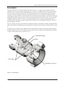
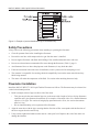
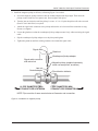
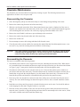
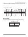
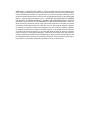
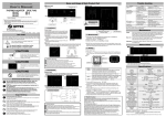
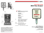
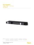
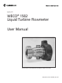
NUFLO™
WECO® 1502
Liquid Turbine Flowmeter
User Manual
APPROVED FOR PRESSURE EQUIPMENT DIRECTIVE (PED)
Manual No. 9A-10165002, Rev. 02
Technical Support Contact Information
Cameron
Measurement Systems Division
14450 John F. Kennedy Blvd.
Houston, TX 77032
Phone: 1-800-654-3760; 281-582-9500
Fax: 281-582-9599
NuFlo is a trademark of Cameron International Corporation (“Cameron”).
WECO is a registered trademark of FMC Technologies, Inc.
© 2008 Cameron International Corporation (“Cameron”). All information contained in this publication is
confidential and proprietary property of Cameron. Any reproduction or use of these instructions, drawings,
or photographs without the express written permission of an officer of Cameron is forbidden.
All Rights Reserved.
Printed in the United States of America.
Manual No. 9A-10165002, Rev. 02
September 2008
NuFlo™ WECO® 1502 Liquid Turbine Flowmeter
Table of Contents
Description.......................................................................................................................................................... 5
Safety Precautions.............................................................................................................................................. 6
Flowmeter Installation......................................................................................................................................... 6
Flowmeter Maintenance...................................................................................................................................... 8
Disassembling the Flowmeter....................................................................................................................... 8
Reassembling the Flowmeter....................................................................................................................... 8
Flow Rate Specifications..................................................................................................................................... 9
Table 1—Linear Flow Range ....................................................................................................................... 9
Replacement Kits................................................................................................................................................ 9
Table 2—Replacement Kits........................................................................................................................... 9
iii
NuFlo™ WECO® 1502 Liquid Turbine Flowmeter
iv
NuFlo™ WECO® 1502 Liquid Turbine Flowmeter
Description
The NuFlo™ WECO® 1502 Liquid Turbine Flowmeter (Figure 1) is a rugged versatile sensor capable of
handling a wide variety of liquids including many types of slurries and suspensions. The flowmeter contains
a rotor secured to a tungsten carbide shaft. The shaft is supported at each end in tungsten carbide bearings.
The rotor is made of a magnetic material, while the flowmeter body is non-magnetic. A magnetic pickup
consisting of a magnet and coil is mounted externally in the body in the same plane as the rotor. Fluid moving
through the flowmeter causes the rotor to rotate at a speed proportional to the fluid velocity. The rotor blades
cutting the magnetic field in the vicinity of the magnetic pickup create a frequency signal proportional to
the fluid velocity. This signal is used to represent flow rate and can be accumulated to totalize the volume of
liquid through the flowmeter.
For easy reference, the meter specifications to include part number, serial number, material, nominal diameter
(DN), and maximum working pressure are imprinted on a stainless steel tag on the meter body (Figure 2, page
6).
Each flowmeter is furnished with a calibration factor representing the number of pulses per gallon produced
during the calibration process. Precalibrated rotor and vane kits are available for field replacement (see Table
2, page 9). Meters and kits have a linearity of ±1%.
Flowmeter housing
Rotor
Flow vanes
Retainer ring (2 typ.)
Figure 1—Nomenclature
NuFlo™ WECO® 1502 Liquid Turbine Flowmeter
10101071 01
2SWU3394-07
Figure 2—Example of product identification tag on flowmeter body
Safety Precautions
Always observe the following precautions when installing or operating the flowmeter:
• Clean all upstream lines before installing the flowmeter.
• Do not blow out lines with compressed air or gas after the meter is installed.
• Do not slug the flowmeter with fluid. Initial filling of line with fluid should be done with care.
• Do not exceed maximum recommended flow rates through the flowmeter (Table 2, page 9).
• Avoid hammer blows or other sharp impacts on the flowmeter; it may break the shaft.
• If the end connection leaks at the time of installation, remove pressure before attempting to seal.
• The customer is responsible for ensuring chemical compatibility between the meter materials and any
fluids being metered.
• The meter will retain the temperature of the fluid. Use caution when touching the meter body.
Flowmeter Installation
Install the NuFlo™ WECO® 1502 Liquid Turbine Flowmeter as follows. The flowmeter may be oriented in a
vertical or horizontal position.
1. Install a straight section of pipe on either side of the meter.
•
This pipe must be the same nominal pipe size as the meter with a length of at least 10 pipe diameters
upstream and 5 pipe diameters downstream. (For example, a flowmeter with a 2-in. nominal diameter
requires a 2-in. pipe. The section of straight pipe upstream must be 20 in.; the section downstream
must be 10 in.)
•
Do not install throttling valves upstream of the flowmeter.
2. Align the meter bore with the pipe, ensuring that the direction of flow corresponds with the direction of
the arrow engraved on the meter body.
3. Using caution, tighten the hammer union nuts for a leak-proof seal. Impact to the side of the meter can
damage the internals.
NuFlo™ WECO® 1502 Liquid Turbine Flowmeter
4. Install the magnetic pickup as follows, referencing Figure 3 as needed:
a. Screw the magnetic pickup clockwise into the conduit adapter until finger-tight. Then rotate the
pickup counter-clockwise one quarter turn. Do not tighten with pliers.
b. Turn the jam nut clockwise until the pickup is secure. A ¾-in. 12-point deep thin wall socket wrench
(Part No. 9A-100013146) is required.
c. Attach the signal cable connector to the pickup and turn the swivel nut until the connection is snug.
Do not over-tighten.
d. Loosen the gland nut so that the weatherproof pickup adapter rotates freely without twisting the signal
cable.
e. Slip the weatherproof pickup adapter over the pickup and tighten.
f.
Tighten the gland nut until the rubber grommet seals around the signal cable.
Signal cable
Gland nut
Weatherproof pickup adapter
Signal cable connector
with swivel nut
Jam nut
Conduit adapter
10 PIPE DIAMETERS (MIN)
STRAIGHT PIPE UPSTREAM
Magnetic pickup (supplied separately;
meter can accept two, as shown)
Flow direction indicator
5 PIPE DIAMETERS (MIN)
STRAIGHT PIPE DOWNSTREAM
NOTE: Pipe must be of same nominal size as flowmeter end connection.
Figure 3—Installation of magnetic pickup
NuFlo™ WECO® 1502 Liquid Turbine Flowmeter
Flowmeter Maintenance
The flowmeter may be disassembled for inspection, cleaning or repair. The following instructions are
applicable to all meter sizes except as noted.
Disassembling the Flowmeter
1. Screw the magnetic pickup out of the meter body to avoid damage during handling of the meter.
2. Remove the retainer ring from one end of the meter body.
3. Slide the vane from the meter body. Note: Some slotted meters may require a slight twist of the vane to
align the vane with the slot in the meter body. (If the vane is stuck, insert a brass rod through the opposite
vane and through the rotor and drive the vane out by tapping on alternate blades of the vane.)
4. Remove the rotor. Handle it with care to prevent damage to the rotor shaft.
5. Remove the retainer ring from the other end of the meter body.
6. Remove the second vane.
7. Do not attempt to remove the bearings and thrust balls from the vanes.
8. Clean all parts with a solvent suitable for removing the material that has flowed through the meter. A cotton swab is very useful for cleaning the inside diameter of the bearings.
Important
If the meter internals are damaged, always replace the entire kit (Table 2, page 9). Never
exchange only the damaged piece. The kits are provided as a calibrated set of components. Accuracy will be sacrificed by replacing just individual parts.
Reassembling the Flowmeter
The meter is assembled in the following manner:
1. Note that the arrows that are cast or engraved on each part, indicating the direction of flow. When the meter is assembled, these arrowheads and the arrow engraved on the meter body (see flow direction indicator
in Figure 3, page 7) must point in the direction that product will flow through the meter.
2. Note that one of the blades on each vane has an arrow on it. Also note that retainer pins or notches are
provided at each end of the meter body. The marked blade must be inserted between these retainer pins or
notches that are opposite the conduit adapter (or on the bottom of the meter body). The meters are calibrated in this position, and should be reassembled in this position for the greatest accuracy.
3. Insert one of the vane assemblies in the meter body bore, taking care to orient the flow direction arrows
correctly. The vane should fit snugly but should not require excessive force to install. Install the retainer
ring.
4. Install the rotor, being careful to properly orient the direction arrow on the rotor. Care should be taken to
avoid chipping the rotor shaft. Tungsten carbide is very brittle.
5. Insert the second vane assembly. If this vane does not fall into position when placed in the meter body,
rotate the rotor, if possible, to align the bearing and rotor shaft. Do not attempt to drive the vane in, as this
will result in a broken rotor shaft. Install the retainer ring.
NuFlo™ WECO® 1502 Liquid Turbine Flowmeter
6. Spin the rotor by hand, making sure that the rotor moves freely. If the rotor will not turn or stops abruptly,
the meter should be disassembled and checked.
7. The meter is now ready for installation. Follow the flowmeter installation procedure as described on page
6.
Flow Rate Specifications
Table 1—Linear Flow Range1,2
Flowmeter
Size
in.
(mm)
1
(25)
1½
(38)
2
(51)
3
(76)
1.
2.
GPM
M /hr
BPD
5 - 50
1 .14 - 11.36
170 – 1700
15 - 180
3.41 - 40.88
515-6000
40 - 400
9.09 - 90.85
1300-13000
80 - 800
18.16-181.66
2750 – 27500
3
Nominal(2)
Cal. Factor
pulses/gal
(pulses x 1000/m3)
Max. Output
Frequency
pulses/sec
900
(238)
325
(86)
55
(14.5)
57
(15.2)
750
975
365
760
ΔP at
Max. Flow(2)
psi
(kPa)
20.0
(138)
16.0
(110)
22.0
(152)
20.0
(138)
The linear flow range of liquids with non-lubricating characteristics is limited to the upper 60% of rating.
Based on water.
Replacement Kits
Each replacement kit contains a rotor, two vane assemblies, two retainer rings, and a calibration tag. All
components are calibrated as a set and should be installed as a set. Components should not be installed
individually.
Table 2—Replacement Kits
Meter Size (in.)
Kit Part Number
1
1-1/2
2
3
9A-100003527
9A-100003469
9A-100003474
9A-100003470
NuFlo™ WECO® 1502 Liquid Turbine Flowmeter
10
WARRANTY - LIMITATION OF LIABILITY: Seller warrants only title to the products, software, supplies and materials and that, except as to software, the same are free from defects
in workmanship and materials for a period of one (1) year from the date of delivery. Seller
does not warranty that software is free from error or that software will run in an uninterrupted
fashion. Seller provides all software “as is”. THERE ARE NO WARRANTIES, WPRESS
OR IMPLIED, OF MERCHANTABILITY, FITNESS OR OTHERWISE WHICH EXTEND
BEYOND THOSE STATED IN THE IMMEDIATELY PRECEDING SENTENCE. Seller’s liability and Buyer’s exclusive remedy in any case of action (whether in contract, tort, breach
of warranty or otherwise) arising out of the sale or use of any products, software, supplies,
or materials is expressly limited to the replacement of such products, software, supplies,
or materials on their return to Seller or, at Seller’s option, to the allowance to the customer
of credit for the cost of such items. In no event shall Seller be liable for special, incidental,
indirect, punitive or consequential damages. Seller does not warrant in any way products,
software, supplies and materials not manufactured by Seller, and such will be sold only with
the warranties that are given by the manufacturer thereof. Seller will pass only through to
its purchaser of such items the warranty granted to it by the manufacturer.