1
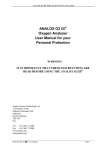
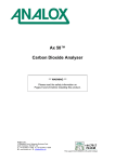
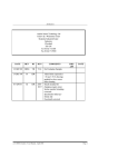
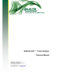
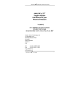
Analox 101D2 Portable - Oxygen Monitor
User Manual
Analox Ltd.
15 Ellerbeck Court, Stokesley Business Park
North Yorkshire, TS9 5PT, UK
T: +44 (0)1642 711400 F: +44 (0)1642 713900
W: www.analox.net E: [email protected]
This support line is closed on UK public holidays
Analox 101D2 Portable - Oxygen Monitor
User Manual
List of Contents
1
2
3
4
5
6
7
8
9
10
Introduction .................................................................................................................................... 3
Controls ........................................................................................................................................... 4
Battery Check ................................................................................................................................. 5
Calibration....................................................................................................................................... 6
Alarm Operation ............................................................................................................................ 7
Alarm Setting ................................................................................................................................. 8
Sensor Replacement ..................................................................................................................... 9
Trouble shooting .......................................................................................................................... 10
Specifications ............................................................................................................................... 14
Analox Oxygen Compensation Chart .................................................................................. 15
Document Ref: 1D2-800-02 - March 2015
Page 1
Analox 101D2 Portable - Oxygen Monitor
User Manual
Document Ref: 1D2-800-02 - March 2015
Page 2
Analox 101D2 Portable - Oxygen Monitor
User Manual
1
Introduction
1.1.1
The ANALOX 101D2 Oxygen Analyser is a battery powered, portable instrument
which provides a continuous digital display of the Oxygen concentration, in the gas
sample, presented to the front surface of the sensor unit. The instrument has two
ranges:
0.01% - 19.99% and 0.1% - 100.0%
1.1.2
The sensor assembly incorporates advanced circuit design which provides
automatic temperature compensation over the range -10°C to 40°C. The
instrument is easy to calibrate, requiring only a single adjustment and user
settable High and Low, audible and visual alarms are fitted as standard.
1.1.3
Optional extra facilities can be specified at time
analogue output voltage, relays which operate in
Sensor Input to accommodate a remote loop
Optional extras require the fitting of the 0 – 30vDC
of ordering. These include an
alarm conditions, a 4 – 20mA
powered Sensor. Transmitter.
external power facility.
Document Ref: 1D2-800-02 - March 2015
Page 3
Analox 101D2 Portable - Oxygen Monitor
User Manual
2
Controls
Document Ref: 1D2-800-02 - March 2015
Page 4
Analox 101D2 Portable - Oxygen Monitor
User Manual
3
3.1
Battery Check
If the internal battery voltage falls below a pre-set threshold, approximately 5 volts,
then the LCD display on the instrument front panel will alternate between its normal
reading and ‘1888’. The Instrument should not be used when this occurs since
the indicated value of Oxygen concentration may not be accurate.
Document Ref: 1D2-800-02 - March 2015
Page 5
Analox 101D2 Portable - Oxygen Monitor
User Manual
4
Calibration
4.1
Zero Check: Select the 0 – 19.99% range using the switch on the front panel and
remove the sensor jack plug, from the socket on the front panel. The LED should
read 0.00 ± 0.02. This checks the instrument zero and is the same as the theoretical
zero voltage output of a sensor, when it is subjected to as containing no Oxygen.
Alternatively, Pure Nitrogen or Helium or other Oxygen free gas may be passed
across the sensor, at a flow rate of approx. 60 Litres/Hour for about 3 minutes. The
Instrument reading should not be greater than about 0.03% (300ppm), depending
on the purity of the gas being used and the sensor performance.
4.2
Span Adjustment: this can be carried out in two ways.
4.2.1
Select the 0 – 100 range and expose the sensor to normal ambient atmosphere.
When the reading on the display is steady, adjust the ‘CAL’ control on the
Instrument front panel until the display reads 20.9. Turning the control clockwise
will increase the reading. This completes the calibration process.
NOTE: High humidity decreases Oxygen levels in the atmosphere please refer to
the humidity chart in 10.0, calibrate using procedure 4.2.2.
4.2.2
Using a known accurate Oxygen/Nitrogen gas mixture, select the range most
appropriate to the gas concentration. Fit a flow adaptor to the sensor and pass the
gas at a flow rate of about 60 Litres/Hour, for about 5 minutes. When the Reading
on the display is steady, adjust the ‘CAL’ control on the front panel until the
reading on the display agrees with the Oxygen concentration of the gas being
used. Clockwise rotation of the control increases the reading. This completes the
calibration process.
If the desired readings cannot be obtained, then it is likely that the sensor has
come to the end of its life and should be replaced.
NOTE: The Instrument does not need to be calibrated on both ranges.
Document Ref: 1D2-800-02 - March 2015
Page 6
Analox 101D2 Portable - Oxygen Monitor
User Manual
5
Alarm Operation
5.1
If an alarm condition occurs, the internal audible buzzer will sound intermittently
and the appropriate LED will flash.
5.2
The audible alarm may then be silenced by pressing the ‘MUTE’ button on the front
panel. If the reading is still in the alarm condition, the LED will continue to flash until
the Oxygen concentration returns within the normal band. The LED will then turn off.
5.3
If an alarm condition occurs and the Oxygen concentration returns to normal before
the ‘MUTE’ button is pressed, then the audible and visual alarms will remain active,
until the ‘MUTE’ button is pressed. This facility allows the user to be aware of an
alarm occurring whilst the instrument was unattended.
5.4
The alarms have a built-in Hysteresis of approximately 0.3% O2 to overcome
nuisance alarm triggering when measuring near either set-point. This means that if
a high alarm occurs with a set point of 23.0% then having acknowledged the alarm
by pressing ‘MUTE’ button, the alarm state will not clear until the Oxygen level drops
to below 22.7%
Document Ref: 1D2-800-02 - March 2015
Page 7
Analox 101D2 Portable - Oxygen Monitor
User Manual
6
Alarm Setting
6.1
Before any adjustments are carried out to the ‘SET ALARM’ controls, the user should
release the locks on the control knobs. This is done by moving the small lever
located at the edge of the control downward until the knob moves freely. After
adjustment the lock should be reset to prevent accidental movement.
6.2
The ‘SET HI’ / ‘SET LO’ toggle switch is normally spring biased to its central position,
and in this position, displays measured Oxygen concentration. The Hi alarm trip
point may be reset by moving and holding the switch upward and adjusting the ‘SET
HI ALARM’ control until the desired set point is displayed on the LCD. The Lo alarm
trip point may be reset by moving and holding the switch downward and adjusting
the ‘SET LO ALARM’ control until the desired set point is displayed on the LCD.
Alarm trip points may only be set to a resolution of 0.1% O2. If the instrument is
being used on the 0 – 19.99% range then during the adjustment procedure, the
display will be automatically adjusted to read the correct resolution.
6.3
If the user only requires to check the present alarm set points, then this may be
done by just pressing the ‘SET HI’/‘SET LO’ switch to the appropriate position, and
reading the value on the LCD.
Document Ref: 1D2-800-02 - March 2015
Page 8
Analox 101D2 Portable - Oxygen Monitor
User Manual
7
Sensor Replacement
7.1
When the instrument can no longer be calibrated by adjustment of the ‘CAL’ control,
it is possible that the Oxygen Sensor unit is exhausted and should be replaced.
7.2
The ANALOX 9212-4 Sensor Assembly has a life of approximately 3 years in normal
air but this will be reduced if it is constantly exposed to higher concentrations of
Oxygen. Conversely, if the sensor is normally exposed to lower concentrations of
Oxygen, its life may be extended.
7.3
The sensor must be replaced with an Analox Oxygen sensor type 9212 – 4, as this
sensor is especially manufactured for this
instrument.
7.4
There are no serviceable parts in the sensor and cable assembly – the entire unit
must be replaced.
7.5
The sensor in the 101 D2 is an electrochemical device and contains a caustic
electrolyte. Always check to make sure that it is not leaking and do not allow it onto
any part of your body or clothing. In the event that you do come into contact with
the electrolyte wash the contaminated part with copious amounts of water – see
safety information.
Warning
If after handling the sensor you fingers or
other parts of your body feels slippery or
stings, wash with a lot of water.
If stinging persists get medical attention!
Document Ref: 1D2-800-02 - March 2015
Page 9
Analox 101D2 Portable - Oxygen Monitor
User Manual
8
Trouble shooting
SYMPTOM
REASON
SOLUTION
Battery Symbol
Low Battery
Change battery
LED does not read
000 ± 0.02
Requires offset adjust
See instructions in 8.1
No display
Switched off
Bad connection
Switch on
Check display connection
Check battery connection
Zero reading
Sensor disconnected
Sensor expired
Check connection
Change sensor
Reading erratic
Pressure on sensor
Radio transmission
Sensor old or faulty
Condensation on sensor
Check Flow
Move unit away
Change sensor
Dry sensor face
Reading does not change
When calibration pot is
turned.
Faulty connections
Sensor failure
Check connections
Change sensors
Display segments missing
Display faulty
Return to dealer
Will not calibrate
Sensor faulty
Sensor not in air
High altitude
Change sensor
Check flow adapter
Calculate percent
Equivalent = 20.9% bar
Reading drifts
Rapid temperature change
Do not move analyser
from one temperature to
another immediately
before use.
Document Ref: 1D2-800-02 - March 2015
Page 10
Analox 101D2 Portable - Oxygen Monitor
User Manual
8.1
8.1.1
Trouble shooting (continued)
In order to access the interior of the instrument the top cover requires removal. To
remove the top cover ensure the instrument is switched off and remove the four
screws located in the recesses in the base and the four rectangular rubber feet.
The top cover is retained by four internal catches, which can be seen at the bottom
of the rectangular holes which normally hold the rubber feet. These catches can be
released by using the green tool provided with the instrument, or a suitable
screwdriver. Lay the instrument on its side and insert the tool in one of the REAR
holes keeping the bevelled edge toward the rear of the instrument. Whilst holding
the instrument firmly, push the tool toward the top over and gently ease the rear
corner of the top away from the body. Repeat the process on the other REAR
CATCH. Release the front catches in a similar manner and the top cover may then
be removed.
WARNING: UNDER NO CIRCUMSTANCES SHOULD ANY ADJUSTMENTS OTHER
THAN THOSE OUTLINED IN THIS PROCEDURE BE MADE TO OTHER CONTROLS IN
THE INSTRUMENT. ANY ALTERATION OF OTHER CONTROLS WILL AFFECT THE
OPERATION AND ACCURACY OF THE INSTRUMENT AND THE SUPPLIER CANNOT BE
HELD RESPONSIBLE.
8.1.2
ADJUSTMENT PROCEDURE.
The potentiometer that requires adjustment is VR2. This is located on the main
printed circuit board SA004B/1. Adjacent to the front panel is a line of five
potentiometers, VR2 is the second potentiometer from the end nearest the front
panel. (See drawing 8.1.4.)
8.1.3
RE-ASSEMBLY OF THE BOX
Place the top cover loosely in position, easing the front edge groove of the cover
into the tongue on the instrument body. Press the top cover down and forward
until the retaining latches ‘click’ into position. Replace the four securing screws in
the base of the instrument and fit the rubber feet in the rectangular holes.
Document Ref: 1D2-800-02 - March 2015
Page 11
Analox 101D2 Portable - Oxygen Monitor
User Manual
8.1.4
OVERLAY DRAWING
Document Ref: 1D2-800-02 - March 2015
Page 12
Analox 101D2 Portable - Oxygen Monitor
User Manual
Warranty Information
We provide the following Warranties for the Analox 101D2:
A 2 year graded sensor warranty.
A 1 year electronics warranty.
In both cases the Warranty period runs from the date of our Invoice.
We warrant that the equipment will be free from defects in workmanship and
materials.
The Warranty does not extend to and we will not be liable for defects caused by
the effects of normal wear and tear, erosion, corrosion, fire, explosion, misuse,
use in any context or application for which the equipment is not designed or
recommended, or unauthorised modification.
Following a valid Warranty claim in accordance with the above, the equipment,
upon return to us, would be repaired or replaced without cost or charge but in our
discretion we may elect instead to provide to you whichever is the lesser of the
cost of replacement or a refund of net purchase price paid as per our Invoice on
initial purchase from us. We shall have no liability for losses, damages, costs or
delays whatsoever. We shall have no liability for any incidental or consequential
losses or damages.
All express or implied warranties as to satisfactory or
merchantable quality, fitness for a particular or general purpose or otherwise are
excluded and no such Warranties are made or provided, save as set out in this
Clause 7.
In order to effectively notify a Warranty claim, the claim with all relevant
information and documentation should be sent in writing to:
Analox Sensor Technology Limited
15 Ellerbeck Court
Stokesley Business Park
Stokesley
North Yorkshire
TS9 5PT
Or by e-mail to : [email protected]
Or by Fax to : +44 1642 713900
We reserve the right to require from you proof of dispatch to us of the notification
of Warranty claim by any of the above alternative means.
The equipment should not be sent to us without our prior written authority. All
shipping and Insurance costs of returned equipment are to be borne by you and
at your risk. All returned items must be properly and sufficiently packed.
Document Ref: 1D2-800-02 - March 2015
Page 13
Analox 101D2 Portable - Oxygen Monitor
User Manual
9
Specifications
Ranges
0.01% - 19.99% at Atmospheric Pressure
0.1% - 100.0% at Atmospheric Pressure
Minimum Reading
0.01% O2
Accuracy
± 1% of Readout
Temperature Effect
± 0.1% of Readout per °C
Sensor Life
2 years in Air (20.9%)
Battery
4 x MN1500 Alkaline Cells
Battery Life
Approx. 1 month of continuous use reducing with
Alarm Activation
Dimensions
Depth Overall:
Height Overall:
Width Overall:
Weight:
Document Ref: 1D2-800-02 - March 2015
Page 14
205mm
68mm
148mm
700gms (Incl. Battery)
Analox 101D2 Portable - Oxygen Monitor
User Manual
10 Analox Oxygen Compensation Chart
Document Ref: 1D2-800-02 - March 2015
Page 15
Analox 101D2 Portable - Oxygen Monitor
User Manual
Warning
These instructions should be read and understood by all individuals who will
Be responsible for the operation of this analyser. The actions taken as a result of the
measured Oxygen readings must be in strict accordance with the Company or Country
regulations.
Document Ref: 1D2-800-02 - March 2015
Page 16