1
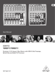
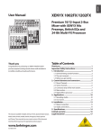
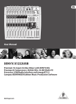
1002FX/1202FX XENYX Users Manual Version 1.0 January 2006 XENYX 1002FX/1202FX IMPORTANT SAFETY INSTRUCTIONS DETAILED SAFETY INSTRUCTIONS: 1) Read these instructions. 2) Keep these instructions. 3) Heed all warnings. 4) Follow all instructions. CAUTION: To reduce the risk of electric shock, do not remove the top cover (or the rear section). No user serviceable parts inside; refer servicing to qualified personnel. 5) Do not use this apparatus near water. 6) Clean only with dry cloth. 7) Do not block any ventilation openings. Install in accordance with the manufacturers instructions. WARNING: To reduce the risk of fire or electric shock, do not expose this appliance to rain and moisture. The apparatus shall not be exposed to dripping or splashing and no objects filled with liquids, such as vases, shall be placed on the apparatus. This symbol, wherever it appears, alerts you to the presence of uninsulated dangerous voltage inside the enclosurevoltage that may be sufficient to constitute a risk of shock. This symbol, wherever it appears, alerts you to important operating and maintenance instructions in the accompanying literature. Please read the manual. 8) Do not install near any heat sources such as radiators, heat registers, stoves, or other apparatus (including amplifiers) that produce heat. 9) Do not defeat the safety purpose of the polarized or grounding-type plug. A polarized plug has two blades with one wider than the other. A grounding type plug has two blades and a third grounding prong. The wide blade or the third prong are provided for your safety. If the provided plug does not fit into your outlet, consult an electrician for replacement of the obsolete outlet. 10) Protect the power cord from being walked on or pinched particularly at plugs, convenience receptacles, and the point where they exit from the apparatus. 11) Only use attachments/accessories specified by the manufacturer. 12) Use only with the cart, stand, tripod, bracket, or table specified by the manufacturer, or sold with the apparatus. When a cart is used, use caution when moving the cart/apparatus combination to avoid injury from tip-over. 13) Unplug this apparatus during lightning storms or when unused for long periods of time. 14) Refer all servicing to qualified service personnel. Servicing is required when the apparatus has been damaged in any way, such as power supply cord or plug is damaged, liquid has been spilled or objects have fallen into the apparatus, the apparatus has been exposed to rain or moisture, does not operate normally, or has been dropped. 15) CAUTION - These service instructions are for use by qualified service personnel only. To reduce the risk of electric shock do not perform any servicing other than that contained in the operation instructions unless you are qualified to do so. 2 XENYX 1002FX/1202FX FOREWORD Dear Customer, Im sure youre one of those people who have devoted themselves body and soul to your chosen area and no doubt this has made you an expert in your field. Well, for over 30 years, my passion has been music and electronics. This not only led me to establish BEHRINGER, but also enabled me to share my enthusiasm with our employees. During all the years Ive been involved with studio technology and end users, I have developed a feel for the things that really count, such as sound quality, reliability and ease of use. What is more, I have always had the desire to test the boundaries of what is technically feasible. It was precisely this motivation that prompted me to start work on a new series of mixing consoles. Since our EURORACKs had already set new standards world-wide, I knew the development objectives behind the next generation of mixing consoles had to be especially ambitious. Thus, the concept and design of the new XENYX mixing consoles bear my signature. The design work, the entire circuit diagram and PCB development, and even the mechanical concepts are my own work. I carefully selected each individual component with the aim of pushing the mixing consoles combining analog and digital technologies to their limits. TABLE OF CONTENTS 1. INTRODUCTION ......................................................... 4 1.1 General mixing console functions .................................. 4 1.2 The users manual .......................................................... 4 1.3 Before you get started ................................................... 5 1.3.1 Shipment ............................................................... 5 1.3.2 Initial operation ...................................................... 5 1.3.3 Online registration ................................................ 5 2. CONTROL ELEMENTS AND CONNECTORS .............. 5 2.1 2.2 2.3 2.4 2.5 Mono channels ............................................................... 5 Stereo channels ............................................................. 6 Connector array of the main section ............................. 7 Main section .................................................................... 7 Digital effects processor ................................................ 8 3. APPLICATIONS .......................................................... 9 3.1 Recording studio ............................................................ 9 3.2 Live sound .................................................................... 10 4. INSTALLATION ......................................................... 11 4.1 Mains connection ......................................................... 11 4.2 Audio connections ....................................................... 11 5. SPECIFICATIONS ..................................................... 12 6. WARRANTY .............................................................. 13 My vision was to enable you, the user, to give free rein to your true potential and creativity. The result is mixing consoles that combine incredible performance with intuitive operability. They cannot fail to impress with their extremely flexible routing possibilities plus a fantastic wealth of functions. Innovative technologies, such as the completely new XENYX Mic Preamps and the British EQs, guarantee optimum sound quality. And extraordinarily high-quality components provide unrivalled reliability, even under extreme loads. Thanks to the quality and ease of use of your new XENYX mixing console youll soon come to appreciate that I, both personally and in my capacity as musician and sound engineer, put you, the end user, first and that these products were only possible because of the passion and the attention to detail that went into them. Thank you for the confidence you have placed in us by purchasing the XENYX mixing console. I should also like to thank all those who, with their personal commitment and passion, have helped me create this impressive series of mixing consoles. Kindest regards, Uli Behringer 3 XENYX 1002FX/1202FX output voltage is very low and therefore susceptible to interference. Therefore, mic signal voltage is amplified directly at the mixer input to a higher signal level that is less prone to interference. This higher, interference-safe signal level has to be achieved through amplification using an amplifier of the highest quality in order to amplify the signal and add as little noise to it as possible. The XENYX Mic Preamp performs this role beautifully, leaving no traces of noise or sound coloration. Interference that could take place at the preamplification level could affect signal quality and purity, and would then be passed on to all other devices, resulting in inaccurate sounding program during recording or playback. 1. INTRODUCTION Congratulations! In purchasing our XENYX 1002FX/1202FX you have acquired a mixing console whose small size belies its incredible versatility and audio performance. The BEHRINGER XENYX mixing console offers you premiumquality microphone preamplifiers with optional phantom power supply, balanced line inputs and the ability to connect external effects processors. Because of its extensive and carefully thought-out routing possibilities, your XENYX lends itself equally to both live and studio use. The XENYX Series represents a milestone in the development of mixing console technology. With the new XENYX microphone preamps including phantom power as an option, balanced line inputs and a powerful effects section, the mixing consoles in the XENYX Series are optimally equipped for live and studio applications. Owing to state-of-the-art circuitry your XENYX console produces a warm analog sound that is unrivalled. With the addition of the latest digital technology these best-in-class consoles combine the advantages of both analog and digital technology. The microphone channels feature high-end XENYX Mic Preamps that compare well with costly outboard preamps in terms of sound quality and dynamics and boast the following features: s 130 dB dynamic range for an incredible amount of headroom s A bandwidth ranging from below 10 Hz to over 200 kHz for crystal-clear reproduction of even the finest nuances s The extremely low-noise and distortion-free circuitry guarantees absolutely natural and transparent signal reproduction s They are perfectly matched to every conceivable microphone with up to 60 dB gain and +48 volt phantom power supply s They enable you to use the greatly extended dynamic range of your 24-bit/192-kHz HD recorder to the full, thereby maintaining optimal audio quality British EQ The equalizers used for the XENYX Series are based on the legendary circuitry of top-notch consoles made in Britain, which are renowned throughout the world for their incredibly warm and musical sound character. Even with extreme gain settings these equalizers ensure outstanding audio properties. Multi-effects processor Additionally, your XENYX mixing console has an effects processor with 24-bit A/D and D/A converters included, which gives you 100 presets producing first-class reverb, delay and modulation effects plus numerous multi-effects in excellent audio quality. + CAUTION! We should like to draw your attention to the fact that extreme volumes may damage your hearing and/or your headphones or loudspeakers. Turn the MAIN MIX control and PHONES control in the main section fully counterclockwise before you switch on the unit. Always be careful to set appropriate volume levels. 1.1 General mixing console functions A mixing console fulfils three main functions: s Signal processing: Level-setting Signals fed into the mixer using a DI-box (Direct Injection) or the output of a sound card or a keyboard, often have to be adjusted to the operating level of your mixing console. Frequency response correction Using the equalizers found in each channel strip, you can simply, quickly and effectively adjust the way a signal sounds. s Signal distribution: Individual, processed signals from the channel strips are compiled on busses and are fed into the main section for further processing. Connections for recording equipment, power amplifiers, headphones as well as CD/tape connectors are available here. The mix is sent to the internal FX processors or external effects processors via aux sends and returns. Similarly, a mix can be created for the musicians on the stage (monitor mix). s Mix: All other mixing console functions fall under this vital category. Creating a mix means primarily adjusting the volume levels of individual instruments and voices to one another as well as giving them the appropriate weight within the overall frequency spectrum. Likewise, youll have to sensibly spread individual voices across the stereo image of a signal. At the end of this process, adjusting the level of the entire mix to other equipment in the signal path is required (e. g. recorder/crossover/amplifier). The interface of BEHRINGER mixing consoles is optimized for these tasks, enabling you to easily keep track of the signal path. 1.2 The users manual The users manual is designed to give you both an overview of the controls, as well as detailed information on how to use them. In order to help you understand the links between the controls, we have arranged them in groups according to their function. If you need to know more about specific issues, please visit our website at http://www.behringer.com. Additional information and explanations about various music industry/audio technology terminology can be found on individual product pages as well as in the glossary area of www.behringer.com. + The block diagram supplied with the mixing console gives you an overview of the connections between the inputs and outputs, as well as the associated switches and controls. For the moment, just try and trace the signal path from the microphone input to the FX SEND connector. Dont be put off by the huge range of possibilities; its easier than you think! If you look at the overview of the controls at the same time, youll be able to quickly familiarize yourself with your mixing console and youll soon be making the most of all its many possibilities. Preamplification Microphones convert sound waves into voltage that has to be amplified several-fold; then, this voltage is turned into sound that is reproduced in a loudspeaker. Because microphone capsules are very delicate in their construction, 4 1. INTRODUCTION XENYX 1002FX/1202FX 1.3 Before you get started 2. CONTROL ELEMENTS AND CONNECTORS 1.3.1 Shipment Your mixing console was carefully packed in the factory to guarantee safe transport. Nevertheless, we recommend that you carefully examine the packaging and its contents for any signs of physical damage that may have occurred during transit. + + + + + This chapter describes the various control elements of your mixing console. All controls, switches and connectors will be discussed in detail. 2.1 Mono channels If the unit is damaged, please do NOT return it to us, but notify your dealer and the shipping company immediately, otherwise claims for damage or replacement may not be granted. To assure optimal protection of your XENYX during use or transport, we recommend utilizing a carrying case. Please always use the original packaging to avoid damage due to storage or shipping. Never let unsupervised children play with the XENYX or with its packaging. Please dispose of all packaging materials in an environmentally-friendly fashion. 1.3.2 Initial operation Be sure that there is enough space around the unit for cooling purposes and to avoid overheating please do not place your mixing console on high-temperature equipment such as radiators or power amps. + + + Never connect the XENYX to the power supply unit when the latter is connected to the mains! First connect the power supply unit to the console, then connect the power supply unit to the mains. Please make sure that all units have a proper ground connection. For your own safety, never remove or disable the ground conductor from the unit or on the AC power cord. The unit should always be connected to a mains socket outlet with a protective earthing connection. When installing the product, ensure the appliance coupler or power cord is easily accessible for disconnecting the unit from mains. 1.3.3 Online registration Please, do remember to register your new BEHRINGER equipment right after your purchase by visiting www.behringer.com (alternatively www.behringer.de) and kindly read the terms and conditions of our warranty carefully. Should your BEHRINGER product malfunction, our goal is to have it repaired as quickly as possible. To arrange for warranty service, please contact the retailer from whom the equipment was purchased. Should your BEHRINGER dealer not be located in your vicinity, you may directly contact one of our subsidiaries. Corresponding contact information is included in the original equipment packaging (Global Contact Information/European Contact Information). Should your country not be listed, please contact the distributor nearest you. A list of distributors can be found in the support area of our website (www.behringer.com). Registering your purchase and equipment with us helps us process your repair claims quicker and more efficiently. Thank you for your cooperation! Fig. 2.1: Connectors and controls on the mono channels MIC Each mono input channel offers a balanced microphone input via the XLR connector and also features switchable +48 V phantom power supply for condenser microphones. The XENYX preamps provide undistorted and noise-free gain as is typically known only from costly outboard preamps. + Please mute your playback system before you activate the phantom power supply to prevent switch-on thumps being directed to your loudspeakers. Please also note the instructions in chapter 2.4 Main section. LINE IN Each mono input also features a balanced line input on a ¼" connector. Unbalanced devices (mono connectors) can also be connected to these inputs. + Please remember that you can only use either the microphone or the line input of a channel at any one time. You can never use both simultaneously! 2. CONTROL ELEMENTS AND CONNECTORS 5 XENYX 1002FX/1202FX TRIM Use the TRIM control to adjust the input gain. This control should always be turned fully counterclockwise whenever you connect or disconnect a signal source to one of the inputs. The scale has 2 different value ranges: the first value range (+10 to +60 dB) refers to the MIC input and shows the amplification for the signals fed in there. CLIP The CLIP-LEDs of the mono channels illuminate when the input signal is driven too high, which could cause distortion. If this happens, use the TRIM control to reduce the preamp level until the LED does not light anymore. 2.2 Stereo channels The second value range (+10 to -40 dBu) refers to the line input and shows its sensitivity. The settings for equipment with standard line-level signals (-10 dBV or +4 dBu) look like this: While the TRIM control is turned all the way down, connect your equipment. Set the TRIM control to the external devices standard output level. If that unit has an output signal level display, it should show 0 dB during signal peaks. For +4 dBu, turn up TRIM slightly, for -10 dBV a bit more. Tweaking is done using the CLIP LED. EQ All mono input channels include a 3-band equalizer. All bands provide boost or cut of up to 15 dB. In the central position, the equalizer is inactive. The circuitry of the British EQs is based on the technology used in the best-known top-of-the-line consoles and providing a warm sound without any unwanted side effects. The result are extremely musical equalizers which, unlike simple equalizers, cause no side effects such as phase shifting or bandwidth limitation, even with extreme gain settings of ±15 dB. The upper (HIGH) and the lower band (LOW) are shelving filters that increase or decrease all frequencies above or below their cut-off frequency. The cut-off frequencies of the upper and lower band are 12 kHz and 80 Hz respectively. The MID band is configured as a peak filter with a center frequency of 2.5 kHz. Unlike shelving filters, the peak filter processes a frequency range that extends upwards and downwards around its middle frequency. LOW CUT In addition, the mono channels are equipped with a steep LOW CUT filter (slope at 18 dB/oct., -3 dB at 75 Hz) designed to eliminate unwanted low-frequency signal components. These can be noises created by hand-held microphones, subsonic noise or plosive sounds created by highly sensitive microphones. FX FX sends enable you to feed signals via a variable control from one or more channels and sum these signals to a bus. The bus appears at the consoles FX send output and can be fed from there to an external effects device. The return from the effects unit is then brought back into the console on the stereo channels. Each FX send is mono and features up to +15 dB gain. As the name suggests, the FX sends of the XENYX mixing consoles are intended to drive effects devices (reverb, delay, etc.) and are therefore configured post-fader. This means that the mix between dry signal and effect remains at the level determined by the channels aux send, irrespective of the channel fader setting. If this were not the case, the effects signal of the channel would remain audible even when the fader is lowered to zero. With XENYX mixing consoles, the channel fader is called LEVEL control. In the 1002FX/1202FX, the FX send is routed directly to the built-in effects processor. To make sure that the effects processor receives an input signal, you shouldnt turn this control all the way to the left (-oo). PAN The PAN control determines the position of the channel signal within the stereo image. This control features a constant-power characteristic, which means the signal is always maintained at a constant level, irrespective of position in the stereo panorama. LEVEL The LEVEL control determines the level of the channel signal in the main mix. + 6 Attention: Since the FX path for the effect processor is connected post-fader, the LEVEL control has to be turned up in order to get this channels signal to the effects processor! Fig. 2.2: Connectors and controls on the stereo channels LINE IN Each stereo channel has two balanced line level inputs on ¼" connectors for left and right channels. If only the connector marked L (left) is used, the channel operates in mono. The stereo channels are designed to handle typical line level signals. Both inputs will also accept unbalanced connectors. FX The FX send of the stereo channels functions similar to that of the mono channels. However, since the FX send bus is mono, a mono sum is first taken from the stereo input before it is sent to the FX bus. BAL The BAL(ANCE) control determines the levels of left and right input signals relative to each other before both signals are then routed to the main stereo mix bus. If a channel is operated in mono via the left line input, this control has the same function as the PAN control used in the mono channels. LEVEL The LEVEL control determines the volume of the channel being sent to the main mix. +4/-10 The stereo inputs of the XENYX have an input sensitivity switch which selects between +4 dBu and -10 dBV. At -10 dBV (homerecording level), the input is more sensitive (requires less level to drive it) than at +4 dBu (studio level). 2. CONTROL ELEMENTS AND CONNECTORS XENYX 1002FX/1202FX 2.3 Connector array of the main section CD/TAPE INPUT The CD/TAPE INPUTs are used to bring an external signal source (e.g. CD player, tape deck, etc.) into the console. They can also be used as a standard stereo line input, so the output of a second XENYX or BEHRINGER ULTRALINK PRO MX882 can be connected. Alternatively the line or tape output of a hi-fi amplifier with source selection switch could also be hooked up here, allowing you to easily listen to additional sources (e.g. cassette recorder, minidisk player, sound card etc.). TAPE OUTPUT These connections are laid out as RCA connectors and are wired parallel to MAIN OUT. Connect the inputs of a computer sound card or a recorder here. The output signal level is set up using the highly accurate MAIN MIX fader. 2.4 Main section Fig.2.3: Connectors of the main section FX SEND The FX SEND connector outputs the signal you picked up from the individual channels using the FX controls. You can connect this to the input of an external effects device in order to process the FX bus master signal. Once an effects mix is created, the processed signal can then be routed from the effects device outputs back into a stereo input. + + + If the connected effects processor receives no input signal, the FX SEND control is probably too low. This also goes for the built-in effects processor. Adjust your external effects processor to 100% wet (effects signal only), because the effects signal is added to the main mix along with the dry channel signals. In this instance, the FX control of the channel being used as an effects return should be turned fully counterclockwise, otherwise feedback problems can occur! PHONES/CONTROL ROOM OUT The stereo PHONES connector (at the top of the connector panel) is where headphones are connected. The unbalanced CONTROL ROOM OUT connectors carry the summed effects and main mix signals as well as soloed channel signals. The PHONES/CONTROL ROOM control in the main section adjusts the level of both headphones and main monitor outputs. MAIN OUT The MAIN OUT connectors are unbalanced mono connectors. The main mix signal appears here at a level of 0 dBu. The MAIN MIX fader adjusts the volume of these outputs. Depending on how you wish to use your mixer and which gear you own, you can connect the following equipment: Fig. 2.4: Control elements of the main section +48 V The red +48 V LED lights up when the phantom power is turned on. Phantom power is required to operate condenser microphones and is activated using the +48 V switch located above the +48 V LED. + Live PA systems: A stereo dynamics processor (optional), stereo equalizer (optional) and the stereo power amplifier for full-range loudspeakers with passive crossovers. If you wish to use multi-way loudspeaker systems without an integrated crossover, you have to use an active crossover and several power amplifiers. Often, limiters are already built into active crossovers (e.g. BEHRINGER SUPER-X PRO CX2310 and ULTRADRIVE PRO DCX2496). Active crossovers are implemented directly before the power amplifier, and they divide the frequency range into several segments that are first amplified in the amplifiers and then passed on to the corresponding loudspeakers. Recording: For mastering, using a stereo compressor such as the COMPOSER PRO-XL MDX2600 can be recommended. Use it to custom-tailor the dynamic characteristics of your signal to the dynamic range of the recording equipment you are using. The signal is in this case passed on from the compressor into the recorder. + Connect microphones before you switch on the phantom power supply. Please do not connect microphones to the mixer (or the stagebox/ wallbox) while the phantom power supply is switched on. In addition, the monitor/PA loudspeakers should be muted before you activate the phantom power supply. After switching on, wait approx. one minute to allow for system stabilization. Caution! You must never use unbalanced XLR connectors (PIN 1 and 3 connected) on the MIC input connectors if you want to use the phantom power supply. POWER The blue POWER LED indicates that the console is powered on. LEVEL INDICATOR The 4-segment display accurately displays the relevant signal level. 2. CONTROL ELEMENTS AND CONNECTORS 7 XENYX 1002FX/1202FX LEVEL SETTING: To correctly set the gains of the channels, first set the LEVEL controls of the input channels to their center positions. Then use the TRIM controls to increase the input amplification until signal peaks show 0 dB on the level meter. 2.5 Digital effects processor When recording to digital recorders, the recorders peak meter should not go into overload. While analog recorders can be overloaded to some extent, creating only a certain amount of distortion, digital recorders distort quickly when overloaded. In addition, digital distortion is not only undesirable, but also renders your recording completely useless. When recording to an analog device, the VU meters of the recording machine should reach approx. +3 dB with lowfrequency signals (e.g. kick drum). Due to their inertia VU meters tend to display too low a signal level at frequencies above 1 kHz. This is why, for example, a Hi-Hat should only be driven as far as -10 dB. Snare drums should be driven to approx. 0 dB. + The CLIP-LEDs of your XENYX display the level virtually independent of frequency. A recording level of 0 dB is recommended for all signal types. MAIN MIX Use the MAIN MIX fader to adjust the volume of the main out. PHONES/CONTROL ROOM Use the PHONES/CONTROL ROOM control to adjust the signal level of the CONTROL ROOM and PHONES outputs. CD/TAPE TO MIX When the CD/TAPE TO MIX switch is pressed, the CD/tape input is assigned to the main mix providing an additional input for tape machines, MIDI instruments or other signal sources that do not require any processing. CD/TAPE TO CTRL Press the CD/TAPE TO CTRL switch if you want to monitor the CD/tape input via the CTRL ROOM and PHONES outputs. A typical studio application of this function is recording music into a digital audio workstation (DAW) with simultaneous reproduction (see ch. 3.1). + If you are recording a signal via the TAPE OUTPUT and wish to listen to this simultaneously via the CD/TAPE INPUT, do not use the CD/TAPE TO MIX switch. Doing this would create a feedback loop, since the signal would be routed, via the main mix, back to tape via the TAPE OUTPUT. To monitor the CD/TAPE INPUT, use the CD/TAPE TO CTRL switch to assign the tape signal to the monitor(s) or headphones. This will avoid the tape signal being routed to the TAPE OUTPUT. Fig. 2.5: Effects section 100 FIRST-CLASS EFFECTS The XENYX 1002FX/1202FX features a built-in digital stereo effects processor. This effects processor offers a large number of standard effects such as Hall, Chorus, Flanger, Delay and various combination effects. Using the FX control, you can feed signals into the effects processor. The integrated effects module has the advantage of requiring no wiring. This way, the danger of creating ground loops or uneven signal levels is eliminated at the outset, completely simplifying the handling. SIGNAL and CLIP LED The SIGNAL LED on the effects module shows the presence of a signal whose level is high enough. This LED should always be on. However, make sure that the CLIP LED lights up only sporadically. If it is lit constantly, you are overdriving the effects processor, which leads to unpleasant distortion. If this occurs, turn the FX controls down somewhat. PROGRAM The PROGRAM control has two functions: by turning the PROGRAM control, you dial the number of an effect. The number of the preset you just dialed up blinks in the display. To confirm your selection, press the PROGRAM control; the blinking stops. FX TO MAIN The FX TO MAIN control feeds the effects signal into the main mix. If the control is turned all the way counterclockwise, no effects signal is present in the sum signal of the mixing console. The appendix contains an overview of all presets of the multi effects processor. FX TO CONTROL If you want to monitor only the effects signal in your headphones or monitor speaker(s), press the FX TO CTRL switch. Now the signal of the effects processor can be monitored alone, and the main mix and/or CD/tape signal is no longer present on the phone and control room outputs. 8 2. CONTROL ELEMENTS AND CONNECTORS XENYX 1002FX/1202FX 3. APPLICATIONS 3.1 Recording studio Fig. 3.1: The 1002FX in a recording studio Even though most of the tasks in a studio can nowadays be accomplished using a computer, a mixing console remains an unavoidable piece of equipment that lets you effectively manage audio inputs and outputs: microphone signals need to be preamplified prior to being recorded, and the quality of microphone sound is often worked on; recording and playback signals must be routed to the appropriate connectors or integrated into the mix; the volume of headphones and studio monitors needs to be adjusted, and so on. The extensively equipped main section of the XENYX mixing consoles provides concrete benefits to you. Wiring: Connect your sound sources to the microphone/line inputs of the mixing console. Connect the master machine (DAT/minidisk recorder) to the main outputs. Your monitor speakers are connected to the control room outputs; the headphones are connected to the headphone output. Now, connect the CD/tape outputs to the sound card inputs on your DAW (Digital Audio Workstation). Connect the outputs of the sound card in your computer to the CD/tape inputs. the phones bus or the control room bus to monitor not the main mix signal (i.e. the output signal of the mixing console, before the recording); instead, monitor the returns of the sound card that is connected to the CD/tape inputs. To this end, press the CD/TAPE TO CTRL switch and adjust the monitoring volume using the PHONES/CONTROL ROOM control. Doing so, you can record additional tracks in addition to a signal already brought in (so-called overdubs). Use the direct monitoring function of your DAW. + With this application, the CD/TAPE TO MIX switch should not be pressed; otherwise, the playback signal from the sound card output would be routed back to the computer and would be added to the recording. This would not only be undesirable, it would also create a feedback loop. Recording and playback: Once in the mixing console, the recording signal is pre-amplified, EQed and is then routed to the main bus. Use the LEVEL control to adjust the recording signal level. The overall level of the signal going to the computer is adjusted using the MAIN MIX fader. To make sure that the signal is actually being recorded, use either 3. APPLICATIONS 9 XENYX 1002FX/1202FX 3.2 Live sound Fig. 3.2: Live application of the 1202FX This illustration shows a typical arrangement for a live setup. Two vocal microphones and the line outputs of a guitar and a bass amplifier are connected to the mono channels of the 1202FX. A keyboard and a drum computer are connected to the stereo channels. The power amplifier in your sound system is connected to the main outputs; equipment such as compressors, equalizers or crossovers are located between the mixer and the amp in the signal path. If you wish to make a live recording, you can connect your recording equipment (in this case, a minidisk recorder) to the CD/tape outputs. A CD player that is playing during intermissions is connected via the CD/tape inputs. If you connect a recorder/player combo (e. g. a tape deck recorder), the CD/TAPE TO MIX switch should not be pressed during a recording because this way the signal intended for recording would be directly re-routed back to the mixing console, and then back to the recorder... this would cause a feedback loop as soon as you hit the record button. A loud, unpleasant, even painful sound would result. 10 If you are using an external effects processor (wired as shown in the illustration), please make sure that the FX SEND control in channel 11/12 is turned all the way down counterclockwise to avoid creating a feedback loop. 3. APPLICATIONS XENYX 1002FX/1202FX 4. INSTALLATION 4.1 Mains connection AC POWER IN Connect the power supply to the 3-pin mains connector on the rear of the console. Use the AC adapter supplied to connect the console to the mains. The adapter complies with all applicable safety standards. + + + Please use only the power supply unit provided with the console. Never connect the XENYX to the power supply unit while the latter is connected to the mains! First connect the console to the power supply unit, then connect the power supply unit to the mains. Fig. 4.3: ¼" stereo plug Please note that both the power supply unit and the mixing console heat up considerably during operation. This is completely normal. 4.2 Audio connections You will need a large number of cables for different applications. The illustrations below show how the connectors should be wired. Be sure to use only high-grade cables. Please use commercial RCA cables to connect the CD/tape inputs and outputs. You can, of course, also connect unbalanced equipment to the balanced inputs/outputs. To do this, use either mono plugs or stereo plugs with the ring and sleeve bridged (pins 1 and 3 in the case of XLR connectors). + Fig. 4.4: Stereo plug for headphones connection Caution! Never use unbalanced XLR connectors (PIN 1 and 3 connected) on the MIC input connectors when using the phantom power supply. Fig. 4.1: XLR connections Fig. 4.2: ¼" mono plug 4. INSTALLATION 11 XENYX 1002FX/1202FX Headphones output Type Max. output level 5. SPECIFICATIONS Mono inputs Microphone inputs Type XLR, electronically balanced, discrete input circuit Mic E.I.N. (20 Hz - 20 kHz) @ 0 W source resistance @ 50 W source resistance @ 150 W source resistance -132.7 dB / 137 dB A-weighted -130 dB / 133.9 dB A-weighted -127.1 dB / 130.9 dB A-weighted Frequency response <10 Hz - 200 kHz (-1 dB) Gain range Max. input level Impedance Signal-to-noise ratio +10 to +60 dB +12 dBu @ +10 dB gain approx. 2.6 kW balanced -107 dB / -111 dB A-weighted (0 dBu In @ +22 dB gain) Distortion (THD+N) Line input Type Impedance Gain range Max. input level Fade-out attenuation1 (Crosstalk attenuation) Main fader closed Channel fader closed Frequency response Microphone input to main out <10 Hz - 80 kHz <10 Hz - 137 kHz Stereo inputs Type 0.005% / 0.003% A-weighted ¼" TRS connector electronically balanced approx. 20 kW balanced 10 kW unbalanced -10 to +40 dB +20 dBu @ 0 dB Gain 85 dB 88 dB +0 dB / -1 dB +0 dB / -3 dB Power supply Power consumption Mains voltage USA/Canada U.K./Australia Europe China/Korea Japan Dimensions 1002FX Dimensions (H x W x D) Weight (net) Max. input level EQ mono channels Low Mid High 80 Hz / ±15 dB 2.5 kHz / ±15 dB 12 kHz / ±15 dB AUDIO OUTPUTS FX send Type Impedance Max. output level ¼" TRS connector, unbalanced approx. 120 W +22 dBu Main outputs Type Impedance Max. output level ¼" TRS connector, unbalanced approx. 120 W +22 dBu Control room outputs Type Impedance Max. output level ¼" TRS connector, unbalanced approx. 120 W +22 dBu 12 FX section Converter Sampling rate Weight (net) 1202FX Dimensions (H x W x D) ¼" TRS connector, electronically balanced approx. 20 kW bal. / 10kW unbal. (+4 dBu operating level) approx. 20 kW bal. / 5kW unbal. (-10 dBV) +22 dBu Impedance Main mix system data 2 Noise Main mix @ -oo, Channel fader -oo Main mix @ 0 dB, Channel fader -oo Main Mix @ 0 dB, Channel fader @ 0 dB ¼" TRS connector, unbalanced +19 dBu / 150 W (+25 dBm) -105 dB / -108 dB A-weighted -94 dB / -97 dB A-weighted -83 dB / -85 dB A-weighted 24-Bit Sigma-Delta 40 kHz 1002FX: 1202FX: 16 W 17 W 120 V~, 60 Hz, MXUL6 adapter 240 V~, 50 Hz, MXUK6 adapter 230 V~, 50 Hz, MXEU6 adapter 220 V~, 50 Hz, MXCN6 adapter 100 V~, 60 Hz, MXJP6 adapter 1 5/6" / 1 1/2" x 7 2/5" x 8 2/3" (47 mm / 37 mm x 189 mm x 220 mm) approx. 2.31 lbs (1.05 kg) 1 5/6" / 1 1/2" x 9 1/2" x 8 2/3" (47 mm / 37 mm x 242 mm x 220 mm) approx. 2.97 lbs (1.35 kg) Measuring conditions: 1: 1 kHz rel. to 0 dBu; 20 Hz - 20 kHz; line input; main output; unity gain. 2: 20 Hz - 20kHz; measured at main output. Channels 1 - 4 unity gain; EQ flat; all channels on main mix; channels 1/3 as far left as possible, channels 2/4 as far right as possible. Reference = +6 dBu. BEHRINGER is constantly striving to manintain the highest professional standards. As a result of these efforts, modifications may be made from time to time to existing products without prior notice. Specifications and appearance may differ from those listed or illustrated. 5. SPECIFICATIONS XENYX 1002FX/1202FX 6. WARRANTY § 1 OTHER WARRANTY RIGHTS AND NATIONAL LAW 1. This warranty does not exclude or limit the buyers statutory rights provided by national law, in particular, any such rights against the seller that arise from a legally effective purchase contract. 2. The warranty regulations mentioned herein are applicable unless they constitute an infringement of national warranty law. § 2 ONLINE REGISTRATION Please do remember to register your new BEHRINGER equipment right after your purchase by visiting www.behringer.com (alternatively www.behringer.de) and kindly read the terms and conditions of our warranty carefully. Registering your purchase and equipment with us helps us process your repair claims quicker and more efficiently. Thank you for your cooperation! § 3 WARRANTY 1. BEHRINGER (BEHRINGER International GmbH including all BEHRINGER subsidiaries listed on the enclosed page, except BEHRINGER Japan) warrants the mechanical and electronic components of this product to be free of defects in material and workmanship for a period of one (1) year* from the original date of purchase, in accordance with the warranty regulations described below. If the product shows any defects within the specified warranty period that are not excluded from this warranty as described under § 5, BEHRINGER shall, at its discretion, either replace or repair the product using suitable new or reconditioned parts. In the case that other parts are used which constitute an improvement, BEHRINGER may, at its discretion, charge the customer for the additional cost of these parts. 2. If the warranty claim proves to be justified, the product will be returned to the user freight prepaid. 3. Warranty claims other than those indicated above are expressly excluded. § 4 RETURN AUTHORIZATION NUMBER 1. To obtain warranty service, the buyer (or his authorized dealer) must call BEHRINGER (see enclosed list) during normal business hours BEFORE returning the product. All inquiries must be accompanied by a description of the problem. BEHRINGER will then issue a return authorization number. 2. Subsequently, the product must be returned in its original shipping carton, together with the return authorization number to the address indicated by BEHRINGER. 2. If the product needs to be modified or adapted in order to comply with applicable technical or safety standards on a national or local level, in any country which is not the country for which the product was originally developed and manufactured, this modification/ adaptation shall not be considered a defect in materials or workmanship. The warranty does not cover any such modification/ adaptation, irrespective of whether it was carried out properly or not. Under the terms of this warranty, BEHRINGER shall not be held responsible for any cost resulting from such a modification/adaptation. 3. Free inspections and maintenance/repair work are expressly excluded from this warranty, in particular, if caused by improper handling of the product by the user. This also applies to defects caused by normal wear and tear, in particular, of faders, crossfaders, potentiometers, keys/buttons, tubes, guitar strings, illuminants and similar parts. 4. Damages/defects caused by the following conditions are not covered by this warranty: s improper handling, neglect or failure to operate the unit in compliance with the instructions given in BEHRINGER user or service manuals. s connection or operation of the unit in any way that does not comply with the technical or safety regulations applicable in the country where the product is used. s damages/defects caused by force majeure or any other condition that is beyond the control of BEHRINGER. 5. Any repair or opening of the unit carried out by unauthorized personnel (user included) will void the warranty. 6. If an inspection of the product by BEHRINGER shows that the defect in question is not covered by the warranty, the inspection costs are payable by the customer. 7. Products which do not meet the terms of this warranty will be repaired exclusively at the buyers expense. BEHRINGER will inform the buyer of any such circumstance. If the buyer fails to submit a written repair order within 6 weeks after notification, BEHRINGER will return the unit C.O.D. with a separate invoice for freight and packing. Such costs will also be invoiced separately when the buyer has sent in a written repair order. § 6 WARRANTY TRANSFERABILITY This warranty is extended exclusively to the original buyer (customer of retail dealer) and is not transferable to anyone who may subsequently purchase this product. No other person (retail dealer, etc.) shall be entitled to give any warranty promise on behalf of BEHRINGER. 3. Shipments without freight prepaid will not be accepted. § 5 WARRANTY REGULATIONS 1. Warranty services will be furnished only if the product is accompanied by a copy of the original retail dealers invoice. Any product deemed eligible for repair or replacement under the terms of this warranty will be repaired or replaced. § 7 CLAIM FOR DAMAGES Failure of BEHRINGER to provide proper warranty service shall not entitle the buyer to claim (consequential) damages. In no event shall the liability of BEHRINGER exceed the invoiced value of the product. * Customers in the European Union please contact BEHRINGER Germany Support for further details. Technical specifications and appearance subject to change without notice. The information contained herein is correct at the time of printing. The names of companies, institutions or publications pictured or mentioned and their respective logos are registered trademarks of their respective owners. Their use neither constitutes a claim of the trademarks by BEHRINGER ® nor affiliation of the trademark owners with BEHRINGER®. BEHRINGER® accepts no liability for any loss which may be suffered by any person who relies either wholly or in part upon any description, photograph or statement contained herein. Colours and specification may vary slightly from product. Products are sold through our authorised dealers only. Distributors and dealers are not agents of BEHRINGER® and have absolutely no authority to bind BEHRINGER® by any express or implied undertaking or representation. No part of this manual may be reproduced or transmitted in any form or by any means, electronic or mechanical, including photocopying and recording of any kind, for any purpose, without the express written permission of BEHRINGER Spezielle Studiotechnik GmbH. BEHRINGER® is a registered trademark. ALL RIGHTS RESERVED. © 2006 BEHRINGER Spezielle Studiotechnik GmbH, Hanns-Martin-Schleyer-Str. 36-38, 47877 Willich-Münchheide II, Germany. Tel. +49 2154 9206 0, Fax +49 2154 9206 4903 6. WARRANTY 13