1
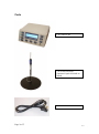
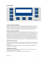
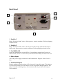
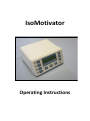
IsoMotivator
Operating Instructions
Contents
Parts................................................................................................................................ 3
Front Panel ..................................................................................................................... 4
Activate 1 Button and LED........................................................................................ 4
Activate 2 Button and LED........................................................................................ 4
Work Button and LED ............................................................................................... 4
Rest Button and LED ................................................................................................. 4
1 min Button .............................................................................................................. 5
10 sec Button.............................................................................................................. 5
1 sec Button................................................................................................................ 5
Reset Button ............................................................................................................... 5
Goal Button ................................................................................................................ 5
Sound Button ............................................................................................................ 5
Error LED .................................................................................................................. 5
Back Panel ..................................................................................................................... 6
1. Switch 1 ................................................................................................................ 6
2. Switch 2 ................................................................................................................ 6
3. On/Off Switch ....................................................................................................... 6
4. Mains Input ............................................................................................................ 6
5. Switched Output.................................................................................................... 6
Operation........................................................................................................................ 7
Start-up Settings / Information Displays........................................................................ 7
Page 2 of 7
V2.3
Parts
1 X Control Unit
2 X Switch on Stand
(Optional: Optical Switch on
Stand)
1 X Power Cable
Page 3 of 7
V2.3
Front Panel
Activate 1 Button and LED
During setup, press this button to set the amount of time the patient has to activate
switch 1. If a value has been set then the LED will light. This value also determines
the amount of time the patient has to release the switch once the work period is over.
During treatment the LED will light when the patient should activate switch 1.
Activate 2 Button and LED
During setup, press this button to set the amount of time the patient has to activate
switch 2. If a value has been set then the LED will light. If no value has been set (zero
time) then switch 2 will not be used during treatment. This value also determines the
amount of time the patient has to release the switch once the work period is over.
During treatment the LED will light when the patient should activate switch 2. If the
‘Dual Switch 2 LEDs’ setting is on (see ‘Start-up Settings / Information Displays’
section for more information) then the ‘Activate 1’ LED will light as well; this can
make it easier for the patient to see whether switch 1 or switch 2 should be activated.
Work Button and LED
During setup, press this button to set the amount of time for which the patient has to
hold the appropriate switch in an activated state. If a value has been set then the LED
will light.
During treatment the LED will light when the patient should hold the appropriate
switch in an activated state.
Rest Button and LED
During setup, press this button to set the amount of time the patient must rest after
holding a switch in the activated state.
During treatment the LED will light when the patient should rest.
Page 4 of 7
V2.3
1 min Button
Increments time by 1 minute each time pressed, or in the case of the goal setting by
100 repetitions.
10 sec Button
Increments time by 10 seconds each time pressed, or in the case of the goal setting by
10 repetitions.
1 sec Button
Increments time by 1 second each time pressed, or in the case of the goal setting by 1
repetition.
Reset Button
Resets all values to zero. If treatment is in progress then this will stop treatment.
Goal Button
During setup, press this button to set the number of repetitions the patient must
perform.
Sound Button
Switches the internal buzzer of the IsoMotivator on or off.
Error LED
If the patient fails to complete an action in the allotted amount of time then the Error
LED will light.
Page 5 of 7
V2.3
Back Panel
3
1
4
2
5
1. Switch 1
Plug a ‘Switch on Stand’ in here. (Best practice: turn the machine off before plugging
switches in/out).
2. Switch 2
Plug a ‘Switch on Stand’ in here. If only one switch is being used then this may be
left un-used. (Best practice: turn the machine off before plugging switches in/out).
3. On/Off Switch
Switch the IsoMotivator on and off here. If an appliance plugged into 5 draws too
much current, such as in a short circuit, then this switch will trip and need to be reset.
4. Mains Input
This is the power supply connector for the IsoMotivator. Plug the ‘Power Cord’ in
here.
5. Switched Output
Plug the appliance that the patient will be interested in into this output. This plug has
it’s own on/off switch, so be sure that it is in the on position during treatment. This
plug is normally on during setup / after treatment and only switches off during an
error condition.
Page 6 of 7
V2.3
Operation
1. Plug the appliance the patient will be using into the back of the IsoMotivator.
2. Plug at least one switch into the back of the IsoMotivator.
3. Plug the power cord into the wall and into the back of the unit, and switch the
unit on.
4. Set the desired treatment parameters. Please see the ‘Front Panel’ section for
more information.
5. Once enough parameters have been specified instruct the patient to activate
switch 1. As soon as switch 1 is released treatment will commence.
Tips:
Make sure that the switch on the ‘Switched Output’ plug is on. This switch
may be turned off during setup if desired.
Either one or two switches may be used. If only one is used then be sure to
plug it into the ‘Switch 1’ connector.
If the patient will be walking and pressing the switches with their hands then it
may be advisable to place the switches on an elevated surface.
Keep the switch cables out of the way of the patient, especially to prevent the
patient from tripping over them. Besides for posing an injury threat to the
patient this could damage both the control unit and the switches. If necessary
then tape the cables down.
It is best practice to turn the machine off before plugging switches in or out.
Start-up Settings / Information Displays
A number of settings / information displays are available by holding down certain
buttons when powering the unit on:
Hold ‘Activate 1’ Button: Toggle ‘Dual Switch 2 LEDs’ setting on/off (see
‘Activate 2 Button and LED’ section for more information).
Hold ‘Work’ Button: Display software version.
Page 7 of 7
V2.3