1
CROSSOVER
In a class by itself
DAWF0 and DAWS0 SERIES DRYERS
W
D R Y E R O P E R AT I N G M A N U A LX
Laundrylux
Doc. No. 112999
Rev. 47.2012
Part No. 112999 - 1
461 Doughty Boulevard
Inwood, NY 11096-0338
www.laundrylux.com
Service: (516) 371-0700
Parts: (516) 271-2000
Retain This Manual In A Safe
Place For Future Reference
Table of Contents _____________________
Please read this manual carefully to thoroughly familiarize
yourself with the Phase 5 Coin computer system features,
operational instructions, and programming characteristics.
This manual contains important information on how to use all
the features of your new dryer in the safest and fastest way.
This product embodies advanced concept s in engineering,
design, and safety. If this product is properly maint ained, it
will provide many years of safe, ef ficient, and trouble free
operation.
We have tried to make this manual as complete as possible
and hope you will find it useful. The manufacturer reserves
the right to make changes from time to time, without notice or
obligation, in prices, specifications, colors, and material, and
to change or discontinue models.
!
WARNING
Introduction ................................................ 3
L.E.D. Display and Codes ............................ 4
Operating Instructions ............................... 5
Timed Mode ..................................................................... 5
Automatic Mode (Patent No. 4,827,627) ........................ 5
Free Dry Mode ................................................................ 5
Program Selection ...................................... 6
Programming Instructions ....................... 10
Introduction To Programming ........................................ 10
Programming (Flowcharts) ............................................ 11
Programming ............................................ 14
Temperature Display Mode ........................................... 14
Left Coin Count ............................................................. 15
Right Coin Count ........................................................... 16
Program Location 01 (PL01) ......................................... 17
Program Location 02 (PL02) ......................................... 21
Program Location 03 (PL03) ......................................... 22
Program Location 04 (PL04) ......................................... 23
Program Location 05 (PL05) ......................................... 24
Program Location 06 (PL06) ......................................... 25
Program Location 07 (PL07) ......................................... 26
Program Location 08 (PL08) ......................................... 27
Program Location 09 (PL09) ......................................... 28
Program Location 10 (PL10) ......................................... 29
Program Location 11 (PL11) ......................................... 30
Program Location 12 (PL12) ......................................... 31
Program Location 13 (PL13) ......................................... 32
Program Location 14 (PL14) ......................................... 33
Program Location 15 (PL15) ......................................... 34
Program Location 16 (PL16) and
Program Location 17 (PL17) ......................................... 35
Proposition 65
Use of this product could expose you
to substances from fuel combustion that
contain chemicals known to the State of
California to cause cancer, birth defects
and other reproductive harm.
In the S tate of Massachusett s, the following inst allation
instructions apply:
■ Installations and rep airs must be performed by a
qualified or licensed contractor, plumber, or gasfitter
qualified or licensed by the State of Massachusetts.
■ If using a ball valve, it shall be a T-handle type.
■ A flexible gas connector, when used, must not exceed
3 feet.
“IMPORTANT NOTE TO PURCHASER”
Factory Preset Programs/Parameters ..... 36
Information must be obt ained from your local gas
supplier on the instructions to be followed if the user
smells gas. These instructions must be posted in a
prominent location near the dryer.
Phase 5 Coin System Diagnostics ........... 36
List of Acronyms _____________________
L.E.D.
Light Emitting Diode
PL
Program Locations
PS
Program Switch
2
Diagnostic (L.E.D.) Failure Codes ................................ 36
L.E.D. Display Indicators/Dots ...................................... 36
Phase 5 Microprocessor Controller (Computer)
Relay Output L.E.D. Indicators ..................................... 37
Phase 5 Auto Cycle (Patent No. 4,827,627)
“A” and “b” Factor Parameters ................. 37
Optional 9 Volt Battery Backup ............... 37
Laundrylux
112999 - 1
Introduction __________________________
The Phase 5 Coin Computer System is a fully programmable,
highly sophisticated dryer control system. The manufacturer
has designed the Phase 5 coin microprocessor controller
(computer) to be the most versatile and reliable coin-operated
control system available.
To eliminate as many moving p arts as possible, all Phase 5
coin microprocessor controller (computer) programming is
done through the membrane switch on the front of the control
panel. The program switch that puts microprocessor controller
(computer) into the program mode is a single program switch.
This program switch eliminates the possibility of switch failure
due to an accumulation of lint or moisture.
Phase 5 Coin Microprocessor Controller
(Computer) Features
AUTOMATIC PROGRAM REVIEW
In the program mode, the Phase 5 coin microprocessor
controller (computer) will show all settings by one touch of the
low temperature keypad selection.
PROGRAMMABLE
Changes in the programs are made at the temperature keyp
ad
selection and actual programs are displayed for verification.
ADJUSTABLE TIME
Programmable from a minimum of 1 minute to a maximum of
99 minutes in 1 minute increment s.
COIN ACCEPTOR DENOMINATIONS
Values of coin acceptors are programmable from a minimum
of 1 to a maximum value of 9999 for any U.S. or foreign coin
denomination.
AMOUNT TO START
Programmable from a minimum value of 1 to a maximum value
of 9999 in increments of one.
ACCUMULATIVE TIME
This program yields a specific value of time for any coin entry
made after the “Amount To Start” has been inserted.
Time For Amount To Start
This program retains the time the owner wishes to vend. The
feature allows any additional purchase that is made to be
calculated to the second. There is no calculation necessary
by the owner . The Phase 5 coin microprocessor controller
(computer) calculates the vended time.
BAD COIN LOCKOUT
Each coin is monitored. Should someone t amper with the
coin acceptor or attempt to insert a foreign object, the
microprocessor controller (computer) will “LOCKOUT” and will
not accept any entries until the reset time has elap sed
(approximately 15-seconds). Once the reset time has expired,
the microprocessor controller (computer) will automatically
reset itself for the next coin entry.
TEMPERATURE CONVERSION
When the temperature conversion status is changed (i.e. from
°F to °C), the Phase 5 coin microprocessor controller
(computer) will automatically convert all temperature related
programs/parameters from Fahrenheit to Celsius and vice
versa. The Phase 5 coin microprocessor controller (computer)
will perform this conversion within 1° F (2° C). The programs
affected are:
1. Temperature Display Mode
2. Temperature Selections
3. Cool Down Temperatures
DRYING TEMPERATURES
Any of the three temperature selections (HI/LO/PP) are
programmable from a minimum of 100° F to a maximum of
190° F in ten-degree increments or from a minimum of 38° C
to a maximum of 88° C in five-degree incrementt. Actual
temperature programs are displayed at time of programming
for verification. Do not program temperature above 150° F (65° C)
COOL DOWN TIME
All three temperature selections are programmable from a
minimum of 0 minutes to a maximum of 9 minutes in 1 minute
increments.
COOL DOWN TEMPERATURES
In the automatic or free dry modes, the cool down cycle
termination is programmable from a minimum of 70° F to a
maximum of 190° F in ten-degree increment s or from a
minimum of 21° C to a maximum of 88° C in five-degree
increments. Do not program temperature above 150° F (65° C)
AUTOMATIC MODE (Patent No. 4,827,627)
This program selection uses a patented Auto-Dry cycle. The
microprocessor controller (computer) will calculate the percent
of the dryness and read “donE” when complete. The Phase 5
coin microprocessor controller (computer) can be programmed
to have a maximum time for the “Auto Mode.” The Automatic
Cycle (mode) can be used in either the “Free Dry” Mode or
the “Coin” Mode.
ACCUMULATIVE COIN
This program selection requires that a specific value of coin(s)
be inserted for additional time, programmable for any minimum
amount.
COIN COUNT
The number of coins inserted, including a sep arate display
program for optional dual coin acceptors, can be viewed
through the Phase 5 computer ’s L.E.D. display.
112999 - 1
www.Laundrylux.com
3
ANTI-WRINKLE
This program selection helps keep permanent press items
wrinkle free when they are not removed from the dryer promptly
at the end of the drying and cooling cycles. The Anti-Wrinkle
program settings are:
BATTERY BACKUP (Optional)
This feature allows the Phase 5 coin microprocessor controller
(computer) to maintain its operating status should a momentary
power interruption occur while the dryer cycle is in progress.
1. Guard Delay Time .............. 1 to 9 minutes
L.E.D. Display and Codes _____________
2. Guard On Time ................... 1 to 99-seconds
3. Active Guard Time .............. 1 to 99 minutes
FREE DRY MODE
In this program selection, the dryer can be started without the
insertion of coins by simply pressing any one of the three
temperature selections. When set in the “Free Dry” Mode,
the Phase 5 coin microprocessor controller (computer) can
also be programmed to run with an Automatic Cycle (percent
of dryness) or with a Timed Cycle. If the “Free Dry” program
is utilized, the computer ’s L.E.D. display will cycle back and
forth between “FILL” to “FrEE,” unless otherwise programmed.
A
ACOn
Adrt
AFAt
AGt
AtIn
AtSt
AUtO
b
bCLO
bCrS
bUZ
°CEL
CLCC
Coin
CrCC
donE
L.E.D. FLASH DISPLAY
Programmable to allow the L.E.D. readout to display a choice
of “FILL” (no cycle in progress), “Amount To Start” (i.e., 25¢),
or, in the case of free dry, “FrEE.” This program selection also
allows the L.E.D. display to flash back and forth every
2-seconds from “FILL” to “Amount To Start” or, in the case of
free dry, from “FILL” to “FrEE.”
AUDIBLE TONE
In this program selection, a tone (buzzer) will sound for each
coin inserted, program entry, or at the drying and cooling cycles
for a period of 5-seconds to indicate that the cycle is complete.
Additionally, when in the Anti-Wrinkle program, the tone
(buzzer) will sound for 5-seconds at the end of the “Guard On
Time.”
TEMPERATURE DISPLAY
This program selection enables the temperature in the dryer
to be viewed (°F or °C) either while the dryer is off or running.
This service feature shows that the dryer is maint aining the
selected temperature.
door
dSFL
°FAr
FILL
FLS
FrEE
GdLY
Gont
Grd
HICd
Hot
LCC
LCdE
LOCd
nbUZ
nFLS
nGrd
nSEn
PdrY
PL
PLOC
PPCd
PP°F
PUSH
DIAGNOSTICS
All major circuits, including door, microprocessor temperature
sensor, heat, and motor circuit s are monitored. There are
also indicators installed on the outputs of each relay to easily
identify failures, and the door switch has an indicator installed
on the Phase 5 microprocessor controller (computer) to help
indicate failure.
AUTOMATIC DRY TIME
This program selection allows the dryer to run up to a specific
time. During the “AUtO” mode or “FrEE” dry mode this program
is only designed to limit the dryer’s operation during the drying
cycle.
ROTATIONAL SAFE GUARD (Optional)
This program monitors the rotation of the tumbler. If the tumbler
is not rot ating, the Phase 5 coin microprocessor controller
(computer) will disable all output s, an audible tone (buzzer)
will sound, and an error message will be displayed.
This
program selection can be programmed to be in the inactive
mode.
rCC
rCdE
SEFL
SEn
tFAS
tInE
Automatic Cycle (Slope Program Factor)
Accumulative Coin
Maximum Auto Dryness Time
Amount for Additional Time
Active Anti-Wrinkle Guard Time
Accumulative Time
Amount To Start
Automatic Mode (Patent No. 4,827,627)
Automatic Cycle (Heat Loss [of fset] Factor)
Bad Coin Lockout
Bad Coin Reset
Buzzer (Tone)
Degree in Celsius
Clear Left Coin Count
Coin Mode
Clear Right Coin Count
Drying and Cooling Cycles Complete
or
Dryer is in Anti-Wrinkle Cycle
Door Circuit is Open*
Dryer Sensor Circuit Failure*
Degree in Fahrenheit
No Cycle in Progress
Flash Display Active
Free Dry Mode
Anti-Wrinkle Delay Time
Anti-Wrinkle On Time
Anti-Wrinkle Program Active
High Cool Down
Overheating Condition*
Left Coin Count
Left Coin Denomination
Low Cool Down
No Buzzer (Tone)
No Flash Display
No Anti-Wrinkle
No Rotational Sensor Selected
Percent Dry
Program Location
Program Location Automation Review
Permanent Press Cool Down
Permanent Press
Amount to start has been Inserted
Make Temperature Selection
Right Coin Count
Right Coin Denomination
Rotational Sensor Circuit Failure*
Rotational Sensor Selected
Time For Amount to Start
Timed Mode
* Refer to Phase 5 Coin System Diagnostics on apge 36 for detailed information.
4
Laundrylux
112999 - 1
Operating Instructions _______________
NOTE: Unless otherwise specified at the time of ordering,
the Phase 5 coin microprocessor controller (computer) has
been preprogrammed by the factory with the parameters
shown on page 36. Should program changes be found
necessary, please read this Phase 5 Coin User’s Manual
carefully to thoroughly familiarize yourself with the Phase 5
coin microprocessor controller (computer) programming
characteristics.
Timed Mode ___________________________
When turning on power or when no cycle is in progress, the
L.E.D. display will read “FILL” and/or “Amount To Start” (“AtSt”).
Insert coin(s). Once the correct “Amount To Start” has been
inserted, the L.E.D. display will read “PUSH.”
Select temperature by pushing “HI TEMP,” “LO TEMP,” or
“PERM PRESS.” The dryer will start and the L.E.D. display
will read the temperature cycle selected and the drying time.
The dryer will continue through the drying and cooling cycles,
showing time counting downward.
NOTE: If the door is opened during a cycle, both the heat
and motor will stop. However, the Phase 5 coin
microprocessor controller (computer) will continue to count
downwards in time. Continuation of the cycle will resume
only after the door has been closed and any one of the
three temperature selection buttons is again depressed.
Upon completion of the drying and cooling cycles, the buzzer
(tone) will sound, and the L.E.D. display will read “donE” for
5-seconds, at which time the dryer will shut off.
NOTE: If the Anti-Wrinkle Program is active (“Grd”), the
L.E.D. display will remain reading “donE,” and the Phase 5
coin microprocessor (computer) will proceed through the
Anti-Wrinkle Program until the maximum “Guard On Time”
has expired or until the door is opened, whichever comes
first. The L.E.D. display will read “FILL” and/or “Amount To
Start” (“AtSt”).
If the Anti-Wrinkle Program is not active (“nGrd”) the L.E.D.
display will read “donE” until the main door is opened, at
which time the L.E.D. display will read “FILL” and/or
“Amount To Start.”
Automatic Mode
(Patent No. 4,827,627) ________________
When turning on power or when no cycle is in progress, the
L.E.D. display will read “Fill” and/or “AmountTo Start” (“AtSt”).
Insert coin(s). Once correct “Amount to S tart” has been
inserted, the L.E.D. display will read “PUSH.”
Select temperature by pushing “HI TEMP,” “LO TEMP,” or
“PERM PRESS.” The dryer will start, the L.E.D. display will
read the temperature cycle selected, and the drying time
portion of the L.E.D. display will display the time and count
down as time elapses.
112999 - 1
NOTE: If the door is opened during a cycle, both the heat
and motor will stop. However, the Phase 5 coin
microprocessor controller (computer) will continue to count
downwards in time. Continuation of the cycle will resume
only after the door has been closed and any one of the
three temperature selection buttons is again depressed.
Once the preprogrammed dryness level and cool down period
have been reached or maximum automatic time has expired,
whichever comes first, the buzzer (tone) will sound, and the
L.E.D. display will read “donE” for 5-seconds, at which time
the dryer will shut off.
NOTE: If the Anti-Wrinkle Program is active (“Grd”), the
L.E.D. display will remain reading “donE,” and the Phase 5
coin microprocessor controller (computer) will proceed
through the Anti-Wrinkle Program until the maximum
“Guard On Time” has expired or door is opened, whichever
comes first. The L.E.D. will read “FILL” and/or “Amount To
Start” (“AtSt”).
If the Anti-Wrinkle Program is not active (“nGrd”), the
L.E.D. display will read “donE” until the main door is
opened, at which time the L.E.D. display will read “FILL”
and/or “Amount To Start.”
Free Dry Mode ________________________
When turning on power or when no cycle is in progress, the
L.E.D. display will read “FILL” and/or “FrEE.”
Select temperature. The dryer will st art, the L.E.D. display
will read the temperature cycle selected and the drying time
portion of the L.E.D. display will read the temperature cycle
selected. The drying time portion of the L.E.D. drying will read
“00” and count upward as time elap ses, or the vended time
will count downward, depending on which p arameter is
programmed.
NOTE: If the door is opened during a cycle, both the heat
and motor will stop. However, the Phase 5 coin
microprocessor controller (computer) will continue to count
the time, either upward or downward, depending on which
parameter is programmed. Continuation of the cycle will
resume only after the door has been closed and any one of
three temperature selection buttons is again depressed.
Once the preprogrammed percent dryness level and cool down
period has been reached or maximum automatic time has
expired, whichever comes first, the tone (buzzer) will sound,
and the L.E.D. display will read “donE” for 5-seconds, at which
time the dryer will shut off.
NOTE: If the Anti-Wrinkle Program is active (“Grd”), the
L.E.D. display will remain reading “donE,” and the Phase 5
coin microprocessor controller (computer) will proceed
through the Anti-Wrinkle Program until the maximum
“Guard On Time” has expired or door is opened, whichever
comes first. The L.E.D. display will read “FILL” and/or
“Amount To Start” (“AtSt”).
If the Anti-Wrinkle Program is not active (“nGrd”), the
L.E.D. display will read “donE” until the main door is
opened, at which time the L.E.D. display will read “FILL”
and/or “Amount To Start.”
www.Laundrylux.com
5
Program Selection ____________________
NOTE: Programs are stored in the Phase 5 coin
microprocessor controller (computer) memory and are
cataloged as PL.
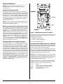
Temperature Display Mode
By closing the PS located on the back side of the Phase 5
coin microprocessor controller (computer), the L.E.D. display
will read the temperature in the dryer in either Fahrenheit (°F)
or Celsius (°C), depending on how the temperature conversion
status is in PL01. The temperature display mode can be
activated while the dryer is in the operating cycle, or of
f. While
in the operating cycle, the circuit indicators are visible for
troubleshooting purposes.
NOTE: The dryer cannot be started while the Phase 5 coin
microprocessor controller (computer) PS is closed, unless
the cycle was already in progress.
Right Coin Count (rCC)/Left Coin Count (LCC)
The “HI TEMP” key lets the operator review the coin counters.
If the operator presses the “HI TEMP” key, the computer
displays “_LCC.” The operator could then press either the
“PERM PRESS” key to view the “Lef t Coin Count” or the “HI
TEMP” key and the computer would display “_rCC.” Again,
the operator could press the “PERM PRESS” key to view the
“right coin count.” While displaying the coin count, if the
operator presses the “HI TEMP” key the computer then
displays “CxCC” (x = “r” or “L”) to indicate “clearing” the coin
count. The operator then presses the “PERM PRESS” key to
clear the coin count or the “HI TEMP” or “LO TEMP” key to
exit without clearing the coin count.
PL01 – Temperature Conversion Status
This program controls whether the temperature related
programs will be operated in Fahrenheit (°F) or Celsius (°C).
The programs affected are:
1. Temperature Display Mode
2. Selection Cycling Temperatures
Automatic Review of Program Location
3. Cool Down Temperatures
This selection allows for the AUTOMATIC REVIEW of what
the program locations are set (programmed) for , thereby
eliminating the need to go into each and every PL manually
for verification. By closing the PS with no cycle in progress,
the L.E.D. display will read the temperature in the dryer
. Then,
by pressing the “LO TEMP” key, the L.E.D. display will read
“PLOC” for 1-second. Then, the Phase 5 coin microprocessor
controller (computer) will go into theAutomatic Review Mode,
the Program Location numbers (i.e., PL01, PL02, etc.) will not
be shown and each parameter (i.e., “°FAr,” “tInE,” “Grd,” etc.)
will be displayed for approximately 1-second each.
The
Automatic Review can be stopped/exited at any time by simply
pressing the “PERM PRESS” key , at which time the L.E.D.
display will read “0000” for 1-second and then return to the
Temperature display mode.
Automatic Mode (AUtO) Patent No. 4,827,627
When this p arameter (“AUtO”) is selected, the dryer will run
for a preset level of dryness (PL02) or until the programmed
automatic maximum time (PL14) has expired.
At the end of the drying cycle, the dryer will go into the cool
down cycle for the time period programmed (PL04, PL06, or
PL08) or until the temperature has dropped to the programmed
cool down temperature (PL04, PL06, or PL08).
NOTE: Due to humidity, atmospheric pressure, percentage
of extraction, etc., the desired dryness level may vary. It is
suggested that the owner determine which level of dryness
(90% to 100%) is best suited for his/her application by
experimenting with a few test loads.
When programming, to use the Automatic Mode (“AUtO”)
(Patent No. 4,827,627), the following parameter/programs
need to be checked and/or changed accordingly:
PL01 .......... “AUtO”
“FrEE” or “Coin” (coins required to start)
PL02 .......... “PdrY” (percent dry from 90% to 100%)
PL14 .......... “Adrt” (maximum auto dry time)
PL17 .......... “A” and “b” Factors
6
Laundrylux
112999 - 1
Timed Mode (tInE)
When this parameter is selected (“tInE”) and the Phase 5 coin
microprocessor controller (computer) has been activated, the
dryer will continue to run until the preset time, including the
cool down period (PL04, PL06, or PL08), has elap
sed, at which
time the dryer will cycle off or go into the optionalAnti-Wrinkle
Program.
Anti-Wrinkle Program (Grd)
This feature can be used in conjunction with any of the three
operating modes (Coin Mode, Auto Mode, or the Free Dry
Mode). In this program (“Grd”), when the drying and cooling
cycles are completed, the dryer will shut off, the buzzer (tone)
will sound, and the L.E.D. display will read “donE.” If the door
is not opened, the Phase 5 coin microprocessor controller
(computer) will wait until the “Guard Delay Time” (PL15) has
expired, at which time the clothes will be tumbled (without
heat) for the programmed ”Guard On Time” (PL15). The Phase
5 coin microprocessor controller (computer) will repeat this
process until the programmed “Active GuardTime” (PL16) has
expired or until the dryer door is opened, at which time the
L.E.D. display will read “FILL” and/or “AmountTo Start” (“AtSt”)
or “FILL” and/or “FrEE.”
NOTE: When programming the use of the Anti-Wrinkle
Program (“Grd”), the following parameter/programs need to
be checked and/or changed accordingly:
PL01 ........ “Grd” (Anti-Wrinkle Program active)
“bUZ” or “nbUZ” (buzzer [tone] active/not active)
PL15 ........ “GdLY” (guard delay time)
“Gont” (guard on time)
PL16 ........ “AGt” (active guard time)
Buzz/Tone (bUZ)
With the Anti-Wrinkle Program active, the option is available
to have the buzzer/tone (“bUZ”) sound for a period of
5-seconds at the end of each “Guard On Time” cycle, or, no
buzzer (“nbUZ”) sound.
Free Dry Mode (FrEE)
The Phase 5 coin microprocessor controller (computer) can
be programmed to run without the insertion of coins. When
the Phase 5 coin microprocessor controller (computer) is in
the “FrEE” dry mode, it may be programmed to run in the
“AUtO” (Automatic) Mode or the “tInE” (Timed) Mode.
NOTE: When programming the use of the Free Dry Mode
(“FrEE”), the following parameters/programs need to be
checked and/or changed accordingly:
PL01 ........ “AUtO” (automatic drying cycle) or
“tInE” (timed drying cycle) “FrEE”
PL02* ...... “PdrY” (percent dry)
PL14* ...... “Adrt” (maximum auto dry time)
PL17* ...... “A” and “b” factors
NOTE: When programming the use of the Coin Mode,
(“Coin”), the following parameter/programs need to be
checked and/or changed accordingly:
PL01 ........ “AUtO” (automatic drying cycle) or
“tInE” (timed drying cycle) “FrEE”
PL02* ...... “PdrY” (percent dry)
PL11 ........ “tFAS” (time for amount to start)
PL12 ........ “AtSt” (amount to start)
PL14* ...... “Adrt” (maximum auto dry time)
PL17* ...... “A” and “b” factors
* Needs to be programmed only if PL01 “AUtO” cycle is chosen.
Flash Display Status (FLS)
When the Phase 5 coin microprocessor controller (computer)
is set in this program status (“FLS”) it allows the L.E.D. readout
to display “FILL” and/or “FrEE” (no cycle in progress), and/or
“Amount To Start” (PL12) or, in the case of free dry , “FrEE.”
The programming allows the L.E.D. readout to flip-flop back
and forth every 2-seconds from “FILL” to “Amount to Start,” or
in the case of free dry , from “FILL” to “FrEE.” If the L.E.D.
display is programmed for “No Flash” (“nFLS”), the
microprocessor controller (computer) will then prompt you on
whether you would like “FILL” displayed or the “Amount To
Start” (“AtSt”).
Bad Coin Lockout Status (bCLO)
In this program status (“bCLO”), each coin entry is monitored.
Should someone tamper with the coin acceptor or attempt to
insert a foreign object, the Phase 5 coin microprocessor
controller (computer) will “LOCKOUT” and not accept any
entries until the reset time has elap sed (approximately
15-seconds). Once the reset time has expired, the Phase 5
coin microprocessor controller (computer) will automatically
reset itself immediately for the next entry.
Bad Coin Reset (bCrS)
When set in this program (“bCrS”), the Phase 5 coin
microprocessor controller (computer) count s in milliseconds
the amount of time required for a coin entry signal. If someone
should tamper with the coin acceptor or attempt to insert a
foreign object, the Phase 5 coin microprocessor controller
(computer) will not accept the entry and will automatically reset
itself immediately for the next entry.
Accumulative Time (AtIn)
(Single Coin)
In this program mode (“AtIn”), each coin inserted has a specific
value in time, which is determined by the “Time For Amount to
Start” (“tFAS”) program (PL11).
Example No. 1: If the dryer is equipped with a 25¢ coin acceptor
and the desired time is 30 minutes, each additional coin
inserted would yield 30 minutes.
Settings: PL09 (LCdE) ...................... 25
PL11 (tFAS) ........................ 30
PL12 (AtSt) ........................ 25
* Needs to be programmed only if PL01 “AUtO” cycle is chosen.
Coin Mode (Coin)
In this program mode (“Coin”), coins are required to st art the
dryer, even if the Phase 5 coin microprocessor controller
(computer) is set in the Automatic Mode (Patent No.
4,827,627).
112999 - 1
Example No. 2: If the dryer is equipped with a 25¢ coin acceptor
and the “Amount To Start” (“AtSt”) is 50¢ for 30 minutes, the
insertion of each additional coin would yield 15 minutes. In
this application the vended time for additional coins is
determined by a Phase 5 coin microprocessor controller
(computer) calculation. There is no calculation required by
the owner.
www.Laundrylux.com
7
Formula: (LCdE/AtSt) (tFAS) = Vended Time for “ LCdE”
(25¢/50¢) (30) = 15 minutes
Settings: PL09 (LCdE) ...................... 25
PL11 (tFAS) ........................ 30
PL12 (AtSt) ........................ 50
(Dual Coin)
In the Accumulative Time (AtIn) Mode, when using a dual coin
acceptor, once the “AmountTo Start” (“AtSt”) has been inserted,
the addition of a coin(s) yields more time.
The vended time for additional coins is determined by the
Phase 5 coin microprocessor controller (computer) calculation.
There is no calculation required by the owner.
Formula: (LCdE/AtSt) (tFAS) = Vended Time
Example No. 1: Using a 10¢/25¢ dual coin acceptor with the
desired “Amount to S tart” (“AtSt”) being 25¢ for 15 minutes,
each additional 10¢ would yield the following:
Formula: (LCdE/AtSt) (tFAS) = Vended Time for “LCdE”
(10¢/25¢) (15 minutes) 6 minutes
Accumulative Coin (ACOn)
When this program mode (“ACOn”) is selected, additional time
can only be achieved when the “Amount For Additional Time”
(“AFAt”) PL13 has been inserted.
NOTE: When programming, to use the Accumulative Coin
Mode (“ACOn”), the following parameters/programs need
to be checked and/or changed accordingly:
Settings: PL01 ......................... “ACOn”
(“Accumulative Coin”)
PL13 ........................... “AFAt”
(“Amount For Additional Time”)
(Single Coin Acceptor)
Example No. 1: Using a 25¢ coin acceptor with the desired
“Amount To Start” (“AtSt”) being 50¢ for 24 minutes, the Phase
5 coin microprocessor controller (computer) would yield more
time (24 minutes) only when an additional 50¢ is inserted.
For this application, the “T ime For Amount To Start” (“tFAS”)
program (PL11) is determined as follows:
Formula: (AFAt/AtSt) (tFAS) = Vended Time for “AFAt”
(50¢/50¢) (24 minutes) = 24 minutes
Settings: PL09 (LCdE) ...................... 10
PL10 (rCdE) ....................... 25
PL11 (tFAS) ........................ 15
PL12 (AtSt) ........................ 25
Example No. 2: If the dryer is equipped with a 10¢/25¢ dual
coin acceptor and the desired “Amount To Start” (“AtSt”) is
35¢ for 14 minutes, each additional 10¢ inserted would yield
4 minutes and each additional 25¢ would yield 10 minutes.
Settings: PL09 (LCdE) ...................... 25
PL11 (tFAS) ........................ 24
PL12 (AtSt) ........................ 50
PL13 (AFAt) ....................... 50
(Dual Coin Acceptor)
With a dual coin acceptor the “T ime For Amount To S tart”
(“tFAS”) is determined as shown below:
Formula: (LCdE/AtSt) (tFAS) = Vended Time for “LCdE”
(10¢/35¢) (14 minutes) 4 minutes
Formula: (AFAt/AtSt) (tFAS) = Vended Time for “AFAt”
Settings: PL09 (LCdE) ...................... 10
PL10 (rCdE) ....................... 25
PL11 (tFAS) ........................ 14
PL12 (AtSt) ........................ 35
Example No. 3: If the dryer is equipped with a 10¢/25¢ dual
coin acceptor and the desired “Amount To Start” (“AtSt”) is
55¢ for 33 minutes, each additional 10¢ inserted would yield
6 minutes, and each additional 25¢ would yield 15 minutes.
Example No. 1: Using a 10¢/25¢ dual coin acceptor the desired
“Amount To Start” (“AtS t”) is 50¢ for 20 minutes and the
“Amount for Additional Time” (“AFAt”) is set for 20¢ each
additional 20¢ would yield 8 minutes.
Formula: (AFAt/AtSt) (tFAS) = Additional Vended Time
(20/50) (20 minutes) = 8 minutes
Settings: PL09 (LCdE) ...................... 10
PL10 (rCdE) ....................... 25
PL11 (tFAS) ........................ 20
PL12 (AtSt) ........................ 50
PL13 (AFAt) ....................... 20
Formula: (LCdE/AtSt) (tFAS) = Vended Time for “LCdE”
(10¢/55¢) (33 minutes) 6 minutes
Settings: PL09 (LCdE) ...................... 10
PL10 (rCdE) ....................... 25
PL11 (tFAS) ........................ 33
PL12 (AtSt) ........................ 55
NOTE: If the total Vend Time cannot be divided evenly by
the “Amount To Start” (“AtSt”), the “Time For Amount To
Start” will calculate precisely the amount of the time
entitled to the purchaser.
Example No. 2: If the dryer is equipped with a 10¢/25¢ dual
coin acceptor and the desired “Amount To Start” (“AtSt”) is
35¢ for 14 minutes and the “Amount For Additional Time”
(“AFAt”) is set for 25¢, each additional 25¢ inserted would
yield 10 minutes.
Formula: (LCdE/AtSt) (tFAS) = Vended Time for “LCdE”
(10¢/35¢) = 2.85 minutes
(2 minutes and 51-seconds)
Settings: PL09 (LCdE) ...................... 10
PL10 (rCdE) ....................... 25
PL11 (tFAS) ........................ 14
PL12 (AtSt) ........................ 35
PL13 (AFAt) ....................... 25
Settings: PL09 (LCdE) ...................... 10
PL10 (rCdE) ....................... 25
PL11 (tFAS) ........................ 10
PL12 (AtSt) ........................ 35
8
Formula: (AFAt/AtSt)(tFAS) = Vended Time for “AFAt”
(25¢/35¢) (14 minutes) = 10 minutes
Laundrylux
112999 - 1
Rotational Safe Guard – Optional (nSEn)
PL05 – Low Temperature (LO°F)
This program monitors the rot ation of the tumbler and works
in conjunction with a special sensor (optional) located at the
rear tumbler support area of the dryer . If the tumbler is not
rotating (i.e., broken belt, failed motor , etc.), the Phase 5
microprocessor controller (computer) will disable all output s
(shut the dryer down), the buzzer (tone) will sound (for time
programmed), and the L.E.D. display will read a failure
message “SEFL” (Rot ational Sensor Circuit Failure). The
failure code must be cancelled manually by opening and
closing the PS. This program selection (option) can be
programmed to be active (“SEn”) or inactive (“nSEn”).
Same as PL03 but for Low Temperature program.
NOTE: This parameter is programmed by the factory to be
inactive (“nSEn”) unless the dryer was manufactured with
optional “rotational sensor.”
Same as PL04 but for Permanent Press Cool Down
Temperature/Time.
PL06 – Low Cool Down
Temperature/Time (LOCd)
Same as for PL04 but for low Cool Down Temperature/Time.
PL07 – Permanent Press (PP°F)
Same as PL03 but for Permanent Press.
PL08 – Permanent Press Cool Down
Temperature/Time (PPCd)
PL09 – Left Coin Slot Denomination (LCdE)
PL02 – Percent Dry (PdrY)
When in theAutomatic Mode, the dryer will run until the preset
level of dryness has been reached or until the MaximumAuto
Dryness Time (Adrt) has been reached or until the Maximum
Auto Dryness Time (Adrt) has expired. The dryness level is
programmable from a minimum of 90% to a maximum of 100%.
NOTE: Due to humidity, atmospheric pressure, water
retention in the garment etc., the desired “Percent Dry”
(“PdrY”) may vary. It is suggested that the owner
determine which level of dryness (90% to 100%) is best
suited for his/her application by experimenting with a few
test loads.
PL03 – High Temperature (HI°F)
The high operating temperature is programmable from a
minimum of 100° F to a maximum of 190° F in ten-degree
increments or from a minimum of 38° C to a maximum of 88°
C in five-degree increments.
PL04 – High Cool Down
Temperature/Time (HICd)
In the case of a single coin acceptor , this program setting is
determined by the value of the coin acceptor (i.e., 25¢).
When a dual coin acceptor is used, the program setting is
determined by the lef t coin slot coin acceptor value (lower
coin value).
Program settings are from a minimum of 1 to a maximum of
9999.
PL10 – Right Coin Slot Denomination (rCdE)
This program need only be set when a dual coin acceptor is
used. The program setting is determined by the value of the
right coin acceptor slot (higher value).
Program settings are from a minimum of 1 to a maximum of
9999.
When used in conjunction with the left Coin Slot Denomination
program, the Phase 5 microprocessor controller (computer)
automatically calculates the ratios necessary for coin insertion
time values.
PL11 – Time For Amount To Start (tFAS)
The first p art of this program controls the cool down
temperature when the Phase 5 microprocessor controller
(computer) is used in the automatic mode. The cool down
temperature is programmable from a minimum of 70° F to a
maximum of 190° F in ten-degree increment s or from a
minimum of 21° C to a maximum of 88° C in five-degree
increments.
This program is set for the specific value in TIME that will be
vended for the programmed “Amount To Start” (“AtSt”) the
dryer. For example, if 25¢ is required to start the dryer for 10
minutes, the settings would be...
The second part of this program controls the cool down time
for both the automatic and timed modes. The cool down time
can be programmed from a minimum of 0 to a maximum of 9
minutes.
In addition, with the “T ime For Amount to Start” (“tFAS”) and
the “Amount To Start” (PL12 – “AtSt”) programmed along with
the type of coin acceptor (denominations) on the dryer (i.e.
10¢/25¢), the Phase 5 microprocessor controller (computer)
will do all calculations and vend the correct amount of time for
any coin inserted after the initial “Amount To Start” has been
inserted – including both accumulative coin program settings.
For example, if a dryer is equipped with a 10¢/25¢ dual coin
acceptor and the desired “Amount To Start” (“AtSt”) is 55¢ for
33 minutes (“tF AS”), with the microprocessor controller
(computer) set for accumulative time, after initial “Amount To
Start” is inserted (55¢), each additional 10¢ inserted would
yield 6 minutes, and each additional 25¢ inserted would yield
15 minutes.
NOTE: When the Phase 5 microprocessor controller
(computer) is used in the automatic mode, at the end of the
drying cycle, the Phase 5 microprocessor controller
(computer) will start the cooling cycle for the cool down
time programmed or until the temperature has dropped to
the programmed cool down temperature, whichever of the
two comes first.
112999 - 1
PL11 “Time for Amount to Start” .............. “tFAS” = 10
PL12 “Amount To Start” ............................ “AtSt” = 25
www.Laundrylux.com
9
PL12 – Amount To Start (AtSt)
Programming Instructions ___________
This program sets the “Amount To Start” the dryer and can be
programmed from a minimum of 1 to a maximum of 9999.
Introduction To Programming
PL13 – Minimum Amount
For Additional Time (AFAt)
This program need only be set when the Phase 5
microprocessor controller (computer) is set in the
“Accumulative Coin” (“ACOn”) mode (PL01). The value set
for this program is what will have to be inserted for more time
after the “Amount To Start” (“AtSt”) has been inserted.
Example No. 1: “Amount to Start” (“AtSt”) is 50¢ for 30 minutes
and an additional 50¢ is required for more time. In this example
PL13 should be set for 50¢.
PL14 – Maximum Time
For Automatic Dry (Adrt)
This program is used only when the Phase 5 microprocessor
controller (computer) is set in the Automatic Mode. This
program controls the maximum time the dryer will run even if
the Dryness Level program (PL02) has not been reached.
PL15 – Anti-Wrinkle Timing
Guard Delay Time (GdLY)
This program controls the dwell (stop) time and activation of
anti-wrinkle “Guard On Time” (“Gont”). The dwell (stop) time
can be programmed from a minimum of 1 minute to a maximum
of 9 minutes in 1 minute increment s.
Guard On Time (Gont)
The setting controls the amount of time that the tumbler will
turn, without heat, when theAnti-Wrinkle is active (“Grd”). The
“Guard On Time” (“Gont”) is programmable from a minimum
of 1-second to a maximum of 99-seconds in 1-second
increments.
The various program (parameters) dryer selections are stored
in the computer memory and are cataloged as “PL” 1 through
17. These programs (parameters) have been preprogrammed
by the factory as noted on page 36 of this manual. The various
program selections available are outlined in the proceeding
section (Program Selection on page 6).
All programming is done through the keypad selection buttons
on the front of the control p anel. To change programs
(parameters) or to put the Phase 5 microprocessor controller
(computer) in the temperature display mode or the coin count
display mode, the PS located on the back side of the
microprocessor controller (computer) must be put into the
(down) position (PSC). Note: on DA WS0 dryers with the
controls on the bottom, the lint door sensor switch must be
temporarily pushed in while flipping the PS toggle switch down.
Failure to do so will prevent the controller from entering into
programming mode.
First make sure there is no cycle in progress and the L.E.D.
display reads “FILL” and/or “Amount To Start,” or “FILL” and/
or “FrEE.” Close the Program Switch (PSC).
The L.E.D.
display will now read the temperature in the dryer (i.e., 72° F
[22° C]). From this point, any of the 17 program locations can
be accessed by pressing the “PERM PRESS” key once, at
which time the L.E.D. display will read “PL01.”
To alter programming, the operator must first locate the
program location or parameter to be changed. To advance to
the specific program location press the “HI TEMP” key until
the desired program location is displayed (i.e. PL01, PL02,
etc.). The “LO TEMP” key will advance the program locations
downward (i.e., PL11, PL10, etc.). Once the correct program
location is displayed and access to change is desired, press
the “PERM PRESS” key. The “PERM PRESS” key provides
two functions:
Allows access into a PL.
PL16 – Active Guard Time (AGt)
This program controls the maximum time that theAnti-Wrinkle
Program will be active and is programmable from a minimum
of 1 minute to a maximum of 99 minutes in 1 minute
increments.
PL17 – “A” and “b” Factors
This location will include the “Auto-Cycle” parameters. These
parameters are necessary to allow the Phase 5 microprocessor
controller (computer) to calculate the percent age of dryness
in the tumbler. The “A” Factor is adjustable from 1 to 99.
Advances to next bit (p art of a program location) or next
location.
NOTE: When in a PL and the “PERM PRESS” key is
pressed, whatever parameter is displayed will be stored in
the microprocessor controller’s (computer’s) memory and
the programming is now advanced to the next step (bit) or
program location.
These p arameters are the factors that the Phase 5
microprocessor controller (computer) utilizes when
programmed for an “Automatic Drying Cycle.” The “A” Factor
slope program, pertains to the thermal characteristic of each
model dryer. The “b” Factor, heat loss (offset) program, also
pertains to the thermal characteristics of each model dryer .
This factor setting is dependent upon the model dryer and
type of heating unit.
The “A” and “b” Factors have not been preprogrammed by
the factory and must be programmed if the Phase 5
microprocessor controller (computer) programming is changed
to be used in the Automatic Mode. The “A” and “b” Factors
must be programmed for the particular dryer model and heating
unit as shown in the “A” and “b” Factors (parameter) table on
page 37 of this manual.
10
Laundrylux
112999 - 1
The “HI TEMP” or “LO TEMP” key provide the following
functions:
Change numeric values...“HITEMP” increases and “LO TEMP”
decreases.
Notes _______________________________________________________
Flip-flop for status changes...by pressing either key, a status
will revert back and forth no matter which of the two keys is
pressed.
____________________________________________________________
If the change to be made is a numerical one (i.e., time or
temperature), the operator must now press the “HI TEMP”
key to increase the number value, or press the “LO TEMP”
key to lower/increase the number value. Pressing the “PERM
PRESS” key will store the change and advance to the next
step (bit) or program location.
____________________________________________________________
NOTE: To accelerate increase/upward value, press and
hold in “HI TEMP” key. To accelerate decrease/downward
value, press and hold in “LO TEMP” key.
When making numerical changes, please keep in mind to
stay within the programming limits shown.
If the change to be made is a st atus change (i.e., to change
from °FAr to °CEL) simply press the “HITEMP” or “LO TEMP”
key and the L.E.D. display will revert back and forth between
status choices (i.e. “Grd” and “nGrd”). Once the correct st
atus
is displayed, pressing the “PERM PRESS” key will store the
change and advance to the next step (bit) or program location.
Once the change or changes desired are made, to exit program
mode flip up (open) the PS.
NOTE: You can exit the programming mode at any time
(even if you are in the middle of a program location) by
simply opening the PS. However, if a change was made
be sure the “PERM PRESS” key is pressed before opening
the PS to ensure the change was stored in the
microprocessor controller’s (computer’s) memory.
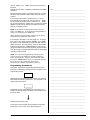
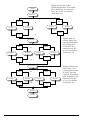
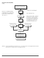
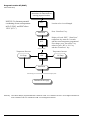
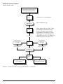
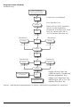
Programming (Flowcharts)
This section explains the programming through the use of
flowcharts. A flowchart is nothing more than a diagram of the
programming process.
____________________________________________________________
____________________________________________________________
____________________________________________________________
____________________________________________________________
____________________________________________________________
____________________________________________________________
____________________________________________________________
____________________________________________________________
____________________________________________________________
____________________________________________________________
____________________________________________________________
____________________________________________________________
____________________________________________________________
____________________________________________________________
____________________________________________________________
____________________________________________________________
____________________________________________________________
____________________________________________________________
____________________________________________________________
Represents the microprocessor L.E.D. display. For example,
if the flowchart shows the symbol “FILL,” the computer L.E.D.
display will read the same.
____________________________________________________________
____________________________________________________________
____________________________________________________________
Represents the key on the label that is to be pressed. For
example, if flowchart shows “HI TEMP,” you would press that
key on the label.
____________________________________________________________
➞
____________________________________________________________
____________________________________________________________
____________________________________________________________
Represents the program path.
____________________________________________________________
On the side of each flowchart is an explanation of the chart
procedures, in some cases, the programming limit s.
____________________________________________________________
____________________________________________________________
____________________________________________________________
112999 - 1
www.Laundrylux.com
11
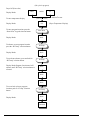
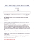
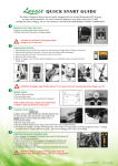
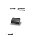
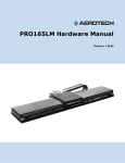
(No cycle in progress)
Dryer Off (Power On)
Display Reads
FILL
To enter temperature display
Display Reads
To enter program locations press the
“Perm Press” keypad selection button.
Display Reads
To advance to next program location
press the “HI Temp” selection button.
Display Reads
To accelerate advance, press and hold in
“HI Temp” selection button.
Display Reads Program Location and will
advance until “HI Temp” selection button is
released.
and/or
(Close Program Switch)
75F
25
Amount To start
(Dryer Temperature Display)
Perm Press
PL01
HI Temp
PL02
HI Temp
PL03
PL04
PL05
To revert back to lower program
locations push “LO Temp” selection
button.
Display Reads
LO Temp
PL04
Continued
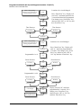
12
American Dryer Corp.
112146 - 61
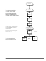
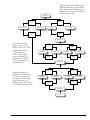
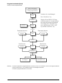
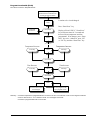
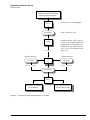
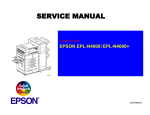
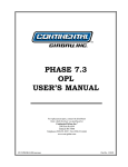
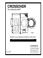
Continued
LO Temp
To accelerate press and hold in
“LO Temp” selection button.
Display reads program locations
and will advance downward until
“LO Temp” selection button is released.
PL03
PL02
PL01
To enter a specific program location
(i.e. PL01) push the “Perm Press”
selection button.
Perm Press
Display will read specific program
location called up.
To exit program mode, open
program switch. Display reads.
112146 - 61
°FAr
FILL
www.amdry.com
and/or
(Example)
25
13
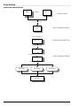
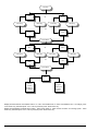
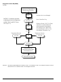
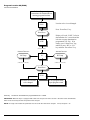
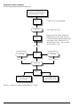
Programming ______________________________________________________________________
Temperature Display Mode
FILL
and/or
25
(Amount To Start)
(Close Program Switch)
75F
(Dryer Temperature Display)
Cycle In Progress
HI°2°0
(Temperature Selection/Time)
(Close Program Switch)
13°5°F
(Open Tumbler Door – Dryer Shuts Off)
135F
(Dryer Temperature Display)
(Close Door – Open Program Switch)
HI Temp
LO Temp
Perm Press
LO°2°0
14
American Dryer Corp.
112146 - 61
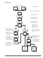
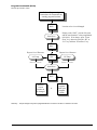
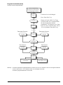
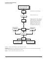
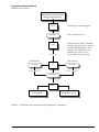
Left Coin Count
(No Cycle in Progress)
(Amount To Start)
and/or
FILL
25
(Dryer Temperature Display)
(Close Program Switch)
70F
Press “HI Temp” key.
HI Temp
Display will read “LCC”
(left coin count).
LCC
Press “Perm Press” key
to display coin count.
Perm Press
0126
To cancel or delete
left coin count, press
“HI Temp” key.
Display will read
“CLCC” (cancel left
coin count).
Press “Perm Press”
key and display
will read “0000”
(coin count cancelled).
Press “Perm Press”
key and display
will read “rCC”
(right coin count).
112146 - 61
To cancel coin count
To retain coin count
HI Temp
Perm Press
CLCC
rCC
Display will read
actual coin count.
I.E. 0126 = 126 units
or coins.
To retain or save existing
coin count press “Perm
Press.”
To Exit
Perm Press
0000
HI Temp
Display will read “rCC”
(right coin count). To exit
press “HI Temp.”
0000
Display will read “0000”
for 1-second and then
dryer temperature display.
Perm Press
70F
To review
rCC proceed
to flowchart
Right Coin
Count
www.amdry.com
To exit
program
mode open
program
switch
15
Right Coin Count
(No Cycle In Progress)
and/or
FILL
25
(Amount To Start)
(Close Program Switch)
HI Temp
(Dryer Temperature Display)
70F
LCC
Press “HI Temp” key.
Display will read “LCC”
(left coin count).
HI Temp
Press “HI Temp” key.
Display will read “rCC”
(right coin count).
rCC
Press “Perm Press” key to
display coin count.
Perm Press
0192
To cancel coin count
To cancel or delete
right coin count,
press “HI Temp” key.
Display will read
“CrCC (cancel right
coin count).
HI Temp
CrCC
Press “Perm Press”
key and display
will read “0000”
(coin count cancelled).
Perm Press
Press “Perm Press”
key.
Perm Press
To retain coin count
Perm Press
0000
Display will read
actual coin count.
I.E. 0192 = 192 units
or coins.
To retain or save
existing coin count
press “Perm Press.”
Display will read “0000”
for 1-second and then dryer
temperature display.
70F
0000
To exit
program
mode open
program
switch
16
American Dryer Corp.
112146 - 61
Program Location 01 (PL01)
(No Cycle In Progress)
and/or
FILL
(Amount To Start)
25
(Close Program Switch)
To enter program mode, close program switch.
70F
(Dryer Temperature Display)
Perm Press
Press “Perm Press” key. Display will read
“PL01,” program location 01. Press “Perm Press”
key. Display will read temperature conversion
status, either Fahrenheit or Celsius. If no change,
press “Perm Press” key. Should a change be
necessary, press “HI” or “LO” key and then press
“Perm Press” key.
PL01
Perm Press
or
°FAr
LO Temp
HI Temp
LO Temp
°CEL
or
°CEL
HI Temp
°FAr
Perm Press
or
tInE
AUtO
AUtO
HI Temp
LO Temp
HI Temp
LO Temp
Display will read timing status,
(timed or automatic). If no
change, press “Perm Press” key,
otherwise press “HI” or “LO” key
and then “Perm Press” key.
or
tInE
Continue
112146 - 61
www.amdry.com
17
Display will read anti-wrinkle
(guard) program status. If no change,
press “Perm Press” key, otherwise
press “HI” or “LO” key and then
“Perm Press” key.
Continue
Perm Press
nGrd
Grd
or
LO Temp
HI Temp
LO Temp
nGrd
or
Grd
Perm Press
bUZ
nbUZ
or
LO Temp
HI Temp
LO Temp
nbUZ
HI Temp
Perm Press
LO Temp
or
FrEE
HI Temp
FrEE
If guard (Grd) was
selected, display will
read tone/buzzer status.
If no change, press
“Perm Press” key,
otherwise press “HI”
or “LO” key and then
“Perm Press” key.
bUZ
or
Coin
HI Temp
LO Temp
or
HI Temp
Coin
Display will read vend
status, either “Coin”
(coins required to start)
or “FrEE” (no coins
required). If no change,
press “Perm Press” key,
otherwise press “HI”
or “LO” key and then
“Perm Press” key.
Perm Press
Continue
18
American Dryer Corp.
112146 - 61
Display will read L.E.D. display status.
Either no flash (nFLS) or flash (FLS).
If no change, press “Perm Press” key,
otherwise press “HI” or “LO” key and
then “Perm Press” key.
Continue
or
nFLS
LO Temp
FLS
HI Temp
LO Temp
HI Temp
or
nFLS
FLS
Perm Press
If no flash is selected,
display will read “fixed
display” status. I.E. “AtSt”
amount to start dryer or
“Free Dry Mode” or
“FILL.” If no change,
press “Perm Press” key,
otherwise press “HI” or
“LO” key and then press
“Perm Press” key.
AtSt
LO Temp
or
HI Temp
FILL
LO Temp
HI Temp
AtSt
or
Perm Press
bCrS
Display will read coin
monitor status, “bCrS” bad
coin reset, or “bCLO” bad
coin lockout. If no change,
press “Perm Press” key,
otherwise press “HI” or “LO”
key and then “Perm Press” key.
FILL
LO Temp
HI Temp
bCLO
bCLO
or
LO Temp
or
HI Temp
bCrS
Perm Press
Continue
112146 - 61
www.amdry.com
19
Continue
AtIn
LO Temp
or
HI Temp
ACOn
LO Temp
HI Temp
or
AtIn
ACOn
Perm Press
SEn
LO Temp
nSEn
or
HI Temp
LO Temp
or
nSEn
HI Temp
SEn
Perm Press
PL02
To exit
program
mode open
program
switch
Proceed
to next
location to
be changed
Display will read coin/time accumulation st atus. I.E. “AtIn” accumulative time or “ACOn” accumulative coin. If no change, press
“Perm Press” key, otherwise press “HI” or “LO” key and then press “Perm Press” key.
Display will read basket rot ational sensor st atus. “SEn” sensor active or “nSEn” sensor not active. If no change, press “Perm
Press” key, otherwise press “HI” or “LO” key and then press “Perm Press” key.
20
American Dryer Corp.
112146 - 61
Program Location 02 (PL02)
Percent dry from 90 to 100%
Refer to Programming
Instructions for instructions on
entering program locations.
PL02
Perm Press
Location to be viewed/changed.
Display reads “PdrY” percent of dryness
and the actual numeric value programmed
(90-100%). If no change, press “Perm
Press” key, otherwise press the “HI” or
“LO” key and then “Perm Press” key.
PdrY
Dryness Level Decrease
LO Temp
(Wait 3-Seconds)
100
("Hold In" to Accelerate)
Dryness Level Increase
HI Temp
("Hold In" to Accelerate)
Perm Press
PL03
Proceed
to next
location to
be changed
or
To exit
program
mode open
program
switch
Summary: The percentage of dryness is programmable from a minimum of 90% to a maximum of 100%.
112146 - 61
www.amdry.com
21
Program Location 03 (PL03)
HI Temp
Refer to Programming
Instructions for instructions on
entering program locations.
Location to be viewed/changed.
PL03
NOTICE: To eliminate potential
overheating do not set temperature
in PL03, PL05, and PL07 above
150° F (65° C)
Press “Perm Press” key.
Perm Press
Display will read “HI°F,” “HI Temp”
key status for 3-seconds and then
the actual temperature programmed.
If no changes, press “Perm Press”
key otherwise press “HI” or “LO”
key and then “Perm Press” key.
HI°F
Temperature Decrease
LO Temp
(Wait 3-Seconds)
Temperature Increase
150F
HI Temp
Perm Press
Automatically goes
into PL04 Program without
PL04 Display Mode
Continued on next page
Summary: HI Temp is programmable from a minimum of 100 ° F to a maximum of 190 ° F in ten-degree increment s or from a
minimum of 38° C to a maximum of 88° C in five-degree increments.
22
American Dryer Corp.
112146 - 61
Program Location 04 (PL04)
HI Temp cool down temperature/time
Refer to Programming
Instructions for instructions on
entering program locations.
PL04
Location to be viewed/changed.
Press “Perm Press” key.
Perm Press
Continued
from PL03.
HICd
Display will read “HICd,” HI Temp
cool down status for 3-seconds and then
the actual temp and time programmed.
If no change press “Perm Press” key
twice, otherwise press “HI” or “LO”
key and then “Perm Press” key.
(Wait 3-Seconds)
Temperature Decrease
LO Temp
Temperature Increase
·100·2
HI Temp
Perm Press
Time Decrease
LO Temp
Time Increase
100·2
HI Temp
Perm Press
PL05
Proceed to next location
to be changed
To exit program mode,
open program switch
Summary: Cool down temperature is programmable from a minimum of 70° F to a maximum of 190° F in ten degree increments
or from a minimum of 21° C to a maximum of 88° C in five-degree increments.
Cool down is programmable from 0 to 9 minutes.
112146 - 61
www.amdry.com
23
Program Location 05 (PL05)
LO Temp
Refer to Programming
Instructions for instructions on
entering program locations.
PL05
NOTICE: To eliminate potential
overheating do not set temperature
in PL03, PL05, and PL07 above
150° F (65° C)
Perm Press
LO°F
(Wait 3-Seconds)
Temperature Decrease
LO Temp
Location to be viewed/changed.
Press “Perm Press” key.
Display will read “LO°F,” LO Temp
status for 3-seconds and then the
actual temperature programmed.
If no changes, press “Perm Press”
key otherwise press “HI” or “LO”
key and then “Perm Press” key.
Temperature Increase
120F
HI Temp
Perm Press
Automatically goes
into PL06 Program without
PL06 Display Mode
Continued on next page
Summary: LO Temp is programmable from a minimum of 100 ° F to a maximum of 190 ° F in ten-degree increment s or from a
minimum of 38° C to a maximum of 88° C in five-degree increments.
24
American Dryer Corp.
112146 - 61
Program Location 06 (PL06)
LO Temp cool down temperature/time
Refer to Programming
Instructions for instructions on
entering program locations.
PL06
Location to be viewed/changed.
Press “Perm Press” key.
Perm Press
LOCd
Display will read “LOCd,” LO Temp
cool down status for 3-seconds and then
the actual temperature and time
programmed. If no changes, press “Perm
Press” key twice, otherwise press “HI” or
“LO” key and then “Perm Press” key.
(Wait 3-Seconds)
Temperature Decrease
LO Temp
Temperature Increase
·100·2
HI Temp
Perm Press
Time Decrease
Time Increase
100·2
LO Temp
HI Temp
Perm Press
PL07
Proceed to next location
to be changed
To exit program mode,
open program switch
Summary: Cool down temperature is programmable from a minimum of 70° F to a maximum of 190° F in ten degree increments
or from a minimum of 21° C to a maximum of 88° C in five-degree increments.
Cool down is programmable from 0 to 9 minutes.
112146 - 61
www.amdry.com
25
Program Location 07 (PL07)
Perm Press Temp
Refer to Programming
Instructions for instructions on
entering program locations.
NOTICE: To eliminate potential
overheating do not set temperature
in PL03, PL05, and PL07 above
150° F (65° C)
PL07
Perm Press
PP°F
(Wait 3-Seconds)
Temperature Decrease
LO Temp
Location to be viewed/changed.
Press “Perm Press” key.
Display will read “PP°F,” “Perm Press”
temperature key status for 3-seconds
and then actual temperature programmed.
If no change, press “Perm Press” key
otherwise press “HI” or “LO” key
and then “Perm Press” key.
Temperature Increase
130F
HI Temp
Perm Press
Automatically goes into PL08 Program without PL08 Display Mode
Continued on next page
Summary: Perm Press Temp is programmable from a minimum of 100 ° F to a maximum of 190 ° F in ten-degree increments or
from a minimum of 38° C to a maximum of 88° C in five-degree increments.
26
American Dryer Corp.
112146 - 61
Program Location 08 (PL08)
Perm Press Cool Down Temperature/Time
Refer to Programming
Instructions for instructions on
entering program locations.
PL08
Location to be viewed/changed.
Press “Perm Press” key.
Continued
from PL07.
Perm Press
PPCd
Display will read “PPCd,” “Perm Press”
key cool down status for 3-seconds and
then cool down temperature and time
programmed. If no changes, press “Perm
Press” key twice. Otherwise, press “HI”
or “LO” key and then “Perm Press” key.
(Wait 3-Seconds)
Temperature Increase
Temperature Decrease
LO Temp
·100·3
HI Temp
Perm Press
Time Decrease
Time Increase
LO Temp
100·3
HI Temp
Perm Press
PL09
Proceed to next location
to be changed
To exit program mode,
open program switch
Summary: Cool down temperature is programmable from a minimum of 70° F to a maximum of 190° F in ten-degree increments
or from a minimum of 21° C to a maximum of 88° C in five-degree increments.
Cool down is programmable from 0 to 9 minutes.
112146 - 61
www.amdry.com
27
Program Location 09 (PL09)
Left Coin Denomination
Refer to Programming
Instructions for instructions on
entering program locations.
PL09
Location to be viewed/changed.
Press “Perm Press” key.
Perm Press
LCdE
(Wait 3-Seconds)
Amount Decrease
Display will read “LCdE,” left coin
denomination for 3-seconds and the
left coin acceptor denomination
programmed (I.E. 25¢). If no
change, press “Perm Press” key,
otherwise press “HI” or “LO”
key and then “Perm Press” key.
Amount Increase
LO Temp
10
("Hold In" to Accelerate)
HI Temp
("Hold In" to Accelerate)
Perm Press
PL10
Proceed to next location
to be changed
To exit program mode,
open program switch
Summary: The left coin denomination is programmable from 1 to 9999.
IMPORTANT: When the dryer is equipped with a dual coin acceptor, the value set here is the lower value denomination,
which is not necessarily the left coin portion of the acceptor.
NOTE: For single coin models this parameter must be set for the value of the acceptor. I.E. 25¢ acceptor = 25.
28
American Dryer Corp.
112146 - 61
Program Location 10 (PL10)
Right Coin Denomination
Refer to Programming
Instructions for instructions on
entering program locations.
PL10
Perm Press
rCdE
(Wait 3-Seconds)
Amount Decrease
LO Temp
Location to be viewed/changed.
Press “Perm Press” key.
Display will read “rCdE,” right coin
denomination for 3-seconds and the
right coin acceptor denomination
programmed (I.E. 25¢). If no
change, press “Perm Press” key,
otherwise press “HI” or “LO”
key and then “Perm Press” key.
Amount Increase
25
("Hold In" to Accelerate)
HI Temp
("Hold In" to Accelerate)
Perm Press
PL11
Proceed to next location
to be changed
To exit program mode,
open program switch
Summary: The right coin denomination is programmable from 1 to 9999.
IMPORTANT: When the dryer is equipped with a dual coin acceptor, the value set here is the higher value denomination,
which is not necessarily the right coin portion of the acceptor.
NOTE: For single coin models this parameter need not to be set.
112146 - 61
www.amdry.com
29
Program Location 11 (PL11)
Time For Amount To Start
Refer to Programming
Instructions for instructions on
entering program locations.
PL11
Location to be viewed/changed.
Press “Perm Press” key.
Perm Press
Upper display will read “tFAS” (Time
For Amount To Start) and the lower
display will read the actual amount
programmed. If no change, press the
“Perm Press” key, otherwise press the
“HI TEMP” key or the “LO TEMP” key
and then press the “Perm Press” key.
tFAS
(Wait 3-Seconds)
Time Decrease
LO Temp
Time Increase
4
HI Temp
("Hold In" to Accelerate)
("Hold In" to Accelerate)
Perm Press
PL12
Proceed to next location
to be changed
To exit program mode,
open program switch
Summary: The time for amount to start is programmable from 1 to 99 minutes.
30
American Dryer Corp.
112146 - 61
Program Location 12 (PL12)
Amount To Start
Refer to Programming
Instructions for instructions on
entering program locations.
PL12
Perm Press
AtSt
(Wait 3-Seconds)
Amount Decrease
LO Temp
Location to be viewed/changed.
Press “Perm Press” key.
Display will read “AtSt,” amount
to start for 3-seconds and then time
programmed. If no change, press
“Perm Press” key, otherwise press
“HI” or “LO” key and then “Perm
Press” key.
Amount Increase
25
("Hold In" to Accelerate)
HI Temp
("Hold In" to Accelerate)
Perm Press
PL13
Proceed to next location
to be changed
To exit program mode,
open program switch
Summary: The amount to start is programmable from 1 to 9999.
112146 - 61
www.amdry.com
31
Program Location 13 (PL13)
Coin Accumulation Minimum Amount for More Time
Refer to Programming
Instructions for instructions on
entering program locations.
PL13
Perm Press
AFAt
Location to be viewed/changed.
Press “Perm Press” key.
Display will read “AFAt,” amount for
additional time (ACOn mode only) for
3-seconds and then amount programmed.
If no change, press “Perm Press” key,
otherwise press “HI” or “LO” key and
then “Perm Press” key.
(Wait 3-Seconds)
Amount Decrease
LO Temp
Amount Increase
10
("Hold In" to Accelerate)
HI Temp
("Hold In" to Accelerate)
Perm Press
PL14
Proceed to next location
to be changed
To exit program mode,
open program switch
Summary: The amount to start is programmable from 1 to 9999.
32
American Dryer Corp.
112146 - 61
Program Location 14 (PL14)
Maximum Time for Auto Dry
Refer to Programming
Instructions for instructions on
entering program locations.
Location to be viewed/changed.
PL14
Press “Perm Press” key.
Perm Press
Display will read “Adrt,” automatic
maximum drying time for 3-seconds
and then time programmed. If no
change, press “Perm Press” key,
otherwise press “HI” or “LO”
key and then “Perm Press” key.
Adrt
(Wait 3-Seconds)
Time Decrease
LO Temp
Time Increase
25
HI Temp
("Hold In" to Accelerate)
("Hold In" to Accelerate)
Perm Press
PL15
Proceed to next location
to be changed
To exit program mode,
open program switch
Summary: The maximum auto dryness time is programmable from 1 to 99 minutes.
112146 - 61
www.amdry.com
33
Program Location 15 (PL15)
Anti-Wrinkle Timing
Refer to Programming
Instructions for instructions on
entering program locations.
PL15
Perm Press
GdLY
Location to be viewed/changed.
Press “Perm Press” key.
Display will read “GdLY,” guard delay
time for 3-seconds and then time
programmed. If no change, press “Perm
Press” key, otherwise press “HI” or
“LO” key and then “Perm Press” key.
(Wait 3-Seconds)
Time Decrease
LO Temp
Time Increase
2
("Hold In" to Accelerate)
HI Temp
("Hold In" to Accelerate)
Perm Press
Gont
Time Decrease
LO Temp
(Wait 3-Seconds)
20
("Hold In" to Accelerate)
Time Increase
HI Temp
("Hold In" to Accelerate)
Perm Press
Proceed to next location
to be changed
PL16
To exit program mode,
open program switch
Display will read “Gont” antiwrinkle on time for 3-seconds and
then time programmed. If no
changes, press “Perm Press” key,
otherwise press “HI” or “LO” key
and then “Perm Press” key.
Summary: Guard delay time is programmable from 1 to 9 minutes. Guard on time is programmable from 1 to 99-seconds.
34
American Dryer Corp.
112146 - 61
Program Location 16 (PL16) and Program Location 17 (PL17)
Maximum Active Anti-Wrinkle Time
Refer to Programming
Instructions for instructions on
entering program locations.
PL16
Perm Press
AGt
Time Decrease
LO Temp
(Wait 3-Seconds)
10
("Hold In" to Accelerate)
Location to be viewed/changed.
Press “Perm Press” key. Display will
read “AGt,” maximum guard time for
3-seconds and then time programmed.
If no change, press “Perm Press” key,
otherwise press “HI” or “LO” key and
then “Perm Press” key.
Time Increase
HI Temp
("Hold In" to Accelerate)
Perm Press
Refer to Programming
Instructions for instructions on
entering program locations.
PL17
Perm Press
Programmable 1 to 9
Factor Decrease
LO Temp
A6
(Wait 3-Seconds)
A6
("Hold In" to Accelerate)
Location to be viewed/changed.
Press “Perm Press” key. Display will
read “A,” and factor programmed for
3-seconds. If no change, press “Perm
Press” key, otherwise press “HI” or
“LO” key and then “Perm Press” key.
Factor Increase
HI Temp
("Hold In" to Accelerate)
Perm Press
Programmable 1 to 99
B 65
Factor Decrease
LO Temp
Factor Increase
B 65
("Hold In" to Accelerate)
HI Temp
("Hold In" to Accelerate)
Perm Press
Proceed to next location
to be changed
70F
To exit program mode,
open program switch
112146 - 61
www.amdry.com
Display will read “B,” and factor
programmed for 3-seconds. If no
change, press “Perm Press” key,
otherwise press “HI” or “LO” key
and then “Perm Press” key.
35
Factory Preset Programs/Parameters
Phase 5 Coin System Diagnostics ___
Unless otherwise specified at the time of ordering, the Phase
5 microprocessor controller (computer) has been
preprogrammed by the factory with the following programs/
parameters. Should changes be found necessary, please read
this Phase 5 Coin User ’s Manual carefully to thoroughly
familiarize yourself with the Phase 5 microprocessor
controller’s (computer ’s) programming characteristics.
All major circuits, including door, microprocessor temperature
sensor, heat and motor circuits are monitored. The Phase 5
coin microprocessor controller (computer) will inform the user
via the L.E.D. display of cert ain failure codes along with
indicators both in the L.E.D. display and at the output
s of each
relay (and door switch circuit) to easily identify failures.
Single Coin Only
For all Crossover models.
PL01 – °FAr
tInE
Grd
bUZ
Coin
FLS
– Temperatures in Fahrenheit
– Timed mode
– Anti-wrinkle guard on
– Anti-wrinkle guard buzzer (tone) on
– Coin(s) required to start
– Display will flash in intervals between “FILL”
and “Amount To Start”
bCrS
– Bad coin reset
AtIn
– Accumulative time
nSEn – Rotational sensor not selected
PL02 – PdrY
– Percent Dry – 97%
PL03 – HI°F
– 150°
PL04 – HICd
– Temperature – 100°, Time – 2 minutes
PL05 – LO°F
– 130°
PL06 – LOCd – Temperature – 100°, Time – 2 minutes
PL07 – PP°F
– 120°
PL08 – PPCd – Temperature – 100°, Time – 3 minutes
PL09 – LCdE – Left coin denomination – 25¢
PL10 – rCdE
– Right coin denomination – 25¢
PL11 – tFAS
– Time for amount to st art – 30 minutes
PL12 – AtSt
– Amount to Start – $1.50
PL13 – AFAt
– Amount for additional time – 25¢
PL14 – Adrt
– Automatic dry maximum time – 30 minutes
PL15 – GdLY – Anti-wrinkle guard off delay time – 2 minutes
Gont
– Anti-wrinkle guard on time – 20-seconds
PL16 – AGt
– Active anti-wrinkle guard time – 10 minutes
PL17 – A and b – “A” is adjustable from 1 to 99 (example: A = 5)
Factors – “b” is adjustable from 1 to 99 (example: B = 75)
Dual Coin Only
For all Crossover models.
PL01 – °FAr
tInE
Grd
bUZ
Coin
FLS
– Temperatures in Fahrenheit
– Timed mode
– Anti-wrinkle guard on
– Anti-wrinkle guard buzzer (tone) on
– Coin(s) required to start
– Display will flash in intervals between “FILL”
and “Amount to Start”
bCrS
– Bad coin reset
AtIn
– Accumulative time
nSEn – Rotational sensor not selected
PL02 – PdrY
– Percent Dry – 97%
PL03 – HI°F
– 150°
PL04 – HICd
– Temperature – 100°, Time – 2 minutes
PL05 – LO°F
– 130°
PL06 – LOCd – Temperature – 100°, Time – 2 minutes
PL07 – PP°F
– 120°
PL08 – PPCd – Temperature – 100°, Time – 3 minutes
PL09 – LCdE – Left coin denomination – 10¢
PL10 – rCdE
– Right coin denomination – 25¢
PL11 – tFAS
– Time for amount to st art – 30 minutes
PL12 – AtSt
– Amount to Start – $1.50
PL13 – AFAt
– Amount for additional time – 10¢
PL14 – Adrt
– Automatic dry maximum time – 30 minutes
PL15 – GdLY – Anti-wrinkle guard off delay time – 2 minutes
Gont
– Anti-wrinkle guard on time – 20-seconds
PL16 – AGt
– Active anti-wrinkle guard time – 10 minutes
PL17 – A and b – “A” is adjustable from 1 to 99 (example: A = 5)
Factors – “b” is adjustable from 1 to 99 (example: B = 75)
36
Diagnostic (L.E.D.) Failure Codes
“door” – Indicates door switch circuit is open.
Keypad entry was made while main door is open or there is a
fault in the door switch circuit (external of the microprocessor
controller [computer]).
“dSFL” – Indicates a fault in the microprocessor temperature
sensor circuit. If a fault is detected in the microprocessor
heat sensor circuit, the L.E.D. display will read “dSFL” and
the buzzer (tone) will sound for approximately 5-seconds every
30-seconds.
The problem is corrected or power to dryer is discontinued…
and the problem is then corrected.
IMPORTANT: The Phase 5 coin microprocessor controller
(computer) has its own internal heat sensing circuit fuse
protection located on the back side of the (computer). If a
“dSFL” condition occurs, check to see if this fuse has
blown. If it has, do not replace the entire microprocessor
controller (computer); replace only the fuse and do so only
with a 1/8-Amp (Slo-Blo) type fuse.
NOTE: Once the Phase 5 coin microprocessor controller
(computer) detects a problem in the heat circuit, it updates
every 30-seconds so if a problem was a loose connection
in this circuit, which corrected itself, the “dSFL” condition
would automatically be cancelled.
“SEFL” – Indicates rot ational sensor circuit failure meaning
that there is a fault somewhere in the tumbler rot
ation detection
circuit or the microprocessor controller (computer) program
related to this circuit (PL01) is set incorrectly in the active
mode (“SEn”), where the dryer is not equipped with optional
rotation sensor and should be set in the inactive mode
(“nSEn”).
“Hot” – Indicates a possible overheating condition. The Phase
5 microprocessor controller (computer) monitors the
temperature in the dryer at all times. If the microprocessor
controller (computer) detects that the temperature in the dryer
has exceeded 220° F (104° C) it will disable all outputs (shut
the dryer down), the tone (buzzer) will sound for approximately
5-seconds, and the display will read“Hot.” The L.E.D. display
will continue to read “Hot” until the temperature sensed has
dropped to 220° F (104° C) or lower and the microprocessor
controller (computer) is manually reset by closing and opening
the PS.
L.E.D. Display Indicators/Dots
Laundrylux
112999 - 1
The L.E.D. indicator dot s located at the top portion of the
display indicates the various microprocessor controller
(computer) output functions while a cycle is in progress.These
dots do not necessarily mean that the outputs are functioning.
They are only indicating that the function (output) should be
active (on).
Heat Circuit Indicator – indicator dot is on whenever the
microprocessor controller (computer) is calling for the heating
circuit to be active (on).
Motor Circuit Indicator – indicator dot is on whenever a cycle
is in progress.
Phase 5 Microprocessor Controller
(Computer) Relay Output L.E.D. Indicators
“HEAT” – Output L.E.D. Indicator – if the dryer is started and
there is no heat, yet the microprocessor controller (computer)
L.E.D. display heat indicator dot is on, but the heat output
L.E.D. indicator is of f, then the fault is in the Phase 5
microprocessor controller (computer) itself. If both the display
heat output L.E.D. indicator are on, then the problem is
elsewhere (external of the microprocessor controller
[computer]).
“MTR” (motor) – Output L.E.D. Indicator– if the dryer is started
and the motor is not operating, yet both the microprocessor
controller (computer) L.E.D. display motor indicator dot and
“DOOR” input L.E.D. indicator are on, but the “MTR” output
L.E.D. indicator is of f; then the fault is in the Phase 5
microprocessor controller (computer) itself. If the motor is not
operating and the “MTR” output indicator is on, then the
problem is elsewhere (external of the microprocessor controller
[computer]).
Phase 5 Auto Cycle
(Patent No. 4,827,627) ________________
“A” and “b” Factor Parameters
GAS
Model
ELECTRIC
“A” “b”
Model
DAWF0GM/NM
5
75
DAWF0EM/NM
DAWS0GM/NM
5
75
DAWS0EM/NM
DAWS2GM/NM
5
75
DAWS2EM/NM
“A” “b”
N/A
* “A” and “b” Factors N/A at time of printing.
Contact factory for models and/or “A” and “b” factors not listed.
IMPORTANT: The “A” and “b” Factors have been
preprogrammed by the factory and should be changed in
the field unless the Phase 5 coin microprocessor controller
(computer) should fail and is replaced. THE
REPLACEMENT PHASE 5 COIN MICROPROCESSOR
CONTROLLER (COMPUTER) MUST BE
REPROGRAMMED FOR THE SPECIFIC MODEL SHOWN
IN THE CHART ABOVE.
There are three L.E.D. indicators ( “red” lights) located at the
lower back side area of the microprocessor controller
(computer) which are identified/labeled as “DOOR,” “HEAT,”
and “MTR” (motor). These L.E.D.s indicate that the output s
of the microprocessor controller (computer), or in the case of
the door switch, the inputs are functioning.
“DOOR” – L.E.D. SHOULD BE ONALL THE TIME (even if the
dryer is not running) unless the main door is open or there is
a problem (open circuit) in the main door switch circuit.
NOTE: If the dryer is started (the display L.E.D. indicator
dots are on) and there are no outputs (“HEAT” and/or
“MTR” output L.E.D. are off) and the “DOOR” input L.E.D.
is on, the fault is in the Phase 5 microprocessor controller
(computer) itself.
Optional 9 Volt Battery Backup ______
Dryers ordered from the factory with the 9 volt battery backup
option (battery is not included) allow the Phase 5
microprocessor controller (computer) to maintain its operating
status should a momentary power interruption occur while the
dryer cycle is in progress.
It is suggested that the battery be replaced at least once a
year or as found necessary . The battery life will depend on
the age of the battery, the amount of power interruptions, and
the backup time used.
IMPORTANT: For proper operation use alkaline batteries
only. Suggest Energizer, Duracell or equivalent. DO NOT
USE CARBON TYPE BATTERIES.
If the failure was elsewhere (i.e. dryer’s door switch circuit)
the L.E.D. display would read “door” if a keypad entry was
attempted. If the display L.E.D. indicators are on, and the
door L.E.D. indicators are on, and the door L.E.D. input
and motor/heat output L.E.D.s are on, yet the motor and/or
heat is not active (on); then the problem is not the door
switch on the Phase 5 microprocessor controller
(computer), the problem is elsewhere in the dryer.
112999 - 1
www.Laundrylux.com
37
Part No. 112999
1 - xx/xx/12