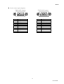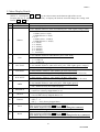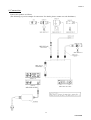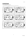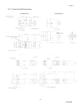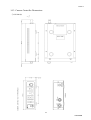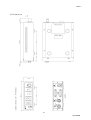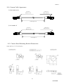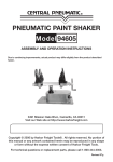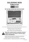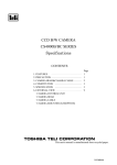
1
VER2.2
CCD COLOR CAMERA
CS9001/CS9001P SERIES
ISTRUCTION MANUAL
For customer Use:
Enter below the Serial No. which is located on the rear panel of the camera control unit.
Retain this information for future reference,
Model name.
Serial No.
This Instruction Manual is printed on recycled paper.
D4122436B
VER2.2
CONTENTS
Page
Important Safety Precautions
1
1. Introduction
8
2. Features
8
3. Components
9
3.1. CS9001 Series
9
3.2. CS9001P Series
10
3.3. Option
11
4. Names and Description of the Camera Controller
12
5. Menu Display Details
16
6. Connection
17
7. Operation
18
8. Before considering a failure has occurred
18
9. Specification
19
10. Attached Drawings
22
10.1. Typical spectral response
22
10.2. Camera Head Dimensions
23
10.3. Camera Controller Dimensions
25
10.4. Camera Cable Appearance
27
10.5. Camera Head Mounting Bracket Dimensions
27
D4122436B
VER2.2
Important Safety Precautions
The main unit and the user's manual of the product provide information on important
contents that will help prevent injury to those using the product and others, prevent property
damage, and ensure safe use of the product. Please make yourself familiar with this
information before using your CCD camera.
Make sure you understand the meaning of the indications and graphic symbols shown below
before reading this manual. Be sure to observe the precautions indicated.
●Description of indications
Indication
Meaning of indication
DANGER
Incorrect use or disregarding precautions may result in death or serious
injury
WARNING
Incorrect use or disregarding precautions may result in death or serious
injury
CAUTION
Incorrect use or disregarding precautions may result in personal injury
(*1) or damage to property (*2).
*1: Personal injury refers to injuries, burns, or electric shock
repeated hospital isits.
*2: Property damage refers to damage to assets or materials.
that does not require hospitalization or
●Description of graphic symbols
Graphic symbol
Meaning of graphic symbol
Prohibited – actions to be avoided at all times. The prohibited actions are indicated
within or near the graphic symbol with illustrations or text.
Required – actions or that must be taken. The required actions are indicated within
or near a graphic symbol with illustrations or text.
Hazardous. The nature of the hazard is indicated within or near the graphic symbol
with illustrations or text.
Caution. The reason for the precaution indicated within or near the graphic symbol
with illustrations or text.
1
D4122436B
VER2.2
[About Instructions in General]
DANGER
Unplug
If by any chance an unusual odor, overheat or heat is found, turn off the power switch
immediately and unplug the power cord from the power outlet.
If you use it as is, this can cause fire, electric shock or product failure. Contact the sales
distributor for repair.
Any repair by the user is strictly prohibited because it is dangerous..
Unplug
If a failure such as no image appears on the screen, turn off the power switch immediately and
unplug the power cord from the power outlet.
If you use it as is, this can cause fire, electric sock or product failure. Contact the sales
distributor for repair. Any repair by the user is strictly prohibited because it is dangerous.
Unplug
Unplug
Unplug
NEVER
pull apart
If a failure such as no image appears on the screen, turn off the power switch immediately and
unplug the power cord from the power outlet.
If you use it as is, this can cause fire, electric sock or product failure. Contact the
sales distributor for repair. Any repair by the user is strictly prohibited because it is
dangerous.
If by any chance a foreign object gets inside the product, turn off the power switch immediately
and unplug the power cord from the power outlet.
If you use it as is, this can cause fire or electric shock. Contact the sales distributor for
repair.
If by any chance you have dropped the product or the case is damaged, turn off the power
switch immediately and unplug the power cord from the power outlet.
If you use it as is, this can cause fire or electric shock. Contact the sales distributor for
repair.
The user must not disassemble, repair or modify the product.
This can cause a failure of the product, erroneous operation or an accident.
Contact the sales distributor for repair.
2
D4122436B
VER2.2
[About Instructions in General]
DANGER
Avoid
Avoid
The camera cable, video output cable and power cord must not be handled roughly, damaged,
fabricated, bent forcefully, pulled, twisted, bundled, placed under heavy objects or heated.
If damaged, this can cause fire or electric shock. If the camera cable, video output cable or
power cord is damaged, contact the sales distributor for repair.
Do not remove the cover of this product.
This can cause electric shock. For inspection, adjustment or repair inside of the product, contact
the sale distributor
Do not use voltage other than specified voltage (DC12 V).
This can cause fire or electric shock.
Avoid
Do not place the product on an unstable place such as a shaky table or a sloped location.
If the product falls or topples down, this can cause injury.
Avoid
Avoid
Avoid
Do not place a vase, flower pot, cup, toilet articles, vessels containing medicament or water, or
small metal pieces on top of this product.
If any of these spills or gets inside, this can cause fire or electric shock.
Do not insert or drop a foreign object such as a metal piece or highly combustible objects to
inside of the product from a vent hole or other of this product.
This causes a failure of the product or erroneous operation and can result in an accident.
To repair the product, contact the sales distributor.
3
D4122436B
VER2.2
[About Instructions in General]
CAUTION
Unplug
When you clean the product or not using the product for a long time, unplug the power cord
from the power outlet for reason of safety.
This can cause fire or electric shock.
To connect between the devices, make sure the power switch is turned off.
This can cause electric shock.
Avoid
To unplug the power cord from the power outlet, do not pull the cord.
The cord may be damaged and this can cause fire or electric shock.
Avoid
Do not unplug the power cord with wet hand.
This can cause electric shock.
Avoid
Avoid
Avoid
Do not block the vent hole of the product by putting a blanket over or placing another device
close to the product.
The temperature inside the product rises and this can cause fire.
Do not place this product, camera cable, video output cable or power cord close to a heating
device.
The sheath of the switch, cable or cord melts and this can cause fire or electric shock.
To clean this product, do not use benzine, alcohol, thinner and so on.
This can cause painting or markings to peel off or degenerate.
Avoid
To insert or extract a connector, make sure the power of the camera controller is turned
off beforehand. This can cause a failure of the product or electric shock.
Caution
4
D4122436B
VER2.2
[About Instructions in General]
CAUTION
Caution
Caution
If this product is to be used in an electric or magnetic field, beat noise (stripes generated
vertically, horizontally and sideways) may occur in video output.
In this case, take necessary action to dispose of the source of electromagnetic waves so
that the product will not be affected by electromagnetic waves.
Even when using this product repeatedly, observe the operating environmental condition
(temperature and humidity). The temperature inside the product rises and this can cause fire.
Do not install this product in a location where vibration is strong. This can cause a failure of the
product.
Caution
Caution
Do not apply strong shock to this product. This can cause a failure or damage to the product.
In addition, if the product is used under environment where strong shock is applied to its
connector, the connector can be damaged.
Do not short the signal output. This can cause a failure of the product.
Caution
Regardless of the operating condition of this product, do not direct the CCD camera to
ward the sun. This can cause a failure of the product.
Caution
Caution
Caution
Required
Even when this product is not used, place lens or lens cap so that dust does not collect and no
scratches occur on the surface of the CCD camera. If stain occurs on the glass surface, wipe it
off with a cotton swab or something.
If solvent is required, do not use organic solvent other than ethyl alcohol.
To prevent condensation, take necessary measures such as to cool when heated or warm when
chilled before going in or out of the room with extreme temperatures.
To install lens on the camera head, make sure the lens is not slanted before installing it on the
camera head.
In addition, use the one with no scratches or dust on the mounting threads. The camera
may get stuck and not be removed.
To dispose of this product, follow the regulations of your state or the ordinance stipulated by
local government.
To prevent environmental contamination, excise the appropriate discriminative disposal method.
5
D4122436B
VER2.2
This equipment has been tested and found to comply with the limits for a class A digital
device, pursuant to Part 15 of the FCC Rules.
These limits are designed to provide reasonable protection against harmful interference when
the equipment is operated in a commercial environment.
This equipment generates, uses, and can radiate radio frequency energy and, if not installed
and used in accordance with the instruction manual, may cause harmful interference to radio
communication.
Operation of this equipment in a residential area is likely to cause harmful interference in
which case the user will be require to correct the interference at his own expense.
RESTRICTION FOR USE
1. In case malfunction of this equipment (e.g. video output cut-off) can be expected to lead to significant
accident, avoid using this equipment for such system build-in use.
2.Avoid irregular signal interface.
Do not attempt irregular signal interface other than specified. Under signal interface other than
recommended/specified in this instruction manual, the device might fail to exert the maximum
performance. In much worse case, if you continue to use your device under incorrect signal interface,
part(s) of inner circuits might burn down.
DISCLAIMER (LIMITED WARRANTY)
We disclaim any responsibility and shall be held harmless for damages or losses incurred by user(s) in
either of the following cases.
1. In case damages or losses are caused by fire, earthquake, or other acts of Gods, the act by third party,
misuse by the user deliberately or erroneously, use under extreme operating conditions.
2. In case any indirect, additional, consequential damages (loss of expected interest, suspension of business
activities) are incurred as results of malfunction or non-function of this device, we shall be exempted from
assuming responsibility for such damages.
3. In case damages or losses are caused by incorrect use which is not in line with the instructions given in
this instruction manual.
4.In case damages or losses are caused by malfunction resulting from bad connection with other equipment.
5.In case damages or losses are caused by repair or modification done by the user.
6
D4122436B
VER2.2
OTHER INSTRUCTIONS
Do NOT use power other than specified
Be sure to use DC12V power supply. The camera is designed to work only under the specified voltage. Do
NOT attempt to drive the camera with the power other than DC12V. Operating the camera under power
other than DC12V invites a fire or a electric shock hazard.
Avoid intensive light
Do NOT expose the camera’s image-pickup-plane to sunlight or other intense light directly. If the part of
CCD is exposed to spot-intensive light, you might get a picture problem like blooming and/or smear. You
might observe vertical stripes on your monitor if your camera is exposed to sunlight (or any other intensive
light), however, this is not a malfunction. Redirect your CH (camera-head) to different directions in such
case.
Use under right operation condition
This equipment is designed and guaranteed to work under the temperature range of 0 to 40 degrees C and 10
through 90% humidity range. Avoid using the equipment beyond that limits.
Handle with care
Take care not to drop the equipment, nor give strong impact, as this may cause breakdown.
Do NOT tamper with switches
Read this operation guide thoroughly before you touch switches and adjusters on the rear panel. Do NEVER
attempt to disassemble the camera and/or tamper with any inner switches, potentiometers, etc.
Avoid liquid
Avoid placing the camera where it is likely to be splashed with water or any other fluids. Operating the
camera with its inner parts/circuits in an wet condition might cause a damage or an electric shock accident.
About camera cable
The connector of the camera cable is in “screw-coupling” lock structure. Improper cramping might cause
image noise. Be sure to give it a good cramping to avoid noise.
Camera cable connection/disconnection
Before connecting/disconnecting connectors, make sure to turn camera power OFF. Otherwise, your camera
might break down.
Avoid placing near TV/radio
This camera might cause an interference (e.g. noise) if used around radio / TV set. In such a case, change the
location of your camera (or radio / TV).
Abnormal operation
In the event that any abnormal condition is observed, turn the power switch OFF immediately. Do NOT try
to continue to use the camera. To do so reckless of visible signs of malfunction invites a fire, an electric
shock hazard, or any other serious damage to the camera. In such case, contact us or our dealer/distributor
7
D4122436B
VER2.2
from which you purchased the camera for repair service.
1. Introduction
The CS9001/CS9001P Series is an NTSC/PAL separation method remote head type color camera and is
adaptable to a variety of camera heads realizing ultra-small size and light weight.
2. Features
(1) DC12 V Drive
Power voltage of this product is DC12 V suitable for assembly within a device. When the product is to
be used under 100 to 240 VAC, it is recommended that you use an optional power adapter.
(2) Camera head (the shape of CCU is common)
Four types of camera heads are provided to correspond to the size of CCD: 1/2, 1/3, 1/4 and 1/6.
For the shape of the head, φ17 cylindrical type and φ29 C-mount type are provided for Type 1/2,
φ12 cylindrical type for Type 1/3, φ12 cylindrical type (camera cable directly connected) for Type
1/4, and φ7 cylindrical type (camera cable directly connected) for Type 1/6. These combinations of
camera heads can be used for a wide range of applications.
* However, the camera head for Type 1/6 is used only for NTSC only.
(3) External synchronization (CSU9001-01/CSU9001P-01 only)
Using an external synchronization signal as input, the synchronization method is automatically
changed to remote mode.
When VBS,SYNC,HD/VD signal is used as the external synchronization signal, the horizontal and the
vertical phases will be synchronized.
(4) ALC (automatic light control)
Optimum image against extensive light intensity variation can be obtained with microcomputer-based
control combining the high speed electronic shutter (ELC) with max speed of 100 hundred thousandth
of a second and the automatic gain control (AGC). This is suitable for microscope applications with no
lens aperture control or applications where brightness changes extensively.
(5) Auto white balance
Burdensome white balance adjustment is not required by means of auto follow-up full automatic
control that maintains appropriate white balance by detecting the color temperature variation of the
subject at all times.
In addition, the set function to memorize and maintain the balanced white condition as well as the
manual control of white balance can be made, which is convenient to obtain images under illumination
with fixed color temperature used for image processing etc.
(6) S terminal output
Y/C separation signal output (S terminal) is provided as well as VBS output.
By connecting the signal to an imaging device equipped with S terminal color monitor, clear images
with less cross color can be obtained.
8
D4122436B
VER2.2
(7) RGB output (CSU9001-01/CSU9001P-01 only)
RSB output useful for image processing is provided.
(8) Various camera cables
Camera cables for φ17, φ12 cylindrical type (for Type 1/3) and C-mount type camera head include
optional 3 m and 5 m length cables and they are available for each type.
In addition, camera cables for φ12 cylindrical type (for Type 1/4) and φ7 cylindrical type camera
head are 3 m and 5 m length directly connected cables.
Furthermore, these can be combined with an extension camera cable of 7m.
3. Components
3.1. CS9001 Series (NTSC)
(1) Camera head , Camera cable
A combination of camera heads and camera cables are shown in the following table. Please specify
the desired combination to our sales distributor when ordering.
Camera head
Individual
product name
CCD Size
Dimensions
Lens mount
Accessories
CSH9201
Type 1/2
φ17 mm
M15.5 P0.5
(Male thread)
None
CSH9221
Type 1/2
φ29 mm
C-mount
Lens Screw
CSH9301
Type 1/3
φ12 mm
M10.5 P0.5
(Male thread)
None
CSH9401-03
CSH9401-05
Type 1/4
φ12 mm
M10.5 P0.5
(Male thread)
None
CSH9501-03
CSH9501-05
Type 1/6
φ7 mm
M6.3 P0.5
(Female thread)
None
Camera cable
The following camera cable (option) can be
connected.
- 3 m: CPRC4000B-03
- 5 m: CPRC4000B-05
- Extension 7 m: CPRC4000B-07J
3m and 5m cables are connected directly from
the camera head.
- 3 m : 03 (the last 2 digits of product name)
- 5 m : 05 (the last 2 digits of product name)
In addition, the cable can be extended with the
cable below (option).
- Extension 7 m: CPC4000B-07J
(2) Camera controller
Camera controller
Individual
product name
Dimensions
CSU9001
Synchronous method
Video output
Consumption
current
Internal synchronization
VBS OUT × 1
Y/C OUT × 1
550 mA
Internal synchronization
/External synchronization
VBS OUT × 1
Y/C OUT × 1
RGB OUT × 1
680 mA
120(W) × 41(H) × 156(D) mm
CSU9001-01
Accessories
Instruction
Manual
9
D4122436B
VER2.2
3.2. CS9001P Series (PAL)
(1) Camera head , Camera cable
A combination of camera heads and camera cables are shown in the following table. Please specify
the desired combination to our sales distributor when ordering.
Camera head
Individual
product name
CCD Size
Dimensions
Lens mount
Accessories
CSH9201P
Type 1/2
φ17 mm
M15.5 P0.5
(Male thread)
None
CSH9221P
Type 1/2
φ29 mm
C-mount
Lens Screw
CSH9301P
Type 1/3
φ12 mm
M10.5 P0.5
(Male thread)
None
CSH9401P-03
CSH9401P-05
Type 1/4
φ12 mm
M10.5 P0.5
(Male thread)
None
Camera cable
The following camera cable (option) can be
connected.
- 3 m: CPRC4000B-03
- 5 m: CPRC4000B-05
- Extension 7 m: CPRC4000B-07J
3m and 5m cables are connected directly from
the camera head.
- 3 m : 03 (the last 2 digits of product name)
- 5 m : 05 (the last 2 digits of product name)
In addition, the cable can be extended with the
cable below (option).
- Extension 7 m: CPC4000B-07J
(2) Camera controller
Camera controller
Individual
product name
Dimensions
CSU9001P
Synchronous method
Video output
Consumption
current
Internal synchronization
VBS OUT × 1
Y/C OUT × 1
550 mA
Internal synchronization
/External synchronization
VBS OUT × 1
Y/C OUT × 1
RGB OUT × 1
680 mA
120(W) × 41(H) × 156(D) mm
CSU9001P-01
Accessories
Instruction
Manual
10
D4122436B
VER2.2
3.3. Option
The following products are provided as option. (For details, contact our sales distributor.)
(1) Camera cable
: CPRC4000B-03 (3m)
: CPRC4000B-05 (5m)
(2) Extension camera cable
: CPC4000B-07J (7m)
(3) AC adapter
: CA300
(4) AC cord
: APC1025-01P[for AC100V](2.5m)
(5) RGB output cable (for CSU9001-01/CSU9001P-01)
(6) Lens
(7) Camera head fixture
(8) C-mount adapter (for φ17 mm, φ12 mm)
CAUTION: About option parts and EMC performance
EMC performance of this product is guaranteed only when this product is combined with the option
parts shown above. EMC performance when this product is combined with parts other than the ones
specified by Teli shall not be guaranteed.
CAUTION: Combination of camera heads and controllers
Make sure to use the CSH9001(P) Series (camera head) combined with the CSU9001(P) or
CSU9001(P)-01 (camera controller).
Do not combine the Teli’s conventional CS9000(P) Series with them.
This can cause a failure of the product.
CSH9201(P)
CSH9221(P)
CSH9301(P)
CSH9201(P)
CSH9221(P)
CSH9301(P)
CSU9000(P)
CSU9000B(P)
CSU9001(P)
CSU9001(P)-01
CSH9200(P)
CSH9220(P)
CSH9300(P)
CSH9400(P)
CSU9001(P)
CSU9001(P)-01
CAUTION: About the camera head CSH9401(P)-03/05
The camera head CSH9401(P)-03/05 is structured with its cable connected directly.
Disassembly of the connector part is strictly prohibited.
NEVER pull apart
11
D4122436B
VER2.2
4. Names and Description of the Camera Controller
(1) Front panel
⑥
⑤
④
③
②
①
Camera controller CSU9001(P)/CSU9001 (P)-01 Rear panel
① Power switch
② SELECT
(1) △
key
(2)
key
▽
③ DATA
(1)
+
(2)
-
key
key
: Turns on or off the power to the camera.
: Pressing the key once shows menu at the bottom right of the screen
and pressing the key more than once changes the menu.
: Pressing the key once shows menu at the bottom right of the screen
and pressing the key more than once changes the menu.
: Changes the setting value of the displayed menu.
: Changes the setting value of the displayed menu.
④ ALC
ALC is the function to adjust the shutter speed and gain (video gain) automatically so that
proper images in accordance with the brightness of the subject can be obtained. Use the ALC
key on the front panel of the camera controller to set.
(1) ALC LED
: Changes as follows with the set ALC mode
lights (orange) ⇒ lights (green) ⇒ unlit
(2) ALC key
: Used to change the ALC mode.
Shutter
Speed
ALC
MODE
LED
ALC
Lights
(green)
AUTO
AUTO
AGC
Lights
(orange)
MANU
AUTO
MANU
Unlit
MANU
MANU
Gain
Description
Automatically adjusts the shutter speed and gain
(video gain) to obtain proper video level in accordance
with the brightness of the subject. In this mode, the
detection area can be set on the menu screen.
Automatically adjusts only the gain (video gain) to
obtain proper images in accordance with the brightness
of the subject.
However, the shutter speed becomes fixed. Adjust the
speed on the menu screen to obtain proper video level.
The shutter speed and gain become fixed. Adjust them
on the menu screen while checking images on a video
monitor etc.
12
D4122436B
VER2.2
⑤ W. BAL
(1) W. BAL LED
(2) W. BAL key
: Changes as follows in accordance with the set white balance mode
lights (green) ⇒ lights (orange) ⇒ unlit
: Used to change the white balance mode.
This camera has the following modes to adjust white balance. Set the mode in accordance
with the subject.
WHITE
BALANCE
MODE
LED
AUTO
Lights
(green)
SET
Lights
(orange)
MANU
Unlit
⑥ Camera connector
Description
At all times, adjusts white balance automatically. This is effective
for the subject that changes its color temperature over time.
However, since the color detection is made by means of
integration, if illumination condition is bad (light intensity is too
much or too little, or the color temperature shows extreme values),
this mode may not work correctly.
If the mode is changed from AUTO mode to this mode, the white
balance condition at that time will be retained and memorized.
After adjusting the white balance in the AUTO mode, change the
mode to this mode.
Even if power is turned on or off, white balance does not change.
Using a white subject to obtain images, adjust proper value on the
menu screen while checking images on a video monitor or a vector
scope.
This is effective to obtain images of the subject that does not
change its color temperature over time.
: Used to connect an optional camera cable.
13
D4122436B
VER2.2
(2) Rear panel
③
②
①
⑧
⑤
⑦
⑥
Camera controller CSU9001 (P) Rear panel
③
④
②
①
Camera controller CSU9001 (P)-01 Rear panel
① VIDEO
② S-VIDEO
③ DC12V IN
Mating plug
④ RGB OUT
⑤ EXT. SYNC
: The output connector of the composite vide signal to connect to a monitor etc.
: Y/C output connector to connect to a monitor etc.
: The connector to supply power to the controller.
: EIAJ RC-5320A Voltage category 4
: RGB/SYNC output connector and used to connect to a monitor etc.
: The input connector for an external synchronization signal.
If the synchronization signal comes in, the system will be automatically
controlled by the external synchronization signal.
⑥ H PHASE
: Used to adjust the horizontal connection phase when external synchronization
is used.(Input signal : HD/VD only)
⑦ EXT. IN
: Used to set in accordance with the input signal when external
synchronization is used.
Input signal
Switch〝EXT. IN〟 setting
HD
HD/VD
SYNC
VBS or SYNC
⑧ SYNC
: Changes G output SYNC attachment.
G output SYNC attachment
Switch〝SYNC〟 setting
OFF
None
ON
Provided
14
D4122436B
VER2.2
● D-sub connector pin assignment
④RGB OUT (female)
6
1
No.
1
2
3
4
5
6
7
8
9
7
2
8
3
⑤EXT. SYNC (male)
9
9
4
5
5
Signal name
SYNC GND
R GND
R OUT
G OUT
B OUT
N.C.
SYNC OUT
G GND
B GND
No.
1
2
3
4
5
6
7
8
9
8
4
7
3
6
2
1
Signal name
HD IN
VD IN
VBS IN/SYNC IN
N.C.
N.C.
GND
GND
GND
GND
15
D4122436B
VER2.2
5. Menu Display Details
SELECT Pressing the △ / ▽ key once shows menu at the bottom right of the screen.
Pressing the key as many times as necessary to display the desired item and change the setting with
DATA + / − key.
No.
1
Display item
DISP Clear
2
Shutter
3
Gain
4
ALC Level
5
W.B. RED
6
W.B. BULE
7
AREA
8
ENHANCE
9
SETUP
10
Gamma
11
Save
12
Reset
Details
Clears the displayed item.
Sets the shutter speed.
* ALC MODE: Effective when AGC/MANU[ALC LED: lights (orange), unlit]
0 = OFF
CS9001 Series: 1/60(S)
CS9001P Series: 1/50(S)
1 = F. L
CS9001 Series : 1/100(S)
CS9001P Series: 1/120(S)
2 = 1/250(S)
3 = 1/500(S)
4 = 1/1000(S)
5 = 1/2000(S)
6 = 1/4000(S)
7 = 1/10000(S)
Sets the gain of video signals.
* ALC MODE: Effective when MANU [ALC LED: unlit]
0 = 0 dB (×1)
1 = +6 dB (×2)
2 = +12 dB (×4)
Sets the ALC video signal level.
* ALC MODE: Effective when ALC/AGC [ALC LED: lights (green, orange)]
0 (dark) to 3 (factory shipped data) to 12 (bright)
Sets the white balance RED.
* White balance: Effective when MANU [W. BAL LED: unlit]
+32(R direction) to 0 (center: factory shipped data) to -32 (CY direction)
Sets the white balance BULE.
* White balance: Effective when MANU [W.BAL LED: unlit]
+50 (B direction) to 0 (center: factory shipped data) to -50 (YL direction)
Sets the ALC detection area.
* ALC MODE: Effective when ALC [ALC LED: lights (green)]
OFF = Full screen (factory shipped data)
ON = WIND (Fixed) (No window display)
Sets the contour compensation level (H and V shared).
0 (OFF) to 3 (factory shipped data) to 15
Sets the setup (pedestal) value.
0 to 8 (5 IRE: factory shipped data) to 15
Sets the gamma value.
OFF:γ = 1
ON :γ = 0.45 (factory shipped data)
Saves NO. 2 to No. 9 setting data to memory (USER AREA).
This is executed with DATA + key or - key.
CAUTION: If power is turned off without executing this command,
the changed data becomes invalid.
Read out the factory set data to memory (USER AREA).
This is executed with DATA + key or - key.
CAUTION: If power is turned off without executing DATA Save command,
the factory set data will not be saved to memory (USER AREA).
16
D4122436B
VER2.2
6. Connection
Connect this product as follows:
(The following is just an example of connection. For details, please contact our sale distributor.)
17
D4122436B
VER2.2
7. Operation
(1) See Section 6, “Connection” above to connect necessary devices correctly.
(2) Turn on the power to the connected devices.
(3) Turn on the power to this camera.
(4) If any image appears on the video monitor, adjust the lens aperture control to obtain proper
brightness.
(5) While watching the image on the video monitor, adjust the lens focus to obtain the sharpest image.
(6) White balance adjustment
Adjust the white balance referring to ⑤W. BAL in Section 4, “Names and Description of Camera
Controller.”
(7) Mode setting
Operate necessary items referring to ④ ALC in Section 4, “Names and Description of Camera
Controller.” and Section 5, “Menu Display Details.”
8. Before considering a failure has occurred
Check the following items again before sending it for repair.
Symptom
Checking items
- Is power supplied correctly?
Power does not
- Are camera head and camera cable connected correctly to the camera controller?
turn on.
(If not connected correctly, power to the camera does not turn on.)
- Is power supplied correctly?
Correct
image - Is lens aperture adjusted correctly?
- Are cables connected correctly?
does not appear.
- Are shutter speed and gain set correctly?
- Is white balance adjusted correctly?
Color does not
- Isn’t illumination too dark?
appear correctly.
- Is the monitor adjusted correctly?
- Isn’t the connector of the camera cable loosened?
Noise appears
- Isn’t there something that generates strong magnetic fields nearby?
18
D4122436B
VER2.2
9. Specification
* For items with no indication of head type name, the specification is the camera head CSH9221 or
CSH9221P combined with a camera cable of 3 m.
No.
Model
1
TV system
2
Image sensor
CS9001 Series
NTSC
CS9001P Series
PAL
①CSH9201(P)
Type 1/2 Interline CCD
②CSH9221(P)
Type 1/2 Interline CCD
③CSH9301(P)
Type 1/3 Interline CCD
④CSH9401(P)-**
Type 1/4 Interline CCD
⑤CSH9501-**
Type 1/6 Interline CCD
Scanning area
①CSH9201(P)
6.45mm(H)×4.84mm(V)
6.47mm(H)×4.83mm(V)
②CSH9221(P)
6.45mm(H)×4.84mm(V)
6.47mm(H)×4.83mm(V)
③CSH9301(P)
4.88mm(H)×3.66mm(V)
4.89mm(H)×3.63mm(V)
④CSH9401(P)-**
3.65mm(H)×2.74mm(V)
3.65mm(H)×2.71mm(V)
⑤CSH9501-**
2.46mm(H)×1.84mm(V)
Pixel size
①CSH9201(P)
8.40μm(H)×9.80μm(V)
8.60μm(H)×8.30μm(V)
②CSH9221(P)
8.40μm(H)×9.80μm(V)
8.60μm(H)×8.30μm(V)
③CSH9301(P)
6.35μm(H)×7.40μm(V)
6.50μm(H)×6.25μm(V)
④CSH9401(P)-**
4.75μm(H)×5.55μm(V)
4.85μm(H)×4.65μm(V)
⑤CSH9501-**
3.20μm(H)×3.73μm(V)
Total pixels
811(H)×508(V)
795(H)×596(V)
Active pixels
768(H)×494(V)
752(H)×582(V)
Color filter
Corrective mosaic filter (Ye, Cy, Mg, G)
CCD integration
Field integration (Field-electrical-charge-storage)
3
Scanning lines
525 lines
4
Scanning system
2:1 interlace
5
Scanning frequency
6
7
Horizontal frequency
15.734kHz
15.625kHz
Vertical frequency
59.94Hz
50Hz
Sync system
①CSU9001(P)
Internal
②CSU9001(P)-01
Internal/External
External sync input
HD
VD
SYNC
VBS
8
625 lines
Aspect ratio
automatic switch-over
※Only CSU9001-01 and CSU9001P-01
4±2V(p-p)/High Negative polarity
15.734kHz±50ppm
4±2V(p-p)/High Negative polarity
59.94Hz±50ppm
2±1 V(p-p)/75Ω Negative polarity
fH =15.734kHz±50ppm
fV =59.94Hz±50ppm
1 V(p-p)/75Ω Negative polarity
fH =15.734kHz±50ppm
fV =59.94Hz±50ppm
4±2V(p-p)/High Negative polarity
15.625kHz±30ppm
4±2V(p-p)/High Negative polarity
50Hz±30ppm
2±1 V(p-p)/75Ω Negative polarity
fH =15.625kHz±30ppm
fV =50Hz±30ppm
1 V(p-p)/75Ω Negative polarity
fH =15.625kHz±30ppm
fV =50Hz±30ppm
4:3
19
D4122436B
VER2.2
No.
9
Model
Video output
1.0 V(p-p)/75Ω Positive polarity
VS
C
RGB
VS
Y
1.0 V(p-p)/75Ω Positive polarity
0.286V(p-p)/75Ω
SYNC
TTL level
11
Sensitivity
F8, 3000K
※Only CSU9001-01 and CSU9001P-01
①CSH9201(P)
700 lx
②CSH9221(P)
700 lx
③CSH9301(P)
950 lx
④CSH9401(P)-**
2000 lx
⑤CSH9501-**
3000 lx
3 lx
②CSH9221(P)
3 lx
③CSH9301(P)
5 lx
④CSH9401(P)-**
8 lx
⑤CSH9501-**
S/N
14
Resolution
Negative polarity
F1.4, 3000K,AGC ON, Output level: Approx. 50%
①CSH9201(P)
13
0.7V(p-p)/75Ω Positive polarity
0.714V(p-p)/75Ω Positive polarity
External sync output
Minimum subject illumination
0.3V(p-p)/75Ω
1.0 V(p-p)/75Ω Positive polarity (Only G signal)
10
12
CS9001P Series
※Only for CSU 9001-01 and CSU9001P-01, a RGB output is.
VBS
Y/C
CS9001 Series
12 lx
46dB(p-p)/rms
Horizontal resolution
470 TV lines
460 TV lines
Vertical resolution
350 TV lines
420 TV lines
15
Gamma
ON:0.45 / OFF:1
16
White balance
AUTO/SET/MANU (Initial factory setting: MANU)
Corrective range
17
ALC
ALC setting
Selectable (Initial factory setting: ON :0.45)
2500K~6000K((Detection area: Full screen)
ALC/AGC/MANU selectable (Initial factory setting: MANU)
Corrective range: -6dB~+60dB
Detection area: Full screen/Wind (Initial factory setting: Full screen)
AGC setting
Corrective range: -6dB~0dB
Detection area: Full screen
Electronic shutter: 8 step selectable
(1/60,1/100,1/250,1/500,1/1000,1/2000,1/4000,1/10000s)
MANU setting
Electronic shutter: 8 step selectable
(1/50,1/120,1/250,1/500,1/1000,1/2000,1/4000,1/10000s)
Gain: 0dB/+6dB/+12dB selectable (Initial factory setting: 0dB)
Electronic shutter: 8 step selectable
(1/60,1/100,1/250,1/500,1/1000,1/2000,1/4000,1/10000s)
Electronic shutter: 8 step selectable
(1/50,1/120,1/250,1/500,1/1000,1/2000,1/4000,1/10000s)
18
Pedestal
16 step selectable [0~8.5IRE] (Initial factory setting: 8=5IRE)
19
Enhance
16 step selectable (Initial factory setting: 3)
20
Lens mount
①CSH9201(P)
M15.5 P0.5 (Male thread)
②CSH9221(P)
C-mount
③CSH9301(P)
M10.5 P0.5 (Male thread)
④CSH9401(P)-**
M10.5 P0.5 (Male thread)
⑤CSH9501-**
M6.3 P0.5 (Female thread)
20
D4122436B
VER2.2
No.
Model
CS9001P Series
DC12V±10% (Ripple voltage : 50mV(p-p))
21
Power source
22
Power consumption
23
CS9001 Series
(DC12V)
①CSU9001(P)
Approx. 550mA
②CSU9001(P)-01
Approx. 680mA
Ambient condition
Temperature
0℃~40℃
Humidity
10~90%
Atmospheric pressure
500~1060hPa
24
Outside size
25
Weight
(No condensation)
Refer to outside drawing
・Camera head
①CSH9201(P)
Approx. 16g
②CSH9221(P)
Approx. 45g
③CSH9301(P)
Approx. 11g
④CSH9401(P)-**
Approx. 9g (Cable is not included)
⑤CSH9501-**
Approx. 3g (Cable is not included)
・Camera controller
26
①CSU9001(P)
Approx. 600g
②CSU9001(P)-01
Approx. 800g
Application standard
CE
FCC
EMI
EN50081-1/1992
EMS
EN50082-2/1995
FCC Part15 subpart B Class A
21
D4122436B
VER2.2
10. Attached Drawings
10.1. Typical spectral response
The lens characteristics and light source characteristics is not reflected in table.
CSH9201P/CSH9221P
1.00
0.80
0.80
Cy
Ye
G
Mg
0.60
0.40
0.20
Relative Response
Relative Response
CSH9201/CSH9221
1.00
0.00
Cy
Ye
G
Mg
0.60
0.40
0.20
0.00
400
450
500
550
600
Wave Length [nm]
650
700
400
450
700
1.00
0.80
Cy
Ye
G
Mg
0.60
0.40
0.20
Relative Response
Relative Response
650
CSH9401
CSH9301/CSH9301P
1.00
0.00
0.80
Cy
Ye
G
Mg
0.60
0.40
0.20
0.00
400
450
500
550
600
Wave Length [nm]
650
700
400
450
CSH9401P
500
550
600
Wave Length [nm]
650
700
CSH9501/CSH9501P
1.00
1.00
0.80
0.80
Cy
Ye
G
Mg
0.60
0.40
0.20
0.00
Relative Response
Relative Response
500
550
600
Wave Length [nm]
Cy
Ye
G
Mg
0.60
0.40
0.20
0.00
400
450
500
550
600
Wave Length [nm]
650
700
400
450
500
550
600
Wave Length [nm]
650
700
22
D4122436B
VER2.2
10.2. Camera Head Dimensions.
①CSH9201(P)
②CSH9221(P)
CSH9401-03/05
④CSH94CSH9501-03/05
01(P)-03/05
CSH9401P-03/05
③CSH9301(P)
23
D4122436B
VER2.2
⑤CSH9501-03/05
24
D4122436B
VER2.2
10.3. Camera Controller Dimensions
①CSU9001(P)
25
D4122436B
VER2.2
②CSU9001(P)-01
26
D4122436B
VER2.2
10.4. Camera Cable Appearance
①CPRC4000B-03/05
Connector 2
HR25-9TP-16P
Connector 1
HR25-8TP-14S
Cable length 3/5m
②CPC4000B-07J
Connector 2
HR25-9TP-16P
Connector 1
HR25-9TJ-16S
Cable length 7m
10.5. Camera Head Mounting Bracket Dimensions
27
D4122436B
VER2.2
Sales Department Head Office:
7-1, Asahigaoka 4-chome, Hino city, Tokyo 191-0065, Japan.
Phone:042(589)8771
Fax:042(589)8774
Kansai Office:
1-2, Sakaemachi-dori 2-chome, Chuo-ku, Kobe city 650-0023, Japan.
Phone:078(321)3461
Fax:078(321)3463
Fukuoka Office:
7-21, Hirao 3-chome, Chuo-ku, Fukuoka city 810-0014, Japan.
Phone:092(523)3395
Fax:092(523)3397
28
D4122436B