1
Instrumentation and
Engineering
Services, Inc.
Model 10 Recorder
USER MANUAL
Tel:
(850) 244-2128
[email protected]
Fax:
(850) 244-7979
Tel:
1-850-515-1244
e-mail:
[email protected]
Fax: 1-850-515-1244
151
Mary
IES,
Inc. Esther Blvd., Suite 311
Mary
7552Esther,
Navarre Florida
Parkway 32569-1965
Suite 42
Navarre, FL 32566
DISCLAIMER
The material in this manual is for informational purposes only. The contents and the product it
describes are subject to change without notice. Instrumentation and Engineering Services, Inc.
makes no representations or warranties with respect to this manual. In no event shall
Instrumentation and Engineering Services, Inc. be liable for any damages, direct or incidental,
arising out of or related to the use of this manual or the Event Recorder.
Instrumentation and Engineering Services, Inc. does not warrant that the software program
supplied with this recorder will meet the Customer's requirements or that the program will be
uninterrupted or error free or that all program defects will be corrected. The program and its
documentation are provided "AS IS" without warranty as to their performance or fitness for any
particular purpose. The entire risk as to the results and performance of the program is assumed
by you.
IBM is a registered trademark of International Business Machines Corporation.
FX-80, FX-100, and LQ-1500 are registered trademarks of Epson America, Inc.
ii
PREFACE
This report on the Model 10 Event Recorder was prepared by Instrumentation and Engineering
Services, Inc., 151 Mary Esther Blvd.., Suite 311, Mary Esther, Florida, 32569-1965.
The report consists of a User manual for the Model 10 Event Recorder which contains, in
Section 1, an overview of the recorder, its electrical, power, and physical specifications, and the
factory-configured options available. The operational theory of the recorder is covered in
Section 2 in terms of functional blocks, the interface box, and the operation modes. The
recommended procedures for signal interfacing and thus assuring proper functioning of the
recorder and its collection of accurate data are set forth in Section 3. Correct battery selection,
battery encapsulation procedures, sensor and recorder packaging, and the suitability of a test
fixture to contain the recorder and protect it from physical damage are major considerations in
Section 4. Data retrieval from the Recorder in terms of suggested computers and their interface
with the recorder as well as the software program with the capability to extract, examine, and
print the data are discussed in Section 5.
Appendices A through F contain Recorder Configuration Sheet and Pre-Test Work Sheet;
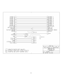
Interface Signal Location and Description; Interface Box Schematic and Computer Readout
Cable; Software Installation; and IES Recorder Data Sheets.
iii
TABLE OF CONTENTS
Section
Title
Page
I
Introduction ........................................................................................................................ 1
Product Overview ......................................................................................................... 1
Specifications................................................................................................................. 1
Electrical.................................................................................................................. 1
Power....................................................................................................................... 2
Physical.................................................................................................................... 2
Options .................................................................................................................... 2
Factory Configuration Options....................................................................................... 2
II
Event Recorder .................................................................................................................... 5
Description .................................................................................................................... 5
Interface Box ................................................................................................................. 5
Arming .......................................................................................................................... 6
Triggering...................................................................................................................... 6
Pre-test Operation .......................................................................................................... 7
Sample Period.......................................................................................................... 7
Current..................................................................................................................... 7
Packaging ...................................................................................................................... 7
Epoxy Encapsulation................................................................................................ 8
Glass Bead Encapsulation ........................................................................................ 8
Paraffin Encapsulation ............................................................................................ 8
III Signal Interface.................................................................................................................... 9
Requirements................................................................................................................. 9
Precautions .................................................................................................................... 9
Interface Examples......................................................................................................... 9
Impact Switch .......................................................................................................... 9
Trigger Signal ........................................................................................................ 10
Explosive Sensing Switch ...................................................................................... 10
Switched Ground ................................................................................................... 11
IV Battery .............................................................................................................................. 13
Requirements............................................................................................................... 13
Voltage .................................................................................................................. 13
Current................................................................................................................... 13
Capacity................................................................................................................. 13
Size........................................................................................................................ 13
Shock Survivability................................................................................................ 13
iv
Encapsulation............................................................................................................... 13
Compound Formulation ......................................................................................... 14
Mold Preparation.................................................................................................... 14
Container Preparation............................................................................................. 14
Compound De-aeration .......................................................................................... 14
Procedure............................................................................................................... 15
Cure ....................................................................................................................... 15
V Data Retrieval ................................................................................................................... 17
Computer Interface ..................................................................................................... 17
Interface Box Connection ..................................................................................... 17
Recorder Connection ............................................................................................. 17
Battery Check ....................................................................................................... 14
Data Extraction Software ............................................................................................. 17
Mouse Techniques ................................................................................................. 17
Software Commands.................................................................................................... 18
Starting IES............................................................................................................ 18
Opening Menu ....................................................................................................... 18
Input Data From Recorder...................................................................................... 18
Read Data From Disk............................................................................................. 21
Display................................................................................................................... 23
All Channels .......................................................................................................... 23
Every Point ............................................................................................................ 24
Min / Max .............................................................................................................. 24
Redraw................................................................................................................... 24
File......................................................................................................................... 24
Copy ...................................................................................................................... 24
Change Dir............................................................................................................. 25
Editor..................................................................................................................... 25
Rename.................................................................................................................. 26
Save ....................................................................................................................... 26
Save As.................................................................................................................. 26
Help ....................................................................................................................... 27
Plot ........................................................................................................................ 27
Quit........................................................................................................................ 28
Utilities .................................................................................................................. 28
Configure............................................................................................................... 28
Data Out ................................................................................................................ 28
Info ........................................................................................................................ 30
Reset Data.............................................................................................................. 31
Select Ch 0............................................................................................................. 31
Zoom ..................................................................................................................... 32
All.......................................................................................................................... 32
Full X..................................................................................................................... 32
Full Y..................................................................................................................... 32
Magnify ................................................................................................................. 33
v
Previous ................................................................................................................. 33
Segment ................................................................................................................. 33
Window ................................................................................................................. 33
X Window ............................................................................................................. 33
List Data ................................................................................................................ 35
Utilities .................................................................................................................. 35
Help ....................................................................................................................... 35
Quit........................................................................................................................ 35
Appendix A, Event Recorder Configuration............................................................................. A1
Appendix B, Interface Signal Location and Description ........................................................... B1
Appendix C, Interface Box Schematic...................................................................................... C1
Appendix D, Software Installation ........................................................................................... D1
Appendix E, Pascal Data Retrieval Software.............................................................................E1
vi
SECTION I
INTRODUCTION
Product Overview
The Model 10 is a compact, high shock, solid-state recorder designed to acquire timing
information during testing in hostile field environments. The epoxy encapsulated unit was
originally designed to evaluate fuze performance during weapon impact and penetration of
concrete targets. In addition to weapon testing, the recorder is suitable for collecting timing
information during automotive crash testing, blast testing, or any type of system development
testing.
To instrument a fuze function without disturbing the fuze environment, the Event
Recorder was designed to fit in the same volume and have approximately the same weight as a
standard 125 gram general purpose bomb fuze booster pellet. The Event Recorder and an
explosive interface, described in this manual, allow fuze function instrumentation without any
prior modification of the fuze.
Low power consumption allows instrumentation build-up weeks before the test and
extends the time for data retrieval after the test. Data retrieval from the recorder is accomplished
using a personal computer. The software provided with the recorder enables storage, display and
printing of the data.
Specifications
Electrical
Number of channels ................................................................................................................... 8
Input Impedance ...................................................................................................... CMOS logic
Input Voltage (logical 0) ..................................................................................0.0 to 1.5 volts DC
Input Voltage (logical 1) ......................................................................................3.5 or 5.0 volts*
DC Storage Capacity......................................................................32,768 data points per channel
Sample Period ............................................................................... 500 nanoseconds to 1 second*
Arm Signal...................................................................................................... 3.5 or 5 volt pulse*
Arm Input Impedance ................................................................................................. 1,000 ohms
Arm Hold Time............................................................................................... > 100 nanoseconds
Trigger Signal .............................................................................................. 3.5 or 5.0 volt pulse*
Trigger Input Impedance................................................................................ 1,000 ohms Trigger
Hold Time....................................................................................................... > 100 nanoseconds
Switched Ground Sink Current .............................................................. 4 milliamps (Maximum)
Switched Ground Source Current ......................................................... 8 milliamps (Maximum)
* Factory selectable
1-1
Power
Voltage (5 volt unit)................................................................................................. 7 to 15 volts
Voltage (3.3 volt unit)........................................................................................... 5.5 to 15 volts
Standby current...................................................................................... 10 microamps (typical)
Operating current ..................................................................................... 10 milliamps (typical)
Data retention current ............................................................................ 10 microamps (typical)
Physical
Shock survivability ......................................................................................... Tested to 100,000g
Temperature range .................................................................................................... 0oC to 75oC
Weight......................................................................................................................... 24 grams
Encapsulation.................................................................................................................... Epoxy
Size and shape .......................................................................................................... See figure 1
Options
•
•
•
Factory selectable single or dual oscillators
Built-in input signal pull-up and pull-down resistors on selected channels
Custom interface design and packaging to user specification
Figure 1-1. Event Recorder Size and Shape
Factory Configuration Options
The standard oscillator mode has a constant sample period for all 32,768 data points. A
dual oscillator mode is available. This feature causes the sample period to change after the first
16,383 data points have been taken.
1-2
Input signal pull-up and pull-down resistors have been included in the Event Recorder
design to facilitate instrumentation build-up. A schematic of all available resistors is included in
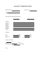
Appendix A. Appendix A contains the configuration of the Event Recorder supplied with this
manual.
Custom interface circuitry design and packaging to user specifications is available.
1-3
SECTION II
EVENT RECORDER
Description
The Event Recorder is capable of simultaneously monitoring and recording the time of
events on eight separate channels. A simplified block diagram of the Event Recorder is shown in
Figure 2-1. The four main functional blocks are the memory, the oscillator, the control logic,
and the power supply. Additionally, interface circuitry is included for eight parallel input
channels and one serial data output. When triggered by an external signal, the Event Recorder
will start sampling the eight input channels and writing data words into memory. Each data
word is eight bits wide and is a binary representation of the eight input channels at that sample
point. The memory is sequentially addressed by the control logic and data words are written into
the memory locations at a frequency (sample frequency) determined by the oscillator frequency.
When data has been written into all of the memory locations, the control logic disables the
oscillator and places the Event Recorder in a low power data retention mode. An external
interface box and a personal computer are used to extract the recorded data. The data retrieval
procedure is described in Section V. Appendix B contains a diagram of the Event Recorder
interface board signal locations and a description of each of these signals.
Figure 2-1. Simplified Block Diagram
Listed below is a description of the interface box, the Event Recorder control signals, the
pretest operations, and the packaging of the recorder.
Interface Box
The interface box has a spring loaded pin array fixture for electrical connection to the
Event Recorder. The interface box also includes a DB-25 computer printer port connector,
banana jacks for recorder input and output signals, and switches to enable arming and triggering
the recorder during bench tests. A schematic of the interface box is shown in Appendix C. The
2-1
recorder is attached to the interface box by inserting the interface box guide pins into the
recorder guide holes. A plate and two wing nuts are used to retain the recorder in the proper
position. The wing nuts should be adjusted so that the spring loaded pins are compressed to
approximately 50% of the pin travel.
Arming
The arm signal provides a method of externally resetting the recorder circuitry and
enabling the trigger input. When the recorder is attached to the interface box, the arm signal can
be generated by depressing the arm switch. The arm signal can also be generated by
momentarily connecting a jumper from the Vdd connection pad to the arm connection pad,
Figure 2-2. Arming is verified by measuring the voltage on the recorder arm indicator
connection pad. An armed indication is a voltage of 3.5 to 5 volts on a 5 volt recorder or 2.5 to
3.3 on a 3.3 volt recorder. Less than 1 volt is an indication that the recorder has been triggered
and has taken data.
Figure 2-2. Signal Locations
Triggering
The trigger signal provides a method of initiating the data collection operation. When the
recorder is attached to the interface box, the trigger signal can be generated by depressing the
trigger switch. The trigger signal can also be generated by momentarily connecting a jumper
from the Vdd connection pad to the trigger input pin, Figure 2-2. The recorder must be in the
2-2
armed condition before it will accept a trigger and it will only accept the first trigger. This feature
prevents multiple trigger signals from causing the recorder to overwrite previously taken data.
Pretest Operation
In the Armed condition, the Event Recorder remains in a low current mode, with the
oscillator off until triggered. When a trigger signal is received by a recorder that is armed, the
oscillator is enabled, data is sequentially written into the 32,768 memory locations, and then the
oscillator is disabled. The period of time that the oscillator functions is determined by the
recorder sample frequency and is usually too short a period for external measurements. Bench
check of the Event Recorder can be made by recording signals from laboratory signal generators,
then reading out the data record to verify the recording operation.
WARNING. All unused channel inputs should be connected to ground or Vdd. If a
channel input is allowed to float, it will record erroneous data and will cause the Event
Recorder current to increase.
Sample Period. The Event Recorder sample period can be measured by recording a
crystal controlled signal, then computing the sample period from the recorded data. To compute
the sample period, display the recorded data and obtain the number of sample points in one
period of the crystal controlled signal. The sample period of the recorder is computed by:
Trec = Tsig / P
where:
Trec = Event Recorder sample period
Tsig = Crystal controlled signal period
P = Number of Event Recorder sample points in Tsig
The recorder sample frequency (oscillator frequency) can be obtained by finding the reciprocal
of the sample period.
Current. Standby current and data retention current are good measures of the Event
Recorder condition. The currents measured when the recorder was constructed are included in
the Event Recorder Configuration Sheet, Appendix A. The recorder current should be measured
before and after each test and compared to the values on the configuration sheet.
Packaging
The Event Recorder has been encapsulated in a shock resistant epoxy resin to enhance the
shock survivability. An additional encapsulation is required to physically locate the recorder
within the test fixture, fill all of the voids, and prevent any motion during hostile environmental
tests. The three methods of encapsulation that have been successfully used are listed below.
2-3
WARNING. It is important to prevent any motion of the recorder while in a hostile
environment. Failure to properly restrain the recorder could result in permanent damage.
Epoxy Encapsulation. This encapsulation provides a rigid method of mounting the
recorder to the test fixture and requires the least amount of space. The recorder must first be
interfaced to all sensors that are to be contained within the encapsulation. Provisions must be
made for the relocation of the input and output signals outside of the encapsulation. The
recorder is positioned and centered within the test fixture. Follow the encapsulating procedure in
Section IV to totally encapsulate the recorder within the test fixture.
Glass Bead Encapsulation. The recorder must first be interfaced to all sensors that are
to be contained within the glass beads. The recorder is positioned and centered within the test
fixture. The test fixture is filled with glass beads (beads with a diameter of less than 0.005" work
well). The test fixture must be constantly vibrated during the filling to insure that all voids are
filled. A compression type of test fixture lid is recommended for this method. After the test the
recorder must be removed from the glass beads to enable the interface box connection.
Paraffin Encapsulation. The recorder must first be interfaced to all sensors that are to
be contained within the paraffin. The recorder is positioned and centered within the test fixture.
Small strips of porous foam function well as centering devices.
The test fixture is filled with paraffin that has been preheated to 75oC (167oF). Fill the test
fixture approximately half full, then slowly agitate the paraffin by moving the test fixture to
insure that all trapped air pockets are allowed to escape. Complete the filling. As the paraffin
cools, shrinking occurs and more paraffin must be added to fill the void.
After the test, the recorder must be removed from the paraffin encapsulation to enable the
interface connection. The procedure is a time consuming process due to the temperature
limitation of the recorder. Position the recorder in an oven and heat to 75oC (167oF) until all the
paraffin has turned to liquid. Care should be exercised in positioning the encapsulated recorder
to insure that the interface board does not make contact with a metal surface as the paraffin
melts.
WARNING. Using heat above 75oC (167oF) exceeds the operating temperature
limits of recorder components and could result in failure of the recorder.
2-4
SECTION III
SIGNAL INTERFACE
Requirements
The Model 10 is an Event Recorder designed to acquire timing information. When
triggered, the Event Recorder will start sampling the eight input channels and write data words
into the memory. Each data word is eight bits and is a binary representation of the eight input
channels at that sample point. The memory is sequentially addressed by the control logic and
data words are written into the memory locations at a frequency (sample frequency) determined
by the oscillator frequency.
The eight input channels have CMOS input impedance and will record a logical high
when the input voltage is between 3.5 and 5.0 volts on a 5 volt recorder or 2.5 to 3.3 on a 3.3 volt
recorder. A logical low is recorded when the input voltage is between 0.0 and 1.5 volts. Any
device or circuit that will produce signals of the correct voltage can be used as an input. The
Event Recorder has a Vdd output that will source 10.0 milliamps of current to power interface
circuitry.
Listed below are interface precautions and several interface examples.
Precautions
To insure proper Event Recorder function, the following precautions should be observed.
1. Do not apply input voltages of greater than Vdd or less than 0 volts. Voltages outside
this range could permanently damage the Event Recorder.
2. All unused channel inputs should be connected to ground or Vdd. If a channel input is
allowed to float, it will record erroneous data and will cause the Event Recorder battery
current to increase.
3. All output signals are from CMOS gates. Standard design precautions for CMOS
should be observed when using any of the output signals. External circuitry that sources
excessive current could permanently damage the Event Recorder.
4. Do not expose the Event Recorder to electrostatic discharges. Due to the CMOS
construction, the recorder can be damaged by accidental over-voltage. Standard CMOS
handling precautions should be observed.
3-1
Interface Examples
Impact Switch. Commercially available impact switches are constructed to function in a
variety of ways and with a wide range of G level thresholds. In weapon impact testing, this type
of switch is very useful both as an Event Recorder trigger switch and as a channel input for
verification that the timing information recorded occurred during a high G environment. Figure
3-1 shows examples of how an impact switch can be interfaced with the Event Recorder. Pull-up
and pull-down resistors, R1 and R2, are built into some Event Recorders. Appendix A contains a
configuration sheet with all optionally available pull-up and pull-down resistors. The
configuration sheet indicates which of the pull-up and pull-down resistors were included in the
Event Recorder delivered with this manual.
Figure 3-1. Impact Switch Use Examples
Trigger Signal. The trigger signal provides a method of initiating the data collection
operation. The Event Recorder must be in the armed condition before a trigger signal can be
accepted (arm indicator must be high). Triggering the Event Recorder is accomplished by
applying Vdd to the trigger input for 100 nanoseconds or longer. The trigger circuitry latches the
input and will only accept the first trigger. Any externally generated signal can be used for
triggering the event recorder. In weapon impact testing, a G switch, positioned to be closed by
the impact shock, is an easy triggering method. The impact switch should be connected between
Vdd and the trigger input. A built-in 1K pull-down resistor simplifies the interface.
Explosive Sensing Switch. The Event Recorder was originally designed to monitor and
record the time of a weapon fuze function in a hostile test environment. The goal was to design
an instrumentation system that would trigger on impact, record a signal to verify that data was
taken during a hostile environment, and record the fuze function delay time after the impact. To
instrument the fuze function without disturbing the fuze environment, the Event Recorder was
designed to fit in the same volume and have approximately the same weight as a standard 125
gram general purpose bomb fuze booster pellet. The explosive sensing switch developed to
monitor the output of the fuze detonator is a simple resistive voltage divider network, Figure 3-2.
Resistor R3 is placed on or sometimes within the recorder (available as an option) and R4 is
mounted directly in line with the output of the explosive device to be monitored. Prior to the
3-2
explosive output, the low impedance of R4 insures that the attached channel records a constant
low. R4 is destroyed by the output of the explosive device and R3 functions as a pull-up resistor,
recording a constant high signal. This method of sensing explosive output provides a clean
indication (transition from low to high) of the function time.
Figure 3-2. Explosive Sensing Switch Example
Warning. Resistor R4 must be securely attached to insure that breakage does not occur
during the hostile environment.
Switched Ground. The switched ground signal is designed to switch to ground when the
Event Recorder is triggered and return to Vdd when the memory is full. This feature is useful in
minimizing the current consumption of circuits such as the one in Figure 3-2 and allows
instrumentation build-up with small batteries in advance of test date. Figure 3-3 is an example of
using the switched ground with the explosive output switch.
Figure 3-3. Switched Ground Example
3-3
SECTION IV
BATTERY
Requirements
Battery selection considerations should include voltage, current drain, required capacity,
size, and shock survivability. A discussion of each of these considerations is listed below.
Voltage. The Event Recorder has been designed to operate from a battery voltage of 7 to
15 volts for 5 volt recorders and 5.5 to 15 volts for 3.3 volt recorders. Insure that the selected
battery is capable of maintaining the minimum voltage for the duration of the test.
Current. The Event Recorder design utilizes CMOS low power circuitry to minimize
current consumption. Maximum current required by the recorder is 10 milliamperes. Insure that
the selected battery can supply the recorder current and any additional current required by the
interface circuitry.
Capacity. The operating current of the Event Recorder, the interface circuitry current,
and the required service life will determine the ampere-hour capacity needed for the battery.
Size. The battery size requirement is driven by the available space in the test fixture.
Shock Survivability. A hostile test environment requires a rugged battery construction.
The recorder memories require constant power to retain the data. Any monetary loss of power
will cause complete loss of data. To insure uninterrupted power in a hostile environment, care
must be taken in selecting and packaging the batteries.
The physical construction of a candidate battery cell should be carefully examined. Cells
that employ contact springs, pressure pads, spring clips or any other device that will allow
motion in a hostile environment should be avoided. Allowing the battery cell components to
move will result in a monetary loss of circuit integrity causing a voltage interruption. Cells
constructed with a gelled mixture and a large conductive surface area are the best candidates.
Batteries constructed of multiple cells should be removed from the outside container to expose
the individual cells. Connections between cells and from the battery pack to the recorder should
be made with spot welded or soldered wire.
WARNING. Use extreme care if battery cells are soldered. Excess heat will cause
some batteries to explode.
Encapsulating
Once the battery type has been selected and the cells have been arranged for the final
battery pack shape, the battery pack is stabilized using an encapsulating compound. A suitable
mold should be constructed to yield the desired final shape. The mold should also include an
4-1
overflow chamber for expansion of the encapsulating compound during the de-aeration process.
The following procedure is an encapsulating example using an epoxy casting resin manufactured
by Emerson and Cuming.
Compound Formulation. The casting compound is formulated from the materials listed
below, taken in the requisite proportions on a weight basis. The tolerance on weights of materials
is + 2 percent. Maximum batch size is 90 grams.
Part A STYCAST 1090SI
Part B CATALYST 24-LV
100 Parts by Weight
23 Parts by Weight
Mold Preparation. The mold or housing should be clean and free of contamination.
When the mold is not an integral part of the component, it should be cleaned and coated with a
suitable mold release agent and allowed to dry.
Container Preparation. All mixing or handling containers should be clean and
moisture-free.
Compound Preparation. For best results during the subsequent de-aeration step, use a
container whose diameter is approximately equal to its height and whose volume is at least four
times the volume of the mixed compound. The requisite amounts of each component should be
combined in accordance with the following procedures:
WARNING. The components of the casting compound may be toxic. Hence, adequate
ventilation should be provided in the handling of the components to prevent exposure to
vapors. Ingestion or skin contact with these materials shall be avoided. If accidental skin
contact should occur, the exposed areas should be washed immediately with soap and
water.
Remove the Stycast 1090SI and Catalyst from the refrigerator and allow them to warm to
room temperature.
Mix the entire contents of the Stycast 1090SI container to a uniform consistency. During
shipment and storage, the low density filler may crust on the top. This is normal and it must be
redispersed by mixing for proper results.
Weigh the desired amount of Stycast 1090SI into a clean container. Castings requiring
more than 75 grams of Stycast should be done in steps to minimize the heat from the exothermic
reaction.
Weigh an amount of Catalyst 24-LV equal to 23 percent of the Stycast 1090SI into another
clean container. Add the Catalyst 24-LV to the Stycast 1090SI and mix thoroughly.
4-2
Compound De-aeration. As soon as the mixing is complete, the mixture should be placed
in a vacuum chamber and evacuated to a pressure of less than 6 inches of Hg absolute (greater than
24 inches of Hg gauge). This reduced pressure should be maintained for at least 5 minutes. The
de-aerated resin mix should be used in the subsequent steps as soon as possible.
Procedure. Introduce the de-aerated casting compound into the mold. The mold should
be filled to the final desired height of the casting. Place the filled mold in a vacuum chamber and
evacuate to a pressure of less than 6 inches of Hg absolute. The reduced pressure should be
maintained for 15 minutes.
Return the mold to atmospheric pressure and remove the mold from vacuum chamber.
Remove the overflow chamber from the mold. Additional casting compound may be
required to fill the mold to the final desired height.
Cure. The filled mold should be cured at room temperature for at least 24 hours.
WARNING. Do not heat the filled mold to accelerate the curing process. Externally
applied heat can aggravate the natural exothermic reaction and permanently damage the
battery.
4-3
SECTION V
DATA RETRIEVAL
COMPUTER INTERFACE
After the Recorder has been triggered and a data record taken, the recorder goes into a
low power standby mode. The recorder remains in the low power standby mode until it is
recovered and the data is extracted. A personal computer and an Interface Box is required for the
data extraction.
Interface Box Connection. The interface box is connected to the computer parallel
printer port with a 25 pin male to male, shielded cable.
WARNING. Use only a shielded cable five foot or less in length. A longer cable may
result in noise and give false data when reading the recorder.
Recorder Connection. The recorder must be attached to the interface box for data
extraction. For recorders with an edge connector, the recorder is attached to the interface box by
plugging the recorder into the edge connector on the box. For recorders with a flat interface
board, the recorder is attached by positioning the interface box guide pins into the recorder guide
pin holes then compressing the recorder onto the spring-loaded interface box pins. Compression
to approximately 50% of the pin travel is adequate for reliable connection. Do not attach the
recorder to the interface box until the computer program IES.EXE has been initiated.
Battery Check. Verify the recorder battery condition prior to retrieving the data. It is
recommended that an external power supply or battery be attached to the interface box
"BATTERY" terminal before reading the recorder to ensure sufficient power. The "BATTERY"
terminal is diode coupled at the recorder battery inputs.
WARNING. Battery current drain increases during data retrieval. Retrieving data
from a recorder with a weak battery could result in loss of data if the recorder is not
attached to an external power source.
DATA EXTRACTION SOFTWARE
The software program "IES" is used to extract, examine, and print the data. The software
installation procedure and the hardware requirements are included in the Software Installation
Appendix of this manual. The software has been written as a menu driven program and the
options can be selected by using a mouse, or in some cases, by pressing the keyboard key of the
first letter of a menu option.
Mouse Techniques. All of the IES data extraction commands (except typing text and
numbers) can be executed using a mouse. You point to an object by moving the pointer until the
tip of the pointer touches the object. Do this by moving the mouse.
5-1
You click by pointing to an object and then pressing and releasing the left mouse button
once. When you click on a button, the selected object either becomes highlighted or a new menu
appears on the screen.
The left mouse button is used to select an option from a menu. After moving the pointer
to the desired option clicking the left mouse button will select this option. In most cases, the
selection can also be made from the keyboard by entering the first letter of the desired option.
The middle mouse button, if present, is used to cancel or abort a command. Clicking the
middle button is the same as pressing the keyboard <Esc> key or selecting the cancel or abort
option from the menu.
The right mouse button is used to accept a configuration menu. After making the desired
changes to a menu, clicking the right mouse button will select it. The <Enter> key on the
keyboard can also be used to accept the selection.
Note. If the mouse has only 2 buttons, the left will be the pick and the right will be the
accept, or return.
SOFTWARE COMMANDS
The commands described below are listed in the order they appear on the menus. Each
menu is listed as it appears on the computer monitor followed by a description of each command
in that menu. This program has been designed in a modular fashion to enable easy additions at a
later date. Some of the options that appear in menus are not currently supported but will be
added. Selection of these options will result in a message informing you that they are not
currently supported.
Starting IES. Insure that you are in the IES directory. Start the IES data extraction
software by entering the command shown below in bold at the system prompt:
C:\IES>IES
OPENING MENU
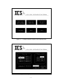
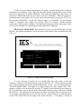
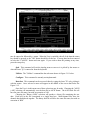
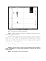
Figure 5-1 shows the opening menu of the program. There are six options which can be
selected from this menu by moving the pointer and clicking on the desired button. These options
can also be selected by typing the first letter of the command. To quit the program at this point
simply click the mouse on "QUIT" or hit the <ESC> key. If a three button mouse is present you
may just click the middle button.
Warning: Do not hook up the interface box to the parallel port until you have entered
the IES program and the main menu (Figure 5-1) can be seen.
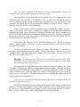
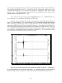
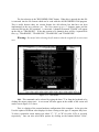
INPUT DATA FROM RECORDER. Figure 5-2 shows the menu when the "INPUT
DATA FROM RECORDER" button is picked.
5-2
Figure 5-1. Computer Monitor Display of the Opening Menu
Figure 5-2. Required Recorder Information
5-3
Note: All of the commands on this menu can also be implemented by selecting the
capitalized letter of the title followed by the specification needed.
This command is used to read data from a recorder, save it in a temporary file called
TEMP.IES, and display the data on the graphics screen. In order to do this properly the user
must first hook up an IES recorder and the correct interface box to the parallel port of the
computer. The button "INPUT DATA FROM RECORDER" can now be picked. Figure 5-2
shows the menu for required recorder information.
A list of valid recorders will now be found in Figure 5-2 under the heading "Recorder".
Access to the buttons can be either by mouse or by keyboard. If using the mouse simply pick
the buttons that match your specifications. If using the keyboard, and a wrong recorder type is
given, the computer will ignore that selection and default to the previous selection. If a recorder
type has been selected from the menu and the recorder being read is actually another selection
from the menu, the results will be erroneous.
To the right of the "Recorder" list is a list labeled "Memory size". This has a variety of
memory options available to the user. To access this list repeat the same process used in
selecting a recorder type.
The next item on the menu is the "Input port" button. This tells the P.C. which port to
use when extracting the data form the recorder. Access to this button is just like access to the
"Recorder" button. The values entered here must be of the decimal form. The value for LPT1 is
888, LPT2 is 632, and LPT3 is 956.
Warning: The three values listed above are the recommended values for LPT1, LPT2,
and LPT3. Using any other values than these may cause the computer to crash, losing
any data that is being read at that time.
The next button that needs to be depressed is either the "turbo oN" button or the "turbo
ofF" button. These buttons can also be depressed by using the keyboard. This turbo function is
used when the cable length or the speed of the P.C. are creating interference of some sort which
leads to erroneous data. When the "turbo ofF" button is selected the retrieval rate of data is
slowed down via the software. This will compensate for the extended cable length or the speed
of the computer, as mentioned above.
Note: Always try extracting the data from the recorder with the turbo mode on first. If
false data is given, turn turbo off.
When all of the options above have been selected, pick the "OK" button or simply hit the
return key. If a three button mouse is being used the right button will also do the same as hitting
the return key. If the program has to be halted for some reason simply pick the "CANCEL"
button, press the <ESC> key, or hit the middle button of a three button mouse.
5-4
If "OK" has been selected, the program will display a prompt asking if the recorder is
connected to the computer. Select "OK" one more time and the recorder will be read, and the
data will be stored in a file named TEMP.IES. If the disk file TEMP.IES already exists, it is
renamed to TEMP.BAK before the new data is stored in TEMP.IES. When the program is
drawing the data on the display, the User may stop the data drawing by pressing the <ESC> key.
If the prompt "WARNING - Invalid EOF Marker Length" or "WARNING - No EOF Marker
Found" is displayed after reading the recorder, check for improper recorder/computer
connections or other possible problems. This indicated the data may not be in the proper order.
If one or more channels are at ground this message might also be displayed.
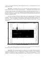
READ DATA FROM DISK. This command is used to read an existing data file from
the disk. The program prompts the User for the name of the data file with a menu that looks like
Figure 5-3.
Figure 5-3. Read Data From Disk Menu
If a new directory is desired, the user should either place the pointer on the title
"Directory" and pick it with the left button or just type the letter "D". The new directory should
now be entered into the space that is provided followed by a return. An error message that says
"INVALID DIRECTORY" will appear if an illegal directory has been entered. Next, "File"
should be clicked on by the mouse or the letter "F" should be type followed by the return key.
The User should now type in the file in the which he/she wishes to retrieve, followed by hitting
the return key. The extension .IES should not be included. If an illegal file has been typed in an
error message will appear that says the file does not exit. Hit the return key or click the mouse
on the "OK" button, followed by typing in the correct file name. If everything is entered in
5-5
correctly the return key should be pressed or the pointer should be clicked on the "OK" button.
The new file will then be retrieved. If no file is desired at this point simply click on the
"CANCEL" button or type "C" to return to the main menu. Pressing the <ESC> key will also
exit this option. When the program is drawing the data on the display, the User may stop the
drawing process by pressing the <ESC> key.
Note: The User may also elect to read a TEMP.IES file if it exists. A TEMP.BAK file can
not be read until it is renamed from TEMP.BAK to TEMP.IES.
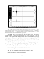
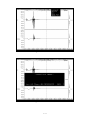
Once the correct directory and file have been selected a screen like the one shown in
Figure 5-4 will be displayed. This screen will have a list of commands along the top horizontal
line of the display, each having its own set of sub-commands. To the immediate right of these
commands will be the file that is being displayed at that time. Along the bottom horizontal is a
line of information describing the point where the red crosshairs is currently located. To the left
is a vertical line of information about the data such as acceleration, voltage, etc., and to the right
is a vertical line of information such as acceleration, declaration, etc. The left and right vertical
axis information can be edited by the user to fit their needs.
Figure 5-4. Data Display
Once the user reaches this screen many options are available to him/her. Commands on
the top horizontal line can be selected in any order. For simplicity sake they will be described
from left to right, and the sub-menu for each command will be described from top to bottom.
5-6
Note: Each command on all of the sub-menus, including the main menu titles, can be
accessed by either clicking the mouse on that command or by typing in the capitalized letter of
the command from the keyboard.
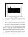
Display. The "Display" command has the sub-menu shown in Figure 5-5 and discussed
below.
Figure 5-5. Display Menu
All Channels. When this is selected all of the channels of that file will be displayed
simultaneously. This command has no effect on single channel recorders.
Individual. When this command is selected a new menu will appear to the left hand
side of the screen. This can be seen in Figure 5-6.
There are three different ways in which the User can select which channels are displayed.
One way is to place the pointer on the desired channel/channels and click once with the mouse
pick button. When all desired channels have been picked, click the mouse on the "OK" button.
Another way is to simply move the pointer on to the actual channels themselves and press the
pick button once. When all desired channels have been selected simply pick the "OK" button. A
third way to implement this command is to type in the number of each channel that is to be
viewed followed by the return key when finished.
5-7
Figure 5-6. Select Channel Menu
Note: When selecting specific channels the User may "undo" a selection by either
clicking the mouse pointer on that particular channel, clicking the mouse pointer on the number
of that particular channel, or by typing that channel in from the keyboard followed by a return.
These selections are setup to operate with the "toggle" effect.
Every Point. This is a way of forcing every data point onto the screen. The User may
select this command by clicking on it with the mouse or by typing the letter "E" in from the
keyboard. After it is selected the command "Redraw" must be picked in order to carry out the
redrawing process. To do this either pick "Redraw" with the mouse or simply type the letter "R"
in from the keyboard. To interrupt the drawing procedure press the <ESC> key. Selecting
"Redraw" will once again regenerate the entire drawing.
Min / Max. This is another drawing feature. Instead of displaying every point on the
screen this command will display only a minimum/maximum representation of the original file.
When the program is in this mode "MIN/MAX DISPLAY" appears at the top of the screen
immediately below the menu bar. This can also be seen in Figure 5-5. This command is selected
in the same manner as "Every Point" was above.
Redraw. Selecting this command will redraw the entire screen.
File. The "File" command has the sub-menu shown in Figure 5-7 above.
Copy. This command is currently not implemented.
5-8
Figure 5-7. File Menu
Change Dir. This command allows the User to change directories without exiting the
main program. To do this use the mouse and pick this command or type the letter "D" in form
the keyboard. Once it has been selected a new menu will appear in the middle of the screen
resembling that of Figure 5-8 below.
To select a new directory click the mouse on the button labeled "Directory", or just type
in the letter "D" from the keyboard. Now enter in the correct drive and path that is desired.
Click on the "OK" button or hit return if everything is OK. If an illegal drive or directory is
entered a warning will appear. When this happens click on the "OK" button or hit the return
key. The program will automatically default back to the original directory and you may proceed
to try again or cancel the command. To cancel pick the "CANCEL" button or type the letter "C"
in from the keyboard.
Editor. The editor is used to store information about the test and data. It consists of 5
pages that can be accessed by using the "NEXT PAGE" and "LAST PAGE" buttons or by using
the <PgUp> or <PgDn> keys. If the "CANCEL" button is pressed, the changes that were made
are ignored. If "OK" is pressed, the information entered is accepted, but not saved to the data
disk file until the "Save" command is used under the "FILE" menu. To select an item to enter
information under, move the mouse arrow inside the desired box, and press the mouse pick
button.
When an edit box is selected, it turns white and an underline cursor appears. When
typing information in the box, the letters are inserted at the cursor position. If the <Insert> key is
5-9
Figure 5-8. Change Director Menu
pressed, "OVERWRITE" will appear on the top of the screen, and characters entered will replace
the characters where the cursor is. The cursor can be moved with the arrow keys. <CONTROL>
arrows move the cursor left or right, one word at a time. <BACKSPACE> and <DEL> keys
delete single characters, and ^T deletes a word. ^Y deletes an entire line. To accept the data,
press <RETURN> or press the right mouse button. To cancel the changes made, press <ESC> or
press the middle mouse button. If editing the "COMMENTS" box, press ^KS or <F10> to save
the changes.
Rename. This command is currently not implemented.
Save. This command will save the data and editor information to a disk file with a .IES
extension. If the file already exists, the User will be asked if they wish to overwrite the current
disk file. They can either overwrite it or cancel the command and leave it as is.
Save As. This can be selected by picking it with the mouse or by typing the letter "A" in
from the keyboard. Once selected a separate menu will appear in the middle of the screen. This
can be seen in Figure 5-9 below.
The User must now choose the correct directory and file name that he/she wishes to save
it as in the same manner as described in the "change Dir" menu. Clicking on the "OK" button
will complete the save or clicking on the "CANCEL" button will ignore the command. The User
will then be returned to the previous screen.
5-10
Figure 5-9. Save As Menu
Note: If the User tries to save a file as the name of a pre-existing file, another menu will
appear in the middle of the screen asking if it should overwrite the old file or not. Click on
either the "OVERWRITE" button or the "EXIT" button. The program will then continue.
Help. This command is currently not implemented.
Plot. When this command is picked a menu will appear in the center of the screen that
looks like Figure 5-10 below.
Note: When the User is in the Plot menu the mouse must be used for all commands
except the button labeled "OK", where the return key can take its place.
In this menu the User selects all available options to fit his/her needs for printing out
data. An "X" in the box next to an option indicates that it is on. A blank box indicates that the
option is off. The "DEVICE", "PORT", and "FORMAT" boxes have the capability of having
only one selection at a time, hence there is no toggle effect when clicking the mouse button twice
on the same option. The "OPTIONS" box has many selections available at one time, so it does
have the toggle effect when the mouse button is pressed more than once on any given choice.
There are three types of printer/plotter selections in the "FORMAT" box. Select the one
that is needed by clicking the mouse pointer on the box next to it.
To set the origins of the paper, rotation of the drawing, and scale of the picture to be
printed, pick the selections in the "POSITION" box. To do this simply move the mouse pointer
to the appropriate box and click on it. The box should change colors. The correct numbers can
5-11
Figure 5-10. Plot Menu
now be entered in followed by a return. When the User is satisfied with all of the data the return
key should be pressed or the "OK" button should be clicked on. If wrong data has been entered
in select the "CANCEL" button and start again. If you wish to abort the printing at any time,
press the escape key.
Quit. This command will exit the Analog menu as soon as it is picked by the mouse or
when the letter "Q" is entered in from the keyboard.
Utilities. The "Utilities" command has the sub-menu shown in Figure 5-11 below.
Configure. This command is currently not implemented.
Data Out. This command can be accessed either by typing the letter "D" or by picking it
with the mouse. Once selected a menu will appear in the middle of the screen that looks like
Figure 5-12.
Once the User is in this menu one of three selections may be made. Choosing the "ASCII
(.AD)" selection will automatically save the data file in ASCII format. The ASCII disk file will
have the same file name, but with an extension of .AD.
Choosing the "Binary (.BIN)" selection will produce a binary file containing the raw
data. Each byte in the file corresponds to a single data byte. Multi-channel files have the
channel data multiplexed together. The binary disk file will have the same file name, but with an
extension of .BIN.
5-12
Figure 5-11. Utilities Menu
Figure 5-12. Data Out Menu
5-13
The last selection is the "RECORDER.COM" button. When this is pressed the data file
is converted into the file format which can be read with the old RECORDER.COM program.
This is useful because there are certain features the old software has that have not been
implemented in the new software yet. The User enters up to a 7 character name and the
converted file has the .IES extension. A converted, 1-channel file named "TRASH" will appear
on the disk as "TRASH0.IES". If the data consists of 4 channels, there will be 4 separate disk
files, e.g. "TRASH0.IES", "TRASH1.IES", "TRASH2.IES", and "TRASH3.IES".
Warning: Be careful when selecting the file name so that the original file is not written
over.
Figure 5-13. Info Menu
Info. This command can be selected by typing the letter "I" in from the keyboard or by
clicking the mouse pointer on it. A new menu will now appear in the middle of the screen and
can be seen in Figure 5-13 above.
This is a display of the current hardware configuration of the computer. It also gives the
User the option of different color displays for best viewing on the type of computer they have.
To select a particular screen setting type either "C", "L", or "R" for color, LCD, or reversed,
respectively. One can also select these options by clicking on the buttons labeled "Color",
5-14
"LCD", or "Reversed" followed by either hitting the return key or clicking the mouse on the
button labeled "OK".
Reset Data. Occasionally, due to noise, the actual data may have been shifted any given
number of bytes when it was being written in memory. Consequently, when the data is read
from the recorder, the output will be shifted on the display screen that same number of bytes, i.e.
the zero bit will be off. To correct this simply pick this command with the mouse or type the
letter "R" in from the keyboard. Figure 5-14 below shows the menu that appears on the screen
when this command is picked.
Now select the button "Zero byte" with the mouse or by typing in the letter "Z" from the
keyboard. Enter in the memory location number where the zero point should be and hit the
return key.
Then, if the number is correct pick the "OK" button or just hit the return key. If
you see that there is a mistake simply pick the "CANCEL" button or type the letter "C" and
begin again.
F
F
Figure 5-14. Reset Data Menu
Note: The location of the new zero point will not be saved to disk until the User
physically picks the save command and elects to save the new data file.
Select Ch 0. This command is used for selecting a new zero channel if the program fails
to correctly identify the correct one. When the new channel is selected all of the remaining
channels are re-numbered, in order, from that point on, i.e. if there are four channels(0,1,2,3) and
channel 2 is selected to be channel 0 then the new order would be (2,3,0,1). However, the
5-15
program will still arrange them on the viewing screen so that the new channel 0 will be first
followed by channels 1, 2, and 3. When this command is selected a menu will appear in the
middle of the screen that looks like Figure 5-15 below.
When this menu is present type in the new 0 channel. If a mistake has been made use the
backspace key to erase the old selection and then enter in the new one. When everything is
correct select the "OK" button with the mouse. If the command is not needed after all simply
pick the "CANCEL" button.
Note: This command is only operational when the file being read is of the multi-channel
type.
Figure 5-15. Select Channel 0 Menu
Zoom. The "Zoom" command has the sub-menu shown in Figure 5-16 below.
All. Displays all channels of data, and the entire data window on the screen.
Full X. This command is for multi-channel use only. It can be selected with the mouse
or by typing the letter "F" in from the keyboard. It displays the entire horizontal data window of
the channel/channels currently displayed.
Note: This command will work with a single channel file, however, the results will
appear the same as if zoom "All" were selected.
5-16
Figure 5-16. Zoom Menu
Full Y. This command is currently not implemented.
Magnify. When this command is selected a menu will appear in the center of the screen
that looks like Figure 5-17 seen below.
This function will magnify or de-magnify the data at the point where the crosshairs are
located. To use it enter a number in the space provided followed by picking the "OK" button
with the mouse. For an example, a value of 10 magnifies the data 10 times about the crosshairs.
A value of .1 de-magnifies the data by 1/10. To center a data point on the screen, place the
crosshair at that point and enter a value of 1. To exit this command without any magnification
just click the mouse on the "CANCEL" button.
Previous. This command returns the display to the previous zoom state. If there is no
previous zoom state it will let you know.
Segment. When the crosshair is placed on a point on the screen and this command is
selected, a data window size of 512 bytes of data is displayed with 256 bytes on either side of the
crosshair position.
Window. This command is currently not implemented.
5-17
Figure 5-17. Magnify Menu
Figure 5-18. X Window Menu
5-18
X Window. This command allows the User to zoom to any size window. When it is
selected a menu will appear on the left side of the screen that looks like Figure 5-18 above.
Two dotted lines will appear and these can be selected by moving the arrow to the line
and pressing the pick button. The line can then be "dragged" with the mouse. To de-select the
line, simply press the pick button again. The other line can be selected, if desired. These dotted
lines indicate where the data will be zoomed to. Actual byte values or times can be selected by
pressing the correct buttons and entering the value from the keyboard. This allows the User to
select a zoom window outside the currently display area.
List Data. This command is currently not implemented.
Utilities. This is the same menu as the "Info" menu mentioned above in the
"UTILITIES" section under the heading "READ DATA FROM DISK". Please refer to Figure 513 and corresponding instructions of that section for more details.
Help. This command is currently not implemented.
Quit. Selecting this command will exit the IES program.
5-19
APPENDIX A
Event Recorder Configuration
A1
Recorder Configuration Sheet
Recorder Model
Recorder S/N
Date
Internal Pull-Up and Pull-Down Resistors:
Pull-Up Resistor
Channel
Channel
Channel
Channel
Channel
Channel
Channel
Channel
Pull-Down Resistor
0
1
2
3
4
5
6
7
Oscillators:
Osc 1
Osc 2
Single Osc
kHz
kHz
kHz
uSec
uSec
uSec
A2
Voltage and Currents:
Vcc
volts
Standby Current
Data Retention Current
Notes:
microamps
microamps
APPENDIX B
Interface Signal Location and Description
B1
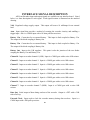
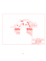
INTERFACE SIGNAL DESCRIPTION
All Event Recorder input and output signals are available on one interface board. Listed
below is a short description of each signal. Each signal location is illustrated on the attached
drawing.
Vdd. Regulated voltage supply output. This output will source 10 milliamps for an external
load.
Arm. Input signal that provides a method of resetting the recorder circuitry and enabling a
trigger input. Arm is a CMOS input with a 1K ohm pull-down resistor.
Battery 1 In. Connection for an external battery. This input is diode coupled to Battery 2 In.
The output of the diode coupling is Battery Out.
Battery 2 In. Connection for an external battery. This input is diode coupled to Battery 1 In.
The output of the diode coupling is Battery Out.
Battery Out. Input to the Vdd regulator. This point is also the junction of the two diodes
coupling the Battery 1 In and Battery 2 In.
Channel 0. Input to recorder channel 0 (LSB). Input is a CMOS gate with a series 10K resistor.
Channel 1. Input to recorder channel 1. Input is a CMOS gate with a series 10K resistor.
Channel 2. Input to recorder channel 2. Input is a CMOS gate with a series 10K resistor.
Channel 3. Input to recorder channel 3. Input is a CMOS gate with a series 10K resistor.
Channel 4. Input to recorder channel 4. Input is a CMOS gate with a series 10K resistor.
Channel 5. Input to recorder channel 5. Input is a CMOS gate with a series 10K resistor.
Channel 6. Input to recorder channel 6. Input is a CMOS gate with a series 10K resistor.
Channel 7. Input to recorder channel 7 (MSB). Input is a CMOS gate with a series 10K
resistor.
Data Out. Serial output of data during read-out of the recorder. Output is a FET with a 5.9K
tied to Pull-up.
External Clock. Input used to clock the recorder memory during data read-out. Input is a
CMOS input with a 10K pull-up resistor.
B2
Guide Hole. Two holes on interface printed circuit board used for alignment when attaching the
Event Recorder to the Interface Box.
Ground. Signal and power return.
Oscillator Out. Output signal of the recorder oscillator. This output is only active while the
recorder is acquiring data. Output is a CMOS gate.
Switched Ground. Interface power reduction signal. Signal is ground only while recorder is
acquiring data.
Trigger. Latched input signal that provides a method of initiating the recorder data collection
operation. CMOS input with a 1K pull-down resistor.
Pull-Up. A 5.9K resistor connected between Data Out and this pad.
B3
B4
APPENDIX C
Interface Box Schematic
C1
C2
APPENDIX D
Software Installation
D1
SOFTWARE INSTALLATION
This appendix covers the essentials of installing the software (IES.EXE) required to
extract, examine, and print data from a recorder.
System Requirements
The suggested computer for retrieving data from the recorder is a standard 386 based
personal computer. The required computer configuration is a 386 computer with a hard disk,
VGA color graphics, a mouse, and a minimum of 2 Meg of EXPANDED memory. It is highly
recommended that the computer also have a math co-processor and a Postscript laser printer for
data printouts.
Installation Procedure
Make a directory named “IES” on your hard drive.
Copy all of the files from the floppy disk supplied with your recorder to the IES directory.
Insure that your computer memory is configured for a minimum of 2048K of EMS expanded
memory and at least 475K of free DOS program memory. If you don’t have enough free DOS
memory, disable some of the drivers in AUTOEXEC.BAT and CONFIG.SYS. Also, run DOS
MEMMAKER or QEMM software to free up more lower DOS memory. If your computer is not
configured for EMS expanded memory, add the line DEVICE=C:\WINDOWS\EMM386.EXE to
your CONFIG.SYS file and reboot your computer. If you are reading a 2 MEG Series 40
recorder, you will need a minimum of 4096K of EMS expanded memory.
NOTE: Do not run this software under Windows.
If you have any questions, please contact:
Instrumentation and Engineering Services, Inc.
151 Mary Esther Blvd. Suite 311
Mary Esther, FL 32569-1965
OFFICE:
FAX:
E-MAIL:
(904) 244-2128
(904) 244-7979
[email protected]
D2
APPENDIX E
Pascal Data Retrieval Software
E1
DATA RETRIEVAL
Although the software program supplied with the recorder is sufficient for most
applications, the User may wish to write their own software. The following Pascal procedure
will read the data stored in the recorder and write it to a disk file. Figure 12 illustrates the printer
port pin assignments. Note: the Analog Read line is not used with digital event recorders.
Parallel (Printer)
25 Pin D-Connector
Port
$378 (Bit 1) -------------------------------> Pin 3 ------->
(Bit ) --------------------------------> Pin 4 ------->
(Bit 3) -------------------------------> Pin 5 ------>
(Bit 4) -------------------------------> Pin 6 ------>
(Bit 5) -------------------------------> Pin 7 ------>
(Bit 7) -------------------------------> Pin 9 ------>
$379 (Bit 3) < ------------------------------ Pin 15 <---- GND
Pins 12,17,19-25
Recorder
Interface
Pull-up Resistor (Pos level)
Reset
(Pos level)
Serial Clock 2
(Pos edge)
Byte Load
(Pos level)
External Clock 1 (Pos edge)
Analog Read
(Pos level)
Serial Data out
GND
procedure READ_DATA_FROM_RECORDER;
var BYTE_COUNT, BINARY_COUNT: integer;
ADD: integer;
DATA, HOLD_DATA, BIT: byte;
DATA_FILE: text;
MAX_BYTES_TO_READ_FROM_RECORDER: integer;
begin
assign (DATA_FILE, 'DATA.IES'); { Open disk file }
rewrite (DATA_FILE);
ADD:= $378; { IBM printer port address }
port [ADD]:= -90; { 10100110 } { Initializes control line, and turns on the
Analog read line. }
delay (500);
{ Delays 500 ms to be sure the A/D is turned on. }
{ Reads the recorder and stores the data on a disk file. }
for BYTE_COUNT:= 0 to MAX_BYTES_TO_READ_FROM_RECORDER do
{ This loop reads the 8-bit words }
begin
{ of serial data.
}
port [ADD]:= -122; {10000110} { Enables memory }
port [ADD]:= -106; {10010110} { Loads data byte into }
port [ADD]:= -122; {10000110} { shift register. }
{ Disables memory - low current mode }
port [ADD]:= -90; {10100110}
DATA:= 0;
for BINARY_COUNT:= 1 to 8 do { Read the 8 bits of data }
{ This loop reads in 8 bits of data }
begin
{ at a time. }
DATA:= DATA shl 1;
{Reads the serial bit from the recorder.}
BIT:= port [ADD+1];
{ NOTE: the serial bit must be read before }
{ the Serial CLOCK 2 line is pulsed.
}
BIT:= (BIT and 8); { Strips off all bits except bit 3 }
if BIT <> 0
then DATA:= DATA + 1;
{ Sends a Serial CLOCK 2 pulse to the }
{ recorder to fetch the next bit of data. }
port [ADD]:= -82; {10101110}
port [ADD]:= -90; {10100110}
end; { for BINARY_COUNT }
DATA:= not DATA;
HOLD_DATA:= DATA;
{ Stores the 8 bits of data in the
disk file DATA_FILE. }
write (DATA_FILE, chr (HOLD_DATA));
end; { for BYTE_COUNT }
port [ADD]:= 38; {00100110}
close (DATA_FILE);
end; { procedure READ_DATA_FROM_RECORDER }
NOTE: LPT1 is generally port $378. If this address does not work, try $278 (LPT2) or
$ 3BC (LPT3)