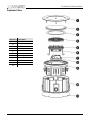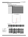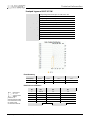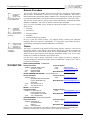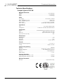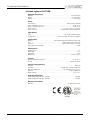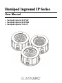
1
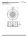
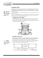
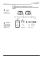
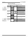
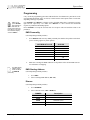
Ilumipod Inground IP Series
User Manual
· Ilumipod Inground 36 IP VW
· Ilumipod Inground 36 IP RGB
· Ilumipod Inground Tri-12 IP
Edition Notes
Edition Notes
The Ilumipod Inground IP Series User Manual Rev. 4 covers the description, safety precautions, installation,
programming, operation, and maintenance of the Ilumipod Inground 36 IP RGB, Ilumipod Inground 36 IP VW,
and Ilumipod Inground Tri-12 IP products. ILUMINARC® released this edition of the Ilumipod Inground IP Series
User Manual Rev. 4 in May 2015.
Trademarks
The ILUMINARC® logo, the ILUMINARC® name, and all other trademarks in this document related to services
or products by ILUMINARC® are trademarks owned or licensed by ILUMINARC®, its affiliates, or subsidiaries.
Any other product names, logos, brands, company names, or trademarks featured or referred to within this
document are the property of their respective trademark holders.
Copyright Notice
The entire content of this document, except where applicable and unless otherwise noted, is solely owned by
ILUMINARC®, a wholly owned trademark of Chauvet & Sons, Inc.
© Copyright 2015 ILUMINARC®
All rights reserved.
Electronically published by ILUMINARC® in the United States of America.
Manual Usage
ILUMINARC® authorizes its customers to download and print this manual for professional information purposes
only. ILUMINARC® expressly prohibits the usage, copy, storage, distribution, modification, or printing of this
manual or its content for any other purpose without its written consent.
Document Printing
For better results, print this document in color, on letter size paper (8.5 x 11 inches), double sided. If using A4
paper (210 x 297 mm), configure your printer to scale the content of this document to A4 paper.
Intended Audience
Any person in charge of installing, operating, and/or maintaining any of these products should read the Guide
that shipped with it and this manual in their entirety before installing, operating, or maintaining the product.
Disclaimer
ILUMINARC® believes that the information contained in this manual is accurate in all respects. However,
ILUMINARC® assumes no responsibility for any error or omissions in this document. ILUMINARC® reserves the
right to revise this document and to make changes from time to time in the content hereof without obligation of
ILUMINARC® to notify any person or company of such revision or changes. This does not constitute in any way
a commitment by ILUMINARC® to make such changes. ILUMINARC® may issue a revision of this manual or a
new edition of it to incorporate such changes.
Document Revision
The Ilumipod Inground IP Series User Manual Rev. 4 supersedes all previous versions of this manual. Please
discard any older versions of this manual you may have, whether in printed or electronic format, and replace
them with this version.
Ilumipod Inground IP Series User Manual
Table of Contents
Table of Contents
1. Introduction ................................................................................................... 1
What is in the Box ........................................................................................................ 1
Unpacking Instructions ................................................................................................. 1
Text Conventions ......................................................................................................... 1
Safety Notes ................................................................................................................. 2
Personal Safety ...................................................................................................................2
Mounting and Installation.....................................................................................................2
Power and Wiring ................................................................................................................2
Operation .............................................................................................................................2
2. Product Description ...................................................................................... 3
Common Features ........................................................................................................ 3
Ilumipod Inground 36 IP VW Features.................................................................................3
Ilumipod Inground 36 IP RGB Features...............................................................................3
Ilumipod Inground Tri-12 IP Features ..................................................................................3
Product Dimensions ..................................................................................................... 4
3. Installation ..................................................................................................... 5
Installation Notes .......................................................................................................... 5
Installation Sleeve Orientation .............................................................................................5
Installation Sleeve Setup .....................................................................................................5
Beam Angle Adjustment ......................................................................................................6
AC Power ..................................................................................................................... 7
Input Voltage and Frequency...............................................................................................7
Power Consumption ............................................................................................................7
Junction Box Wiring...................................................................................................... 7
Power Wiring .......................................................................................................................7
Signal Wiring .......................................................................................................................8
External Wiring ............................................................................................................. 8
Power Distribution ...............................................................................................................8
Signal Distribution................................................................................................................8
Controllers .................................................................................................................... 9
DMX Controller ....................................................................................................................9
ILUMICON ...........................................................................................................................9
Ilumicode ...........................................................................................................................10
4. Operation ..................................................................................................... 11
Ilumicode .................................................................................................................... 11
Ilumicode Panel Description ..............................................................................................11
Menu Map .................................................................................................................. 11
White Functions Menu Map ...............................................................................................11
RGB Functions Menu Map ................................................................................................12
Programming .............................................................................................................. 13
DMX Personality ................................................................................................................13
DMX Starting Address .......................................................................................................13
Dimmer ..............................................................................................................................13
ILUMICON Control ............................................................................................................14
Static Color ........................................................................................................................14
Color Calibration ................................................................................................................14
Color ..................................................................................................................................14
Reset .................................................................................................................................14
DMX Values ............................................................................................................... 15
ARC 1 ................................................................................................................................15
ARC 1 + D .........................................................................................................................15
ARC FULL .........................................................................................................................15
SPECIAL 1 ........................................................................................................................16
Ilumipod Inground IP Series User Manual (Rev. 4)
i
Table of Contents
VW.....................................................................................................................................16
VW + D ..............................................................................................................................16
SOLID ................................................................................................................................16
5. Technical Information ................................................................................. 17
Product Maintenance ................................................................................................. 17
Product Repairs .......................................................................................................... 17
Troubleshooting Guide ............................................................................................... 18
Exploded View ............................................................................................................ 19
Photometrics .............................................................................................................. 20
Ilumipod Inground 36 IP 15º VW .......................................................................................20
Ilumipod Inground 36 IP 30º VW .......................................................................................21
Ilumipod Inground 36 IP 15º RGB .....................................................................................22
Ilumipod Inground 36 IP 30º RGB .....................................................................................23
Ilumipod Inground Tri-12 IP 16º .........................................................................................24
LED Disclaimer........................................................................................................... 25
LED Life .............................................................................................................................25
LED Binning.......................................................................................................................25
Color Rendering Index (CRI) .............................................................................................25
Returns Procedure ..................................................................................................... 26
Claims......................................................................................................................... 26
Technical Specifications ............................................................................................. 27
Ilumipod Inground 36 IP VW ..............................................................................................27
Ilumipod Inground 36 IP RGB ............................................................................................28
Ilumipod Inground Tri-12 IP ...............................................................................................29
ii
Ilumipod Inground IP Series User Manual (Rev. 4)
Introduction
1. Introduction
What is in the Box
This icon
indicates useful,
although noncritical information.
This icon
indicates
important
installation or
configuration information.
Failure to comply with this
information may prevent
the product from
functioning correctly.
This icon
indicates critical
installation,
configuration, or operation
information. Failure to
comply with this
information may render
the product partially or
completely inoperative,
damage third-party
equipment, or cause harm
to the user
· One Ilumipod Inground IP product (36 IP RGB, 36 IP VW, or Tri-12 IP)
· Warranty Card
· Quick Reference Guide
Unpacking Instructions
Immediately upon receiving a product from ILUMINARC®, carefully unpack the carton.
Check the contents of the box to ensure that all parts are present and that they are in good
condition. If any part appears damaged from shipping, or if the carton shows signs of
mishandling, see the Claims section in the Technical Information chapter.
Text Conventions
Convention
1~512
50/60
“ILUMICON UM”
<SET>
SETTINGS
MENU > SETTINGS
1~10
Yes/No
ON
Meaning
A range of values in the text
A set of mutually exclusive values in the text
The name of another publication or manual
A button on the product’s control panel
A product function or a menu option
A sequence of menu options
A range of menu values from which to choose in a menu
A set of two mutually exclusive menu options in a menu
A unique value to enter or select in a menu
The term “DMX”
used throughout
this document
refers to the USITT
DMX512-A transmission
protocol.
Ilumipod Inground IP Series User Manual (Rev. 4)
1
Introduction
There are no
user serviceable
parts inside this
product. Any reference to
servicing it you may find
from now on in this User
Manual will only apply to
properly ILUMINARC®
authorized technicians.
Do not open the housing
or attempt any repairs
unless you are certified to
do so.
Please refer to all
applicable local
codes and
regulations for the proper
installation of this product.
Keep this manual
for future
consultation. If
you sell this product to
another user, make sure
that they also receive this
manual.
In the unlikely
event that your
Ilumipod
Inground IP product may
require service, please
contact ILUMINARC®
Technical Support.
Safety Notes
Please read all the following safety notes carefully because they include important information
on how to install, use, and maintain this product safely.
Personal Safety
· Avoid direct eye exposure to the light source while the product is on.
· Always disconnect the Ilumipod Inground IP product from its power source before
servicing.
· CAUTION: When transferring product from extreme temperature environments, (e.g.
cold truck to warm humid ballroom) condensation may form on the internal electronics
of the product. To avoid causing a failure, allow product to fully acclimate to the
surrounding environment before connecting it to power.
· Always connect the Ilumipod Inground IP product to a grounded circuit to avoid the risk
of electrocution.
Mounting and Installation
· The Ilumipod Inground IP products are for outdoor use and they can work while
submerged in up to 1 m of water (IP67). However, do not submerge it deeper than 1m
for more than (30) thirty minutes.
· Observe the installation instructions regarding drainage to ensure that the water level is
never higher than 1 m for more than (30) thirty minutes to comply with the IP67 rating.
Power and Wiring
· Always make sure that you are connecting this product to the proper voltage, as per the
specifications in this manual or on the product’s sticker.
· Never connect this product to a dimmer pack.
· Make sure that the power cable is not cracked, crimped, or damaged.
· Make sure that the sealed cover is properly adjusted to avoid water entering the unit.
Operation
· The maximum ambient temperature (Ta) is 113 °F (45 °C). Do not operate this product
at a higher temperature.
· In case of a serious operating problem, stop using this product immediately!
2
Ilumipod Inground IP Series User Manual (Rev. 4)
Product Description
2. Product Description
The Ilumipod Inground IP Series encompasses three products, Ilumipod Inground 36 IP RGB,
Ilumipod Inground 36 IP VW, and Ilumipod Inground Tri-12 IP.
Common Features
Other than their
LED configuration
and programming
features, these
three products share the
same dimensions, as well
as the installation, wiring,
and troubleshooting
procedures.
·
·
·
·
·
·
·
·
Remotely addressable DMX-512 LED inground wash light
IP67 ingress protection
IP67 stainless steel gland nuts for cable entry
Adjustable module angle
Cast aluminum and stainless steel housing
Impact resistant tempered glass lens cover (drive-over rated)
Polished stainless steel mounting ring
Ilumicode compatible
Ilumipod Inground 36 IP VW Features
The lenses in
these three
products are nonchangeable.
Therefore, make sure to
use the right product
order code for the desired
lens angle.
· Operating modes:
1-channel:
Dimmer
2-channel:
Warm white, cool white
3-channel:
Warm white, cool white, dimmer
· High power 1 W (750 mA) Warm White and Cool White LEDs
· Installed (non-changeable) optical system:
15° lenses - Product order code: 11036010
30º lenses - Product order code: 11036008
Ilumipod Inground 36 IP RGB Features
· Operating modes:
1-channel:
Dimmer
3-channel:
RGB control
4-channel:
RGB, dimmer
6-channel:
RGB per module
7-channel:
RGB, dimmer, macro, strobe, dimming speed
· High power 1 W (750 mA) Red, Green, and, Blue LEDs
· Blackout/static/dimmer/strobe/pulse
· Installed (non-changeable) optical system:
15° lenses - Product order code: 11036009
30º lenses - Product order code: 11036007
Ilumipod Inground Tri-12 IP Features
· Operating modes:
1-channel:
Dimmer
3-channel:
RGB control
4-channel:
RGB, dimmer
6-channel:
RGB per module
7-channel:
RGB, dimmer, macro, strobe, dimming speed
· High power 3 W (1,050 mA) tri-color LEDs
· Blackout/static/dimmer/strobe/pulse
· Installed (non-changeable) optical system:
16° lenses - Product order code: 11012001
Ilumipod Inground IP Series User Manual (Rev. 4)
3
Product Description
Product Dimensions
(All Ilumipod Inground IP Series models)
4
Ilumipod Inground IP Series User Manual (Rev. 4)
Installation
3. Installation
Installation Notes
Always keep the
power cables
away from the
signal cables by
running them in different
conduits and using
separate distribution
boxes.
The Ilumipod Inground IP products consist of two parts, the product housing and the concrete
installation sleeve. The product housing is IP67 rated, but the installation sleeve is not. Please
pay close attention to the installation instructions for the concrete installation sleeve regarding
leveling and drainage.
You will have to run the AC power and signal cables into the concrete installation sleeve and
the product’s housing.
Do not use the product’s junction box to extend the power or signal cables to other units
because it may compromise the IP rating of the junction box. Instead, use individual cables
from the product to the corresponding distribution boxes.
Installation Sleeve Orientation
Orient the installation sleeve to allow the signal cable to enter the sleeve using one of the four
cable inlets and the power cable to use the opposite inlet, as seen in the figure. This will
reduce the stress to the signal and power cables when setting down the product, while keeping
them separated under the product’s housing.
Installation Sleeve Setup
The Ilumipod
Inground IP
products can
support a distributed load
of up to 3,000 kg (6,614
lbs) when properly
installed.
When setting up the installation sleeve, make sure that any water that may have entered it can
drain out of the sleeve on its own. Locate the installation sleeve above the normal drainage
level so the product is never under more than 1 m of water (IP67) during heavy rain.
In addition, make sure that the installation sleeve and the stainless steel collar are horizontal
and even with the ground surface. This helps to distribute the load uniformly over the
product’s surface and avoids creating dangerous bumps.
Ilumipod Inground IP Series User Manual (Rev. 4)
5
Installation
Beam Angle Adjustment
Make sure to
disconnect the
power to the
product before opening it.
Be careful when
opening and
closing the
product’s housing as it
may compromise the
product’s IP67 rating.
6
The Ilumipod Inground IP products have two LED modules each. You can adjust the angle of
each of these modules to spread or narrow the product’s beam. To do so, follow these steps:
1. Loosen the Allen bolts on the stainless steel collar by turning them CCW, not more
than a turn or two, enough to release the aluminum latch from its “locked”
position.
2. Lift the product from the installation sleeve, making sure not to stretch the power
and signal cables.
3. Loosen four of the six nuts that hold the collar to the housing, leaving untouched
any two adjacent nuts.
4. Wait a few seconds for the seal to expand. This lowers the possibility of damaging
the seal.
5. Complete the removal of the two remaining nuts.
6. Remove the stainless steel collar.
7. Carefully, lift and remove the protective glass and the seal attached to it, making
sure not to reverse the glass.
8. Using only your hands, push on the sides of each module to adjust its angle, as
shown in the figure below.
9. Replace the glass and then re-silicone the seal to insure a watertight seal.
10. Replace the stainless steel collar, making sure to align it with the Allen screws and
while keeping the glass surface flush with the collar.
11. Replace all six nuts and adjust them manually until they touch the housing.
12. Tighten the nuts uniformly by alternating between opposite nuts.
13. Reattach the product to the installation sleeve by turning the Allen bolts CW. You
should only need a turn or two to have the stainless steel collar firmly attached.
Ilumipod Inground IP Series User Manual (Rev. 4)
Installation
Make sure to
connect the
Ilumipod Inground
IP product to a power line
with the proper voltage
and frequency, as per the
specifications in this
manual or on the
product’s sticker.
The listed
current rating
indicates the
maximum
current draw during
normal operation.
Always connect
the Ilumipod
Inground IP
products to protected
circuits (CB or fuse) with
an appropriate electrical
ground to avoid the risk of
electrocution or fire.
AC Power
Input Voltage and Frequency
The products in the Ilumipod Inground IP Series have an auto-ranging power supply with an
input voltage range of 100~240 VAC, 50/60 Hz.
Power Consumption
To determine the power requirements for any of the Ilumipod Inground IP products see the
label affixed to the side of the product. Alternatively, you may refer to the corresponding
specifications chart in the Technical Information chapter of this manual.
Junction Box Wiring
The Ilumipod Inground IP products have an IP67 rated junction box where the power and signal
cables come into the unit. The cables access the junction box through individual
(signal and power) IP67 rated stainless steel gland nuts.
Make sure that the junction seal is clean before placing the cover back on. In addition, tighten
the gland nuts and the junction cover to prevent water from entering the junction box and
causing a short.
The figure below shows the connections in the junction box.
Never connect an
Ilumipod Inground
IP product to a
rheostat (variable resistor)
or dimmer circuit, even if
the rheostat or dimmer
channel serves only as a
0 to 100% switch.
Power Wiring
Make sure to use
power and signal
cables with the
indicated outer diameters
to ensure that the
corresponding gland nut
makes full contact with
the cable’s external
insulation. This is required
to keep the product’s IP67
rating when fully adjusted.
To provide AC power for any of the Ilumipod Inground
IP products, you must run a single SJTW rated 3conductor cable (AWG18/3, 6~8 mm external diameter)
from the power distribution box into the installation
sleeve and the product’s junction box.
Strip the end of the AC power cable that will connect to
the junction box as indicated in the figure on the right.
Ilumipod Inground IP Series User Manual (Rev. 4)
Connection
Wire (US)
Wire (Europe)
Live
Neutral
Ground
Black
White
Green/Yellow
Brown
Blue
Green/Yellow
AC Power Input Wiring
7
Installation
The signal cable
must match or
exceed the
electrical
characteristics of the
Belden® 9841 cable for
EIA RS-485 applications.
Signal Wiring
To provide signal for any of the Ilumipod Inground IP products, you must run a single, IP67
rated DMX signal cable (shielded, 2-conductor, AWG24/2, 6.5 mm external diameter 120
ohm typical impedance) from the signal distribution box into the installation sleeve and the
product’s junction box.
External Wiring
You must run AC power and signal wires from the respective AC and signal distribution
boxes into each of the Ilumipod Inground IP products.
If you choose to
bury the power or
signal distribution
boxes, make sure that
they are IP67 rated.
Power Distribution
Connect the bare-ended power cable from the product to a power distribution box as indicated
below.
Signal Distribution
Connect the bare-ended signal cable from the product to a signal distribution box as indicated
below.
(Black)
8
Ilumipod Inground IP Series User Manual (Rev. 4)
Installation
Controllers
The products in the Ilumipod Inground IP Series can operate with a standard DMX controller,
the ILUMICON controller, or the Ilumicode controller. The sections below will show you how
to connect these products to the corresponding controllers. The instructions to operate these
products with each of the above controllers are in the Operation chapter of this manual.
DMX Controller
If you have not
configured the
DMX starting
address and DMX
mode for each product,
they will all use their
default values. This
means that all products
will operate in unison.
Refer to the
Operation chapter
to learn how to
enable the
Ilumipod Inground IP
products to operate with
the ILUMICON controller.
The Ilumipod Inground IP products can work with a standard DMX controller. The channel
assignments will depend on the chosen personality (see the corresponding Menu Map on
pages 11 and 12) and the DMX address assigned to each product
(see Programming on page 13).
The figure below illustrates how to connect the DMX controller to the Ilumipod Inground IP
products.
ILUMICON
The Ilumipod Inground IP Tri and RGB products can also work with the ILUMICON
controller instead of a standard DMX controller. Please refer to the ILUMICON User Manual
to learn how to use this controller with the Ilumipod Inground IP products.
The figure below illustrates how to connect the ILUMICON controller to the Ilumipod
Inground IP Tri and RGB products.
Ilumipod Inground IP Series User Manual (Rev. 4)
9
Installation
Ilumicode
The diagram below shows how to connect the Ilumicode to this product.
Note that this connection will control multiple products at the same time, all having the same
DMX address.
To assign
individual DMX
addresses to
each product, you
must connect the
Ilumicode controller to
each product, individually.
ILUMINARC®
suggests that you
connect no more
than 20 products
in this mode and keep the
total distance to less than
60 m (197 ft). Otherwise,
you might need to use an
optically isolated signal
amplifier.
10
Ilumipod Inground IP Series User Manual (Rev. 4)
Operation
4. Operation
Ilumicode
The products in the Ilumipod Inground IP Series lack a control panel. Therefore, they need an
external controller, the Ilumicode device, to change their configuration.
Ilumicode Panel Description
Button
Function
Exits from the current menu or function
Enables the currently displayed menu or sets the
<ENTER>
currently selected value into the selected function
Navigates upwards through the menu list and increases
<UP>
the numeric value when in a function
Navigates downwards through the menu list and
<DOWN>
decreases the numeric value when in a function
Turns the unit on. The unit will turn off automatically
<POWER>
after 30 seconds of inactivity.
<MENU>
Menu Map
The products in the Ilumipod Inground IP Series have distinct menu maps based on the colors they
produce, whether RGB or White. The Ilumicode controller presents the functions for both types of
products.
White Functions Menu Map
(Ilumipod Inground 36 IP VW)
This menu map shows you which parameters of the Ilumicode controller correspond to the
Ilumipod Inground 36 IP VW product.
When you scroll
through the
menu options,
you will see
many of them that do not
correspond with this menu
map. Skip them, as they
do not work with the
White output products.
Main Level
DMX
Programming Levels
001~512
N/A
VW+D
Sets the DMX starting address
3-channel: SpectraWhite control
VW
PERSON
Description
N/A
4-channel: SpectraWhite control + dimmer
SOLID
1-channel: dimmer
OFF
Dimmer work in linear mode
DIM 1
DIMMER
DIM 2
N/A
DIM 3
Dimmer works in non-linear mode, from fast to
slow.
DIM 4
STATIC
COOL
0~255
Configures the static color and effect
WARM
If you scroll after
STRB, you will
see the R ED,
GR EN , BLUE,
and AM BE colors. Just
skip them as they do not
work with the VW
products.
Ilumipod Inground IP Series User Manual (Rev. 4)
11
Operation
RGB Functions Menu Map
(Ilumipod Inground 36 IP RGB and Ilumipod Inground Tri-12 IP)
Main Level
DMX
When you scroll
through the
menu options,
you will see
many of them that do not
correspond with this menu
map. Skip them, as they
do not work with the RGB
only output products.
PERSON
Programming Levels
001~512
Description
N/A
Sets the DMX starting address
ARC 1
3-channel: RGB control
ARC 1 + D
4-channel: RGB control + dimmer
ARC FULL
7-channel: RGB control, dimmer, color macro, strobe,
dimmer speed
N/A
REMOTE
Allows using the ILUMICON unit
SPECIAL1
6-channel: RGB control per module
SOLID
1-channel: dimmer
WHITE (1~11)
CALIB
RGBTOW
RED
GREN
BLUE
Determines the white balance for the color macros
0~255
Determines the white balance when RGBTOW is
active
Dimmer work in linear mode
OFF
DIM 1
DIMMER
DIM 2
N/A
Dimmer works in non-linear mode, from fast to slow.
DIM 3
DIM 4
RED
STATIC
GREN
0~255
Configures the static color and effect
OFF
Maximum output, unbalanced white
BLUE
If you scroll after
STRB, you will
see the AMBE,
COOL and
WARM colors. Just skip
them as they do not work
with the RGB products.
12
STRB
SETTINGS
COLOR
RESET
RGBTOW
White output is as per CALIB > RGBTOW settings
UC
Output matches that of product’s previous versions
NO/YES
Resets unit to factory default settings
Ilumipod Inground IP Series User Manual (Rev. 4)
Operation
Programming
Make sure to
press <ENTER>
after selecting an
option. Otherwise, the
product will not save the
new setting. In this case,
the Ilumicode’s display
will show “SEND…”
Carry out all the programming procedures indicated below from Ilumicode’s panel. Refer to the
corresponding Menu Map (pages 11 and 12) to learn how the menu options relate to each other
depending on the type of product.
Use <ENTER> and <MENU> to change levels in the Menu Map. This is equivalent to moving
right and left respectively. Use <UP> and <DOWN> to move forward and backwards
respectively within the Menu Map options.
Press <ENTER> to accept the selected value for an option. This will send that value to the
product(s).
DMX Personality
(All Ilumipod Inground IP products)
1.
Go to PERSON and select any DMX personality that matches the product with which
you are working (ignore any other options).
36 IP RGB & Tri-12 IP
ARC1
ARC+D
ARC FULL
SOLID
SPECIAL1
36 IP VW
SOLID
VW
VW+D
2.
The DMX Starting
Address setting
works with all but
the REMOTE
personality.
Make sure to arrange the DMX addresses of all products in the current DMX universe
to avoid address overlapping.
DMX Starting Address
(All Ilumipod Inground IP products)
1.
2.
Go to DMX.
Select a starting DMX address (001~512).
Dimmer
(All Ilumipod Inground IP products)
1.
2.
Go to DIMMER.
Select a dimmer curve (OFF or DIM1~4).
DIMMER
OFF
DIM1
DIM2
DIM3
DIM4
Ilumipod Inground IP Series User Manual (Rev. 4)
Description
Dimmer curve is linear with fader
Non-linear (fastest)
Non-linear (fast)
Non-linear (slow)
Non-linear (slowest)
13
Operation
ILUMICON Control
Do not connect
any other
controller to the
product(s) when using the
ILUMICON controller.
(Only for 36 IP RGB and Tri-12 IP)
1.
2.
Go to PERSON.
Select the REMOTE personality.
Static Color
(Only for 36 IP RGB and Tri-12 IP)
1.
2.
3.
4.
5.
Go to STATIC.
Select a color (RED, GREN, or BLUE).
Select a color value (000~255).
Select STRB.
Select a strobe frequency (0~20).
(Only for 36 IP VW)
1.
2.
3.
Go to STATIC.
Select a color (COOL or WARM).
Select a color value (000~255).
Color Calibration
WHITE 1~11
define the white
color shown
when selecting a
value 201~255 in channel
5 for the ARC FULL
personality.
RGBTOW
defines the white
color shown
when the COLOR
value is set to RGBTOW.
(Only for 36 IP RGB and Tri-12 IP)
1.
2.
3.
4.
5.
6.
Go to CALIB
Select a white color (WHITE 1~11) or RGBTOW.
Select an RGB color (RED, GREN, or BLUE).
Select a color value (0~255).
Repeat steps 3 and 4 for the other RGB colors to obtain a white color.
Repeat steps 2 to 5 for the other white colors.
Color
(Only for 36 IP RGB and Tri-12 IP)
1.
2.
Go to SETTINGS > COLOR.
Select the color method (OFF, RGBTOW, or UC).
Color
OFF
RGBTOW
UC
Description
When the RGB faders are all at “255”, the output is at its
maximum.
When the RGB faders are all at “255”, the output is the
selected white color (see Color Calibration).
When the RGB faders are all at “255”, the output matches the
same color output of previous versions of this product.
Reset
(Only for 36 IP RGB and Tri-12 IP)
1.
2.
14
Go to SETTINGS > RESET TO FACTORY SETTINGS.
Select an option (YES/NO).
Ilumipod Inground IP Series User Manual (Rev. 4)
Operation
DMX Values
ARC 1
Channel
1
2
3
Function
Red
Green
Blue
Value
000 ó 255
000 ó 255
000 ó 255
Percent/Setting
0 ~ 100%
0 ~ 100%
0 ~ 100%
Value
000 ó 255
000 ó 255
000 ó 255
000 ó 255
Percent/Setting
0 ~ 100%
0 ~ 100%
0 ~ 100%
0 ~ 100%
ARC 1 + D
Channel
1
2
3
4
Function
Dimmer
Red
Green
Blue
ARC FULL
Channel
1
2
3
4
5
6
7
Function
Dimmer
Red
Green
Blue
Value
000 ó 255
000 ó 255
000 ó 255
000 ó 255
000 ó 010
011 ó 030
031 ó 050
051 ó 070
071 ó 090
091 ó 110
111 ó 130
131 ó 150
151 ó 170
171 ó 200
Color Macro + White Balance 201 ó 205
206 ó 210
211 ó 215
216 ó 220
221 ó 225
226 ó 230
231 ó 235
236 ó 240
241 ó 245
246 ó 250
251 ó 255
000 ó 004
Strobe
005 ó 255
000 ó 009
010 ó 029
030 ó 069
Dimming Speed
070 ó 129
130 ó 189
190 ó 255
Ilumipod Inground IP Series User Manual (Rev. 4)
Percent/Setting
0 ~ 100%
0 ~ 100%
0 ~ 100%
0 ~ 100%
No Function
Red 100%
Green Up
Red Down
Green 100%
Red 0%
Green 100%
Red 0%
Green Down
Red Up
Green 0%
Red 100%
Green 0%
Red 100%
Green Up
Red Down
Green Down
Red 100%
Green 100%
White 1: 3,200 K
White 2: 3,400 K
White 3: 4,200 K
White 4: 4,900 K
White 5: 5,600 K
White 6: 5,900 K
White 7: 6,500 K
White 8: 7,200 K
White 9: 8,000 K
White 10: 8,500 K
White 11: 10,000 K
No Function
0 ~ 20 Hz
Dimmer is set by Ilumicode
OFF (Dimmer is linear)
DIM1 (Fastest dimmer curve)
DIM2
DIM3
DIM4 (Slowest dimmer curve)
Blue 0%
Blue 0%
Blue Up
Blue 100%
Blue 100%
Blue Down
Blue Up
Blue 100%
Blue 100%
15
Operation
SPECIAL 1
Channel
1
2
3
4
5
6
Function
Module 1 Red
Module 1 Green
Module 1 Blue
Module 2 Red
Module 2 Green
Module 2 Blue
Value
000 ó 255
000 ó 255
000 ó 255
000 ó 255
000 ó 255
000 ó 255
Percent/Setting
0 ~ 100%
0 ~ 100%
0 ~ 100%
0 ~ 100%
0 ~ 100%
0 ~ 100%
VW
Channel Function
1
Warm White
2
Cool White
Value
Percent/Setting
000 ó 255 0 ~ 100%
000 ó 255 0 ~ 100%
VW + D
Channel
1
2
3
Function
Dimmer
Warm White
Cool White
Value
000 ó 255
000 ó 255
000 ó 255
Percent/Setting
0 ~ 100%
0 ~ 100%
0 ~ 100%
SOLID
Channel Function
1
Dimmer
16
Value
Percent/Setting
000 ó 255 0 ~ 100%
Ilumipod Inground IP Series User Manual (Rev. 4)
Technical Information
5. Technical Information
Product Maintenance
Always dry the
optic surfaces
carefully after
cleaning them.
If you still
experience
technical
problems after
trying the solutions in the
Troubleshooting Guide,
contact ILUMINARC®
Technical Support.
To maintain optimum performance and minimize wear, the user should clean the Ilumipod
Inground IP products frequently. Usage and environment are contributing factors in
determining the cleaning frequency. As a rule, the user should clean the products at least twice
a month. Dust and grime build up on the glass surface reduces light output performance.
To clean an Ilumipod Inground IP product, follow the below recommendations:
1. Disconnect the power to the product.
2. Wait until the product is cold.
3. Loosen the Allen bolts on the stainless steel collar by turning them CCW, not more
than a turn or two, enough to release the aluminum latch from its “locked” position.
4. Pull the product out of the installation sleeve, making sure that you are not pulling the
signal or AC power cables.
5. Use a wet vacuum cleaner to remove any liquid inside the installation sleeve and
around the product’s housing.
6. Inspect the cables and the gland nuts for signs of deterioration.
7. Clean or unclog the water drainage.
8. Replace the product in the installation sleeve.
9. Reattach the product to the installation sleeve by turning the Allen bolts CW. You
should only need a turn or two to have the stainless steel collar firmly attached.
10. Clean the glass surface with a mild solution of glass cleaner or isopropyl alcohol, and a
soft, lint free cotton cloth or a lens cleaning tissue to remove grease or grime.
11. Apply the solution directly to the cloth or tissue and drag any dirt and grime to the
outside of the lens.
12. Gently polish the external glass surface until it is free of haze and lint.
Product Repairs
ILUMINARC® strongly advises you against attempting any repairs to this product unless you
are an authorized ILUMINARC® technician.
ILUMINARC® presents the information contained in the Troubleshooting Table as a guide
only. In most cases, opening the product’s housing will invalidate its warranty, unless there is a
written indication to the contrary.
Ilumipod Inground IP Series User Manual (Rev. 4)
17
Technical Information
Troubleshooting Guide
Symptom
Cause(s)
Action(s)
Dimmer fader set to “0”
Increase the value of the dimmer channel
All color faders set to “0”
Increase the value of the color channels
All colors in STATIC are set to “0”
Unit is being configured with Ilumicode
No power
Faulty internal power supply
Faulty main control board
Faulty LED
One LEDs does not work
Faulty LED module
Faulty LED driver
Two or more LEDs do not work Faulty LED module
on a single module
Faulty LED driver
The wrong LEDs light up when Wrong personality
using DMX
Wrong DMX address
Excessive circuit load
Circuit breaker/fuse keeps
tripping/blowing
Short circuit along the power wires
Wrong DMX addressing
Damaged DMX cables
Product does not light up
Product does not respond to
DMX
Wrong polarity on the controller
Loose DMX cables
Faulty DMX interface
Faulty Display/Main board
Non DMX cables
Unstable control signals
Long cable / low level signal
DMX signal problems
Too many products
Interference from AC wires
18
Increase the values of the colors
Complete the configuration process.
Verify external power circuit and wiring
Return for service to Iluminarc®
Return for service to Iluminarc®
Return for service to Iluminarc®
Return for service to Iluminarc®
Return for service to Iluminarc®
Return for service to Iluminarc®
Change the personality
Change the DMX address
Check total load on electrical circuit
Check for a short in the electrical wiring
Change DMX address
Check DMX cables
Check polarity switch settings on the
controller
Check cable connections
Return for service to Iluminarc®
Use only DMX compatible cables
Install terminator as suggested
Install an optically coupled DMX splitter
right after the product with the strong signal
Install an optically coupled DMX splitter
after unit #32 or before
Keep DMX cables separated from power
cables or fluorescent/black lights
Ilumipod Inground IP Series User Manual (Rev. 4)
Technical Information
Exploded View
Reference Description
1
Stainless steel cover
2
15 mm tempered glass
3
Diaphragm
4
LED lens panels
5
LED boards
6
Heat sink
7
Power supply
8
Control board
9
Inner housing
10
Installation sleeve
11
Dustproof board
Ilumipod Inground IP Series User Manual (Rev. 4)
19
Technical Information
Photometrics
Ilumipod Inground 36 IP 15º VW
Filename:
Manufacturer:
Luminaire:
Lamp:
Lamp Output:
Max Candela:
Input Wattage:
Luminous Opening:
Test:
Test Lab:
Photometry :
CIE Class:
Cutoff Class:
Ilumipod Inground 36 IP Optic 15 RGB 100% ALL
ILUMINARC
Ilumipod Inground 36 IP Optic 15 RGB
12 Red, 12 Green, 12 Blue
1 lamp(s), rated Lumens/lamp: 1380
8,753.5 at Horizontal: 180, Vertical: 3
43.1
Point
2009 ALL
Iluminarc R & D Optics Laboratory
Type B
Direct
Full Cutoff
Flood Summary
Field (10%):
Beam (50%):
Total:
Efficiency
Lumens
Horizontal Spread
Vertical Spread
40.3%
17.7%
55.7%
556.6
244.3
768.1
28
13.1
28
13.4
Illuminance at a Distance
Photometrics
Pro 1.3.2
copyright 20032008 by
jSolutions, Inc.
Reported data calculated
from manufacturer's data
file, based on IES
recommended methods.
Distance
(ft)
Center Beam
(fc)
3
6
9
12
15
18
907.01
226.75
100.78
56.69
32.28
25.19
Vertical Spread
20
Vertical Beam Width Horizontal Beam Width
(ft)
(ft)
0.7
1.4
2.1
2.8
3.5
4.2
13.4º
0.7
1.4
2.1
2.8
3.4
4.1
Horizontal Spread
13.1º
Ilumipod Inground IP Series User Manual (Rev. 4)
Technical Information
Ilumipod Inground 36 IP 30º VW
Filename:
Manufacturer:
Luminaire:
Lamp:
Lamp Output:
Max Candela:
Input Wattage:
Luminous Opening:
Test:
Test Lab:
Photometry :
CIE Class:
Cutoff Class:
Ilumipod Inground 36 IP Optic 30 VW 100% ALL
ILUMINARC
Ilumipod Inground 36 IP Optic 30 VW
24 Warm White, 12 Cool White
1 lamp(s), rated Lumens/lamp: 3000
3,534.3 at Horizontal: 0, Vertical: 0
46.5
Point
2009 ALL
Iluminarc R & D Optics Laboratory
Type B
Direct
Full Cutoff
Flood Summary
Field (10%):
Beam (50%):
Total:
Efficiency
Lumens
Horizontal Spread
Vertical Spread
27.3%
13.8%
32.8%
819.3
413.5
985.2
52.2
26.5
52.7
26.6
Illuminance at a Distance
Photometrics
Pro 1.3.2
copyright 20032008 by
jSolutions, Inc.
Reported data calculated
from manufacturer's data
file, based on IES
recommended methods.
Distance
(ft)
Center Beam
(fc)
3
6
9
12
15
18
392.70
98.18
43.63
24.54
15.71
10.91
Vertical Spread
Ilumipod Inground IP Series User Manual (Rev. 4)
Vertical Beam Width Horizontal Beam Width
(ft)
(ft)
1.4
2.8
4.2
5.7
7.1
8.5
26.6º
Horizontal Spread
1.4
2.8
4.2
5.6
7.1
8.5
26.5º
21
Technical Information
Ilumipod Inground 36 IP 15º RGB
Filename:
Manufacturer:
Luminaire:
Lamp:
Lamp Output:
Max Candela:
Input Wattage:
Luminous Opening:
Test:
Test Lab:
Photometry :
CIE Class:
Cutoff Class:
Ilumipod Inground 36 IP Optic 15 RGB 100% ALL
ILUMINARC
Ilumipod Inground 36 IP Optic 15 RGB
12 Red, 12 Green, 12 Blue
1 lamp(s), rated Lumens/lamp: 1380
8,753.5 at Horizontal: 180, Vertical: 3
43.1
Point
2009 ALL
Iluminarc R & D Optics Laboratory
Type B
Direct
Full Cutoff
Flood Summary
Field (10%):
Beam (50%):
Total:
Efficiency
Lumens
Horizontal Spread
Vertical Spread
40.3%
17.7%
55.7%
556.6
244.3
768.1
28
13.1
28
13.4
Illuminance at a Distance
Photometrics Pro
1.3.2 copyright
2003-2008 by
jSolutions, Inc.
Reported data calculated
from manufacturer's data
file, based on IES
recommended methods.
22
Distance
(ft)
Center Beam
(fc)
3
6
9
12
15
18
907.01
226.75
100.78
56.69
36.28
25.19
Vertical Spread
Vertical Beam Width Horizontal Beam Width
(ft)
(ft)
0.7
1.4
2.1
2.8
3.5
4.2
13.4º
0.7
1.4
2.1
2.8
3.4
4.1
Horizontal Spread
13.1º
Ilumipod Inground IP Series User Manual (Rev. 4)
Technical Information
Ilumipod Inground 36 IP 30º RGB
Filename:
Manufacturer:
Luminaire:
Lamp:
Lamp Output:
Max Candela:
Input Wattage:
Luminous Opening:
Test:
Test Lab:
Photometry :
CIE Class:
Cutoff Class:
Ilumipod Inground 36 IP Optic 30 RGB 100% ALL
ILUMINARC
Ilumipod Inground 36 IP Optic 30 RGB
12 Red, 12 Green, 12 Blue
1 lamp(s), rated Lumens/lamp: 1380
2,520.5 at Horizontal: 0, Vertical: 3
43.3
Point
2009 ALL
Iluminarc R & D Optics Laboratory
Type B
Direct
Full Cutoff
Flood Summary
Field (10%):
Beam (50%):
Total:
Efficiency
Lumens
Horizontal Spread
Vertical Spread
48.7%
25.6%
56.8%
672.7
352.8
784.4
55.4
28.3
55.2
28.8
Illuminance at a Distance
Photometrics
Pro 1.3.2
copyright 20032008 by
jSolutions, Inc.
Reported data calculated
from manufacturer's data
file, based on IES
recommended methods.
Distance
(ft)
Center Beam
(fc)
3
6
9
12
15
18
277.84
69.46
30.87
17.36
11.11
7.72
Vertical Spread
Ilumipod Inground IP Series User Manual (Rev. 4)
Vertical Beam Width Horizontal Beam Width
(ft)
(ft)
1.5
3.1
4.6
6.2
7.7
9.3
28.4º
Horizontal Spread
1.5
3.0
4.5
6.0
7.6
9.1
28.3º
23
Technical Information
Ilumipod Inground Tri-12 IP 16º
Filename:
Manufacturer:
Luminaire:
Lamp:
Lamp Output:
Max Candela:
Input Wattage:
Luminous Opening:
Test:
Test Lab:
Photometry :
CIE Class:
Cutoff Class:
Ilumipod Inground Tri-12 IP Optic 16 RGB 100% ALL
ILUMINARC
Ilumipod Inground Tri-12 IP Optic 16 RGB
12 Tri-color
1 lamp(s), rated Lumens/lamp: 1380
5,633.6 at Horizontal: 0, Vertical: 0
17.6
Point
2009 ALL
Iluminarc R & D Optics Laboratory
Type B
Direct
Full Cutoff
Flood Summary
Field (10%):
Beam (50%):
Total:
Efficiency
Lumens
Horizontal Spread
Vertical Spread
42.2%
21.4%
49.2%
583.0
295.3
679.1
33.7
18.3
34.2
18.4
Illuminance at a Distance
Photometrics
Pro 1.3.2
copyright 20032008 by
jSolutions, Inc.
Reported data calculated
from manufacturer's data
file, based on IES
recommended methods.
24
Distance
(ft)
Center Beam
(fc)
3
6
9
12
15
18
625.96
156.49
69.55
39.12
25.04
17.39
Vertical Spread
Vertical Beam Width Horizontal Beam Width
(ft)
(ft)
1.0
1.9
2.9
3.9
4.9
5.8
18.4º
1.0
1.9
2.9
3.9
4.8
5.8
Horizontal Spread
18.3º
Ilumipod Inground IP Series User Manual (Rev. 4)
Technical Information
LED Disclaimer
LED Life
ILUMINARC® rates LED lifetime based on lumen depreciation of 70% of the original
output, with data provided by the manufacturer of the LED. Data from the manufacturer of
the LED are not independently verified or measured by ILUMINARC®. When the product is
operating in optimal environmental conditions, the LED lifetime is rated to be 50,000 to
70,000 hours by the LED manufacturer.
LED Binning
LED manufacturers sort LEDs into “bins”, based on variances in color, output intensity, and
the frequency at which the semiconductor operates. ILUMINARC® strives to hold its LED
manufacturers to the highest standards of binning to optimize consistency in output from
product to product. However, the availability of a single bin cannot be guaranteed. With that
in mind, ILUMINARC® has developed a rigorous control system to seek the best achievable
consistency in color and output.
Color Rendering Index (CRI)
CRI is an industry standard method to compare properties of different types of light sources.
There are known limitations and inconsistencies related to CRI. Results may vary depending
on the environmental factors involved. For this reason, the US Department of Energy (DOE)
states that CRI should be considered as one point of reference among others in evaluating
white LED products and systems.
The following is an excerpt of recommendations from the DOE:
1. Identify the visual tasks to be performed under the light source. If color fidelity
under different light sources is critically important (for example in a space where
color or fabric comparisons are made under both daylight and electric lighting),
CRI values may be a useful metric for rating LED products.
2. CRI may be compared only for light sources of equal CCT. This applies to all light
sources, not only to LEDs. Also, differences in CRI values of less than five points
are not significant, e.g., light sources with 80 and 84 CRI are essentially the same.
3. If color appearance is more important than color fidelity, do not exclude white light
LEDs solely on the basis of relatively low CRI values. Some LED products with
CRIs as low as 25 still produce visually pleasing white light.
4. Evaluate LED systems in person and, if possible, on-site when color fidelity or
color appearance are important issues.
Source: DOE publication: PNNL-SA-56891, January 2008
Ilumipod Inground IP Series User Manual (Rev. 4)
25
Technical Information
Returns Procedure
DO NOT write
the RMA#
directly on the
box. Instead, write it on a
properly affixed label.
ILUMINARC®
reserves the
right to use its
own discretion to
repair or replace returned
product(s).
Always keep the
original box and
all packaging
material as you
will need those to ship the
unit back to
ILUMINARC®.
Contact Us
The user must send the merchandise prepaid, in the original box, and with its original packing
and accessories. ILUMINARC® will not issue call tags. Call ILUMINARC® and request a
Return Merchandise Authorization Number (RMA#) before shipping the product. Be prepared
to provide the model number, serial number, and a brief description of the cause for the return.
The user must clearly label the package with a Return Merchandise Authorization Number
(RMA#). ILUMINARC® will refuse any product returned without the RMA#.
Once you receive the RMA#, please include the following information on a piece of paper
inside the box:
· Your name
· Your address
· Your phone number
· The RMA#
· A brief description of the problem
Be sure to pack the product properly. Any shipping damage resulting from inadequate
packaging will be the customer’s responsibility. As a suggestion, proper FedEx packing or
double-boxing is the shipping method ILUMINARC® recommends.
Claims
The carrier is responsible for any damage incurred during shipping. Therefore, if the received
merchandise appears to have damages caused during shipping, the customer must submit the
damage report and any related claims with the carrier, not ILUMINARC®. The customer must
submit the report upon reception of the damaged merchandise. Failure to do so in a timely
manner may invalidate the customer’s claim with the carrier.
For other issues such as missing components or parts, damage not related to shipping, or
concealed damage, the customer must make claims to ILUMINARC® within seven (7) days of
receiving the merchandise.
WORLD HEADQUARTERS - ILUMINARC®
General Information
Technical Support
Address: 5200 NW 108th Avenue
Voice:
(800) 762-1074
Sunrise, FL 33351
Email:
[email protected]
Voice:
(954) 923-3680
World Wide Web www.iluminarc.com
Fax:
(800) 544-4898
UNITED KINGDOM AND IRELAND - Chauvet Europe Ltd.
General Information
Technical Support
Address: Unit 1C
Email:
[email protected]
Brookhill Road Industrial Estate
World Wide Web www.chauvetlighting.co.uk
Pinxton, Nottingham, UK
NG16 6NT
Voice:
+44 (0)1773 511115
Fax:
+44 (0)1773 511110
MEXICO - Chauvet Mexico
General Information
Technical Support
Address: Av. Santa Ana 30
Email:
[email protected]
Parque Industrial Lerma
World Wide Web www.chauvet.com.mx
Lerma, Mexico C.P. 52000
Voice:
+52 (728) 285-5000
CHAUVET EUROPE - Chauvet Europe BVBA
General Information
Technical Support
Address: Stokstraat 18
Email:
[email protected]
9770 Kruishoutem
World Wide Web www.chauvetlighting.eu
Belgium
Voice:
+32 9 388 93 97
Outside the U.S., United Kingdom, Ireland, Mexico, or Benelux, contact the dealer of record. Follow their
instructions to request support or to return a product. Visit our website for contact details.
26
Ilumipod Inground IP Series User Manual (Rev. 4)
Technical Information
Technical Specifications
Ilumipod Inground 36 IP VW
Weight & Dimensions
Diameter ................................................................................................................. 12.6 in (320 mm)
Height ....................................................................................................................... 5.7 in (146 mm)
Weight ........................................................................................................................ 17.6 lbs (8 kg)
Power
Auto-ranging.............................................................................................. 100~240 VAC, 50/60 Hz
Power consumption @ 120 V ....................................................................................... 38 W (0.6 A)
Power consumption @ 230 V ....................................................................................... 40 W (0.3 A)
Inrush current.................................................................................... 0.1 A @ 120 V, 0.3 A@ 230 V
Power connectors..................................................................... Terminal strip in sealed junction box
Light Source
Type .................................................................................................. 1 W, 350 mA 50,000 hrs LEDs
Configuration ........................................................... 36 LEDs (12 Cool White and 24 Warm White)
Construction
Housing ............................................................... Cast aluminum body and stainless steel outer ring
Color ............................................................................................... Black body and silver outer ring
Lens cover .................................................................................... Impact resistant (drive over rated)
Ingress protection (IP) rating ...................................................................................................... IP67
Photometrics
Installed optics: ............................................................................................................................. 15º
Beam angle: ............................................................................................................................... 13.1º
Field angle: ................................................................................................................................ 28.0º
Illuminance: ............................................................................................................. 226.75 fc @ 6 ft
Thermal
Maximum ambient temperature .................................................................................. 113 °F (45 °C)
Cooling ................................................................................................................ Natural convection
Control & Programming
Addresser ........................................................................................................................... Ilumicode
Data input ................................................................................ Terminal strip in sealed junction box
Data pin configuration ...................................................................... Pin 1 shield, pin 2 (-), pin 3 (+)
Protocols ............................................................................................................. USITT DMX512-A
DMX Channels .................................................................................................................... 1, 2, or 3
Ordering Information
Ilumipod Inground 36 IP Optic 15º VW .............................................................................11036010
Ilumipod Inground 36 IP Optic 30º VW .............................................................................11036008
Warranty Information
Warranty ....................................................................................................... 2-year limited warranty
Ilumipod Inground IP Series User Manual (Rev. 4)
27
Technical Information
Ilumipod Inground 36 IP RGB
Weight & Dimensions
Diameter ................................................................................................................. 12.6 in (320 mm)
Height ....................................................................................................................... 5.7 in (146 mm)
Weight ........................................................................................................................ 17.6 lbs (8 kg)
Power
Auto-ranging.............................................................................................. 100~240 VAC, 50/60 Hz
Power consumption @ 120 V ....................................................................................... 38 W (0.6 A)
Power consumption @ 230 V ....................................................................................... 40 W (0.3 A)
Inrush current.................................................................................... 0.1 A @ 120 V, 0.3 A@ 230 V
Power connectors ..................................................................... Terminal strip in sealed junction box
Light Source
Type .................................................................................................. 1 W, 350 mA 50,000 hrs LEDs
Configuration ................................................................... 36 LEDs (12 Red, 12 Green, and 12 Blue)
Construction
Housing................................................................ Cast aluminum body and stainless steel outer ring
Color ............................................................................................... Black body and silver outer ring
Lens cover .................................................................................... Impact resistant (drive over rated)
Ingress protection (IP) rating ...................................................................................................... IP67
Photometrics
Installed optics: ............................................................................................................................. 15º
Beam angle: ............................................................................................................................... 13.1º
Field angle: ................................................................................................................................ 40.3º
Illuminance: ............................................................................................................. 226.75 fc @ 6 ft
Thermal
Maximum ambient temperature .................................................................................. 113 °F (45 °C)
Cooling ................................................................................................................ Natural convection
Control & Programming
Addresser ........................................................................................................................... Ilumicode
Data input ................................................................................ Terminal strip in sealed junction box
Data pin configuration ...................................................................... Pin 1 shield, pin 2 (-), pin 3 (+)
Protocols ............................................................................................................. USITT DMX512-A
DMX Channels ............................................................................................................ 1, 3, 4, 6, or 7
Ordering Information
Ilumipod Inground 36 IP Optic 15º RGB .......................................................................... 11036009
Ilumipod Inground 36 IP Optic 30º RGB .......................................................................... 11036007
Warranty Information
Warranty ....................................................................................................... 2-year limited warranty
28
Ilumipod Inground IP Series User Manual (Rev. 4)
Technical Information
Ilumipod Inground Tri-12 IP
Weight & Dimensions
Diameter ................................................................................................................. 12.6 in (320 mm)
Height ....................................................................................................................... 5.7 in (146 mm)
Weight ........................................................................................................................ 17.6 lbs (8 kg)
Power
Auto-ranging.............................................................................................. 100~240 VAC, 50/60 Hz
Power consumption @ 120 V ....................................................................................... 38 W (0.6 A)
Power consumption @ 230 V ....................................................................................... 40 W (0.3 A)
Inrush current.................................................................................... 0.1 A @ 120 V, 0.3 A@ 230 V
Power connectors..................................................................... Terminal strip in sealed junction box
Light Source
Type ................................................................................ 3 W, 1,050 mA 50,000 hrs Tri-color LEDs
Configuration ........................................................................................................ 12 Tri-color LEDs
Construction
Housing ............................................................... Cast aluminum body and stainless steel outer ring
Color ............................................................................................... Black body and silver outer ring
Lens cover .................................................................................... Impact resistant (drive over rated)
Ingress protection (IP) rating ...................................................................................................... IP67
Photometrics
Installed optics: ............................................................................................................................. 16º
Beam angle: ............................................................................................................................... 18.3º
Field angle: ................................................................................................................................ 33.7º
Illuminance: .................................................................................................................. 225 lx @ 5 m
Thermal
Maximum ambient temperature .................................................................................. 113 °F (45 °C)
Cooling ................................................................................................................ Natural convection
Control & Programming
Addresser ........................................................................................................................... Ilumicode
Data input ................................................................................ Terminal strip in sealed junction box
Data pin configuration ...................................................................... Pin 1 shield, pin 2 (-), pin 3 (+)
Protocols ............................................................................................................. USITT DMX512-A
DMX Channels ............................................................................................................ 1, 3, 4, 6, or 7
Ordering Information
Ilumipod Inground Tri-12 IP Optic 15º ..............................................................................11012001
Warranty Information
Warranty ....................................................................................................... 2-year limited warranty
Ilumipod Inground IP Series User Manual (Rev. 4)
29
User Manual