1
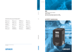
Cat. No. I216E-EN-01 Model: 3G3RX CX-Drive Version: 2.7.0.20 Notice: OMRON products are manufactured for use according to proper procedures by a qualified operator and only for the purposes described in this manual. The following conventions are used to indicate and classify precautions in this manual. Always heed the information provided with them. Failure to heed precautions can result in injury to people or damage to property. OMRON Product References All OMRON products are capitalized in this manual. The word “Unit” is also capitalized when it refers to an OMRON product, regardless of whether or not it appears in the proper name of the product. OMRON, 2013 All rights reserved. No part of this publication may be reproduced, stored in a retrieval system, or transmitted, in any form, or by any means, mechanical, electronic, photocopying, recording, or otherwise, without the prior written permission of OMRON. No patent liability is assumed with respect to the use of the information contained herein. Moreover, because OMRON is constantly striving to improve its high-quality products, the information contained in this manual is subject to change without notice. Every precaution has been taken in the preparation of this manual. Nevertheless, OMRON assumes no responsibility for errors or omissions. Neither is any liability assumed for damages resulting from the use of the information contained in this publication. Pump Sequencer Application Software Read and Understand this Manual Please read and understand this manual before using the product. Please consult your OMRON representative if you have any questions or comments. Warranty and Limitations of Liability WARRANTY OMRON's exclusive warranty is that the products are free from defects in materials and workmanship for a period of one year (or other period if specified) from date of sale by OMRON. OMRON MAKES NO WARRANTY OR REPRESENTATION, EXPRESS OR IMPLIED, REGARDING NON-INFRINGEMENT, MERCHANTABILITY, OR FITNESS FOR PARTICULAR PURPOSE OF THE PRODUCTS. ANY BUYER OR USER ACKNOWLEDGES THAT THE BUYER OR USER ALONE HAS DETERMINED THAT THE PRODUCTS WILL SUITABLY MEET THE REQUIREMENTS OF THEIR INTENDED USE. OMRON DISCLAIMS ALL OTHER WARRANTIES, EXPRESS OR IMPLIED. LIMITATIONS OF LIABILITY OMRON SHALL NOT BE RESPONSIBLE FOR SPECIAL, INDIRECT, OR CONSEQUENTIAL DAMAGES, LOSS OF PROFITS OR COMMERCIAL LOSS IN ANY WAY CONNECTED WITH THE PRODUCTS, WHETHER SUCH CLAIM IS BASED ON CONTRACT, WARRANTY, NEGLIGENCE, OR STRICT LIABILITY. In no event shall the responsibility of OMRON for any act exceed the individual price of the product on which liability is asserted. IN NO EVENT SHALL OMRON BE RESPONSIBLE FOR WARRANTY, REPAIR, OR OTHER CLAIMS REGARDING THE PRODUCTS UNLESS OMRON'S ANALYSIS CONFIRMS THAT THE PRODUCTS WERE PROPERLY HANDLED, STORED, INSTALLED, AND MAINTAINED AND NOT SUBJECT TO CONTAMINATION, ABUSE, MISUSE, OR INAPPROPRIATE MODIFICATION OR REPAIR. Pump Sequencer Application Software 1 Pump Sequencer Application Software Application Considerations SUITABILITY FOR USE OMRON shall not be responsible for conformity with any standards, codes, or regulations that apply to the combination of products in the customer's application or use of the products. At the customer's request, OMRON will provide applicable third party certification documents identifying ratings and limitations of use that apply to the products. This information by itself is not sufficient for a complete determination of the suitability of the products in combination with the end product, machine, system, or other application or use. The following are some examples of applications for which particular attention must be given. This is not intended to be an exhaustive list of all possible uses of the products, nor is it intended to imply that the uses listed may be suitable for the products: • Outdoor use, uses involving potential chemical contamination or electrical interference, or conditions or uses not described in this manual. • Nuclear energy control systems, combustion systems, railroad systems, aviation systems, medical equipment, amusement machines, vehicles, safety equipment, and installations subject to separate industry or government regulations. • Systems, machines, and equipment that could present a risk to life or property. Please know and observe all prohibitions of use applicable to the products. NEVER USE THE PRODUCTS FOR AN APPLICATION INVOLVING SERIOUS RISK TO LIFE OR PROPERTY WITHOUT ENSURING THAT THE SYSTEM AS A WHOLE HAS BEEN DESIGNED TO ADDRESS THE RISKS, AND THAT THE OMRON PRODUCTS ARE PROPERLY RATED AND INSTALLED FOR THE INTENDED USE WITHIN THE OVERALL EQUIPMENT OR SYSTEM. PROGRAMMABLE PRODUCTS OMRON shall not be responsible for the user's programming of a programmable product, or any consequence thereof. 2 Pump Sequencer Application Software Disclaimers CHANGE IN SPECIFICATIONS Product specifications and accessories may be changed at any time based on improvements and other reasons. It is our practice to change model numbers when published ratings or features are changed, or when significant construction changes are made. However, some specifications of the products may be changed without any notice. When in doubt, special model numbers may be assigned to fix or establish key specifications for your application on your request. Please consult with your OMRON representative at any time to confirm actual specifications of purchased products. DIMENSIONS AND WEIGHTS Dimensions and weights are nominal and are not to be used for manufacturing purposes, even when tolerances are shown. PERFORMANCE DATA Performance data given in this manual is provided as a guide for the user in determining suitability and does not constitute a warranty. It may represent the result of OMRON's test conditions, and the users must correlate it to actual application requirements. Actual performance is subject to the OMRON Warranty and Limitations of Liability. ERRORS AND OMISSIONS The information in this manual has been carefully checked and is believed to be accurate; however, no responsibility is assumed for clerical, typographical, or proofreading errors, or omissions. Pump Sequencer Application Software 3 Pump Sequencer Application Software Safety Precautions • Indications and meanings of safety information In this user's manual, the following precautions and signal words are used to provide information to ensure the safe use of the RX Inverter. The information provided here is vital to safety. Strictly observe the precautions provided. • Meanings of signal words DANGER Indicates an imminently hazardous situation which, if not avoided, is likely to result in serious injury or may result in death. Additionally there may be severe property damage. CAUTION Indicates a potentially hazardous situation which, if not avoided, may result in minor or moderate injury or in property damage. • Alert symbols in this document DANGER Turn off the power supply and implement wiring correctly. Not doing so may result in a serious injury due to an electric shock. Wiring work must be carried out only by qualified personnel. Not doing so may result in a serious injury due to an electric shock. Do not change wiring and slide switches (SW1), put on or take off Digital Operator and optional devices, replace cooling fans while the input power is being supplied. Doing so may result in a serious injury due to an electric shock. Be sure to ground the unit. Not doing so may result in a serious injury due to an electric shock or fire. (200-V class: type-D grounding, 400-V class: type-C grounding) Do not remove the terminal block cover during the power supply and 10 minutes after the power shutoff. Doing so may result in a serious injury due to an electric shock. Do not operate the Digital Operator or switches with wet hands. Doing so may result in a serious injury due to an electric shock. Inspection of the Inverter must be conducted after the power supply has been turned off. Not doing so may result in a serious injury due to an electric shock. The main power supply is not necessarily shut off even if the emergency shutoff function is activated. 4 Pump Sequencer Application Software CAUTION Do not connect resistors to the terminals (PD/+1, P/+, N/-) directly. Doing so might result in a small-scale fire, heat generation or damage to the unit. Install a stop motion device to ensure safety. Not doing so might result in a minor injury. (A holding brake is not a stop motion device designed to ensure safety.) Be sure to use a specified type of braking resistor/regenerative braking unit. In case of a braking resistor, install a thermal relay that monitors the temperature of the resistor. Not doing so might result in a moderate burn due to the heat generated in the braking resistor/regenerative braking unit. Configure a sequence that enables the Inverter power to turn off when unusual overheating is detected in the braking resistor/ regenerative braking unit. The Inverter has high voltage parts inside which, if short-circuited, might cause damage to itself or other property. Place covers on the openings or take other precautions to make sure that no metal objects such as cutting bits or lead wire scraps go inside when installing and wiring. Do not touch the Inverter fins, braking resistors and the motor, which become too hot during the power supply and for some time after the power shutoff. Doing so may result in a burn. Take safety precautions such as setting up a molded-case circuit breaker (MCCB) that matches the Inverter capacity on the power supply side. Not doing so might result in damage to property due to the short circuit of the load. Do not dismantle, repair or modify this product. Doing so may result in an injury. Pump Sequencer Application Software 5 Pump Sequencer Application Software Precautions for Safe Use • Installation and storage Do not store or use the product in the following places. •Locations subject to direct sunlight. •Locations subject to ambient temperature exceeding the specifications. •Locations subject to relative humidity exceeding the specifications. •Locations subject to condensation due to severe temperature fluctuations. •Locations subject to corrosive or flammable gases. •Locations subject to exposure to combustibles. •Locations subject to dust (especially iron dust) or salts. •Locations subject to exposure to water, oil, or chemicals. •Locations subject to shock or vibration. • Transporting, installation and wiring •Do not drop or apply strong impact on the product. Doing so may result in damaged parts or malfunction. •Do not hold by the front cover and terminal block cover, but hold by the fins during transportation. •Do not connect an AC power supply voltage to the control input/output terminals. Doing so may result in damage to the product. •Be sure to tighten the screws on the terminal block securely. Wiring work must be done after installing the unit body. •Do not connect any load other than a three-phase inductive motor to the U, V, and W output terminals. •Take sufficient shielding measures when using the product in the following locations. Not doing so may result in damage to the product. Locations subject to static electricity or other forms of noise. Locations subject to strong magnetic fields. Locations close to power lines. • Operation and adjustment •Be sure to confirm the permissible range of motors and machines before operation because the inverter speed can be changed easily from low to high. •Provide a separate holding brake if necessary. •If the Drive Programming stops during multi-function output, the output status is held. Take safety precautions such as stopping peripheral devices. •If the clock command is used in Drive Programming, an unexpected operation may occur due to weak battery. Take measures such as detecting a weak battery by a check that the clock data returns to the initial setting and stopping the inverter or programs. When the LCD Digital Operator is removed or disconnected, Drive Programming is in a waiting status by the clock command. • Maintenance and Inspection •Be sure to confirm safety before conducting maintenance, inspection or parts replacement. •The capacitor service life is influenced by the ambient temperature. Refer to “Smoothing Capacitor Life Curve” described in the manual. When a capacitor reaches the end of its service life and does not work as the product, you need to replace the capacitor. •When disposing of LCD digital operators and wasted batteries, follow the applicable ordinances of your local government. When disposing of the battery, insulate it using tape. The following display must be indicated when products using lithium primary batteries (with more than 6 ppb of perchlorate) are transport to or through the State of California, USA. Perchlorate Material - special handling may apply. See www.dtsc.ca.gov/hazardouswaste/perchlorate The 3G3AX-OP05 has the lithium primary battery (with more than 6 ppb of perchlorate). Label or mark the above display on the exterior of all outer shipping packages of your products when exporting your products which the 3G3AX-OP05 are installed to the State of California, USA. 6 Pump Sequencer Application Software •Do not short + and –, charge, disassemble, heat, put into the fire, or apply strong impact on the battery. The battery may leak, explode, produce heat or fire. Never use the battery which was applied strong impact due to such as fall on the floor, it may leak. •UL standards establish that the battery shall be replaced by an expert engineer. The expert engineer must be in charge of the replacement and also replace the battery according to the method described in this manual. •When the display of LCD Digital Operator can not be recognized due to the service life, replace the LCD Digital Operator. Precautions for Correct Use • Installation •Mount the product vertically on a wall with the product's longer sides upright. The material of the wall has to be noninflammable such as a metal plate. • Main circuit power supply •Confirm that the rated input voltage of the Inverter is the same as AC power supply voltage. • Error Retry Function •Do not come close to the machine when using the error retry function because the machine may abruptly start when stopped by an alarm. •Be sure to confirm the RUN signal is turned off before resetting the alarm because the machine may abruptly start. • Non-stop function at momentary power interruption •Do not come close to the machine when selecting restart in the non-stop function at momentary power interruption selection (b050) because the machine may abruptly start after the power is turned on. • Operation stop command •Provide a separate emergency stop switch because the STOP key on the Digital Operator is valid only when function settings are performed. •When checking a signal during the power supply and the voltage is erroneously applied to the control input terminals, the motor may start abruptly. Be sure to confirm safety before checking a signal. • Product Disposal •Comply with the local ordinance and regulations when disposing of the product. Pump Sequencer Application Software 7 Pump Sequencer Application Software Warning labels Warning labels are located on the inverter as shown in the following illustration. Be sure to follow the instructions. :$51,1* /2&$/ 5(027( 5($' :5,7( (6& ):' 5(9 Warning description 8 Pump Sequencer Application Software Checking Before Unpacking • Checking the product •On delivery, be sure to check that the delivered product is the Inverter 3G3RX model that you ordered. Should you find any problems with the product, immediately contact your nearest local sales representative or OMRON sales office. • Checking the nameplate 3G3RX-A2004-E1F 1(;;; • Checking the model 3 G 3 R X -A 2 0 5 5 - E F F: Built-in filter E: Europe standard Max. applicable motor capacity 004 007 015 022 037 040 055 075 110 150 0.4 kW 0.75 kW 1.5 kW 2.2 kW 3.7 kW 4.0 kW 5.5 kW 7.5 kW 11 kW 15 kW 185 220 300 370 450 550 750 900 11K 13K 18.5 kW 22 kW 30 kW 37 kW 45 kW 55 kW 75 kW 90 kW 110 kW 132 kW Voltage class 2 4 3-phase 200 V AC (200-V class) 3-phase 400 V AC (400-V class) Enclosure rating Pump Sequencer Application Software A Panel-mounting (IP20 min.) or closed wall-mounting models B IP00 9 Pump Sequencer Application Software Revision History •A manual revision code appears as a suffix to the catalogue number located at the lower left of the front and back covers. Cat. No. I216E-EN-01 Revision code Revision code Revision date 01 November 2013 Description Original production Related Manuals Cat. No. I560-E2 I130E-EN 10 Description RX User’s Manual RX Quick Start Guide I579-E2 LCD Digital Operator User’s Manual I580-E2 MX2/RX/LX Drive Programming User’s Manual Pump Sequencer Application Software Pump Sequencer Application Software 1 OVERVIEW ........................................................................................................... 13 1.1 1.2 1.3 1.4 1.5 Introduction .................................................................................................................................................. Handling of this user’s manual ..................................................................................................................... Safety instruction .......................................................................................................................................... Current problem/solution ............................................................................................................................. Features of the application software ............................................................................................................. 13 13 13 13 13 2 PREPARATION AND SYSTEM CONFIGURATION .............................................. 14 2.1 Installation and power circuits ..................................................................................................................... 14 2.2 Connection diagram ..................................................................................................................................... 15 3 APPLICATION CONFIGURATION STEPS ........................................................... 16 3.1 Parameter settings and Drive Programming application ........................................................................... 16 4 PUMP SEQUENCER APPLICATION FUNCTIONS ............................................... 22 4.1 4.2 4.3 4.4 4.5 4.6 Setting fix pumps number 22 ............................................................................................................................ PID regulation adjustment ........................................................................................................................... 22 Pump sequencer auxiliary START diagram ................................................................................................ 23 Pump sequencer auxiliary STOP diagram .................................................................................................. 24 Sleep function ................................................................................................................................................ 25 Disconnection detection ............................................................................................................................... 26 5 DRIVE PROGRAMMING PARAMETERS ............................................................. 27 5.1 5.2 5.3 5.4 5.5 Application software parameters ................................................................................................................. 27 Inputs/outputs ............................................................................................................................................... 28 Monitor parameters ...................................................................................................................................... 28 Error codes 28 .................................................................................................................................................... Other relevant parameters ........................................................................................................................... 29 Pump Sequencer Application Software 11 12 Pump Sequencer Application Software Pump Sequencer Application Software 1 OVERVIEW 1.1 Introduction This user’s manual explains how to use the Pump Sequencer Application program for 3G3RX inverter. Be sure to read this user’s manual carefully before using this Pump Sequencer Application program, and keep it on hand for further reference. Traditionally, pump systems when reaching certain capacity require splitting the pump unit of big capacity into smaller one. Then it is a simple way to keep pressure in the circuit within certain limits in steps, just starting and stopping this pumps, thus saving energy as the flow demand variation is big and not all the pumps are required all the time... With the introduction of Variable Speed Drives the technology allowed continuous and smooth control through closed loop pressure sensor PID control loop. This provide the best circuit response and implemented means of reducing the stress in the piping system when pumps were directly started. 1.2 Handling of this user’s manual The contents of this user’s manual are subject to change without prior notice. No part of this user’s manual may be reproduced in any form without the publisher’s permission. If you find any incorrect description, missing description or have questions concerning the contents of this user’s manual, please contact the publisher. 1.3 Safety instruction Be sure to read this user’s manual, inverter user’s manual, and appended documents thoroughly before using Pump Sequencer Application program and the inverter. Ensure you to understand and follow all safety information, precautions, and operating and handling instructions for the correct use of the inverter. Always use the inverter strictly within the range of specifications described in the inverter user’s manual and correctly implement maintenance and inspection to prevent fault from occurring. When using the inverter together with optional products, also read the manual of those products. Note that this user’s manual and the manual for each optional product to be used should be delivered to the end user of the inverter. In this user’s manual you can find WARNING along the instruction WARNINGS: indicates that incorrect handling may cause hazardous situation, which may result in serious personal injury or death. 1.4 Current problem / solution When it comes to big capacity pumping, using a unique big pump and inverter for smooth control becomes too expensive solution... Then a hybrid solution of a modulated pump and several auxiliary fixed speed pumps with intelligent sequencing controller was found to be an optimal solution... 1.5 Features of the application software Pump sequencer software provides within the inverter logic functionalities to control a system of pumps where one pump is being controlled in speed and others are started and stopped by system pressure demand and conditions... The pressure in the system is closed-loop controlled and advanced PID controller also integrated in the inverter. The herewith presented case software implements both PID regulation and multiple configurable slave pumps handling, to provide a compact and flexible solution for pump control systems. The software described in this document allows the control of a system of up to 4 auxiliary pumps. We have following pump functionality: All in one: Inverter houses all control. Physical units: Set Point and Present value readout in %. Modulated pump control: • Starting and stopping configurable conditions from feedback pressure reading, output frequency and auxiliary pump status. • Minimum and maximum speed for controlled pump modeling. • Advanced PID control. Auxiliary pumps control: • Definable amount and control of auxiliary pumps up to 4 with RX inverter. • Starting and Stop conditions based on modulated pump output. Pressure/flow/level feedback signal: 0-10 V sensor, 0-20 mA, 4-20 mA. Pump Sequencer Application Software 13 Pump Sequencer Application Software Modulated pump automatic frequency drop/rise (water hammer effect cancellation): At startup/stop of auxiliary pump with configurable conditions. This compensates the peak of pressure appearing when a fixed speed pump is activated. Automatic auxiliary pumps: The auxiliary pumps with less running time will be started first. Duty cycle for each pump can be 100% or 50%, which means a pump with 50% duty will work half the time of others. Specific faults and alarms: • Break: Feedback sensor breakdown fault. • Feedback limit alarms (Hi, Lo faults). Pump working time totalizers: Individual for each pump and inverter. Test operation: In this mode it is possible to manually control the start/stop of auxiliary fix pumps for test purposes. 2 PREPARATION AND SYSTEM CONFIGURATION To prepare the inverters for operation, the configuration tool CX-Drive is used for setting parameters and to download the Pump Sequencer Application program. In the following chapters we will show the necessary steps to set up the inverter for a pump sequencer application. We will use 3G3RX inverter. 2.1 Installation and power circuits This manual does not cover how to install the inverters in cabinets, how to wire power supply or how to satisfy other application specific requirements. Please, refer to the RX User’s Manual (I560-E2). 14 Pump Sequencer Application Software PREPARATION AND SYSTEM CONFIGURATION 2.2 Connection diagram Braking resistor (optional) DC reactor (optional) PD/+1 R/L1 3-phase 200 V AC 3-phase 400 V AC To wire the control circuit power supply and main circuit power supply separately, be sure to remove the J51 connector Control circuit wire first. power supply N/– RB U/T1 S/L2 V/T2 T/L3 W/T3 J51 Short-circuit wire P/+ R T AL1 Ro AL2 To AL0 CM1 11 PLC 12 DC24V FW Start pump sequencer 13 1 LoLo 2 HiHi 3 Reset 4 No function 5 No function 6 No function 7 No function 8 14 15 Multi-function output common CM2 Relay output *1 Common KA1 KA2 KA3 Fix pump 1 activation Fix pump 2 activation Fix pump 3 activation KA4 Fix pump 4 activation Not used 24 VDC +/- (External supply) SP SN RP Sequence input common M P24 SN RS485 communication For termination resistors CM1 AM Thermistor TH AMI H 10 VDC PV 0 to 10 V O 10k Analog input terminal O2 Option 1 10k PI 0 to 20 mA PID feedback OI sensor DC10V 100 L *1 FM Pressure set point *1 Option 2 L is the common reference for analog input and also for analog output. Note: RX maximum setting wiring with 4 auxiliary fix pumps. Pump Sequencer Application Software 15 Pump Sequencer Application Software 3 APPLICATION CONFIGURATION STEPS 3.1 Parameter settings and Drive Programming application Follow next steps in order to upload inverter parameter settings with CX-Drive tool, download the pump sequencer application case software and save the project: 1. Open CX-Drive. 2. Connect your computer USB port to the RJ-45 3G3RX inverter port with 3G3AX-PCACN2 cable or USB-CONVERTERCABLE. Remove the LCD Digital Operator to access RJ-45 port: 3. Use the CX-Drive autodetect function in order to go online with the 3G3RX inverter: 4. A new dialog will appear for autodetect function, trying to connect with 3G3RX inverter: 16 Pump Sequencer Application Software APPLICATION CONFIGURATION STEPS 5. After detecting the inverter, automatically a new project will be created (in online mode) in the CX-Drive: 6. Press mouse right button if you want to change the Drive name. A new dialog will appear: 7. Introduce the Drive name and press OK button: Pump Sequencer Application Software 17 Pump Sequencer Application Software 8. The new name will be updated in the project tree: 9. Upload inverter parameters clicking the icon. A new dialog will appear. Select only Drive Parameter and press ok: After pressing ok, the parameters will start to be transferred: Once the parameters have been downloaded, a new message window will appear indicating that parameter have been transferred successfully: 18 Pump Sequencer Application Software APPLICATION CONFIGURATION STEPS 10. Import the Drive Programming case application software. Go to File -> Import: Go to the folder where you have the “.driveprogram” file. Select the file and press Open button: 11. In the project tree go to the section Drive Programming with double-click: Pump Sequencer Application Software 19 Pump Sequencer Application Software 12. Download Drive Programming program by pressing the download icon in the Drive Programming section: A new dialog will appear showing the status of the downloading process: After downloading a new message box will appear indicating that the program has been downloaded with success. Press ok button: 13. After downloading the DP program, press the Start 02: Always ON. program button, or set parameter A017 (Drive programming (EzSQ) selection) to 14. Go to the Status -> Drive Programming section and verify that Tasks are running: Double-click in the Status -> Drive Programming section: Note: This Pump Sequencer software version is using task#1, task#2, task#3 and task#4. So, verify that four tasks are running. 20 Pump Sequencer Application Software APPLICATION CONFIGURATION STEPS 15. Save your project. Go to File -> Save As... option: A new dialog will appear. Put the file name that you want for the project and press the “Save” button: 16. Start with the application configuration and inverter parameter settings. Pump Sequencer Application Software 21 Pump Sequencer Application Software 4 PUMP SEQUENCER APPLICATION FUNCTIONS 4.1 Setting fix pumps number By default settings, the RX pump sequencer could manage up to 4 auxiliary fix pumps. If your pump system needs to work with a less number of auxiliary fix pumps, set the auxiliary fix pumps operation mode that are not needed in the system to value 0 = “Disabled”. The program automatically will reject these auxiliary pumps, and will not be considered in the sequence. Note: Take care what auxiliary fix pump is disabled in the system and verify that the auxiliary fix pumps that are wired in the system, corresponds to your auxiliary fix pumps settings. To select the work mode of each auxiliary fix pump, please refer to the next parameter table: Parameter No. Name Setting range Unit Default setting P100 AuxPump1 mode 0 to 4 - 2 P101 AuxPump2 mode 0 to 4 - 2 P102 AuxPump3 mode 0 to 4 - 2 P103 AuxPump4 mode 0 to 4 - 2 Description 0: “Disabled” 1: “Aux. 50% Duty” 2: “Aux. 100% Duty” 3: “Manual test ON” 4: “Manual test OFF” 0: “Disabled” 1: “Aux. 50% Duty” 2: “Aux. 100% Duty” 3: “Manual test ON” 4: “Manual test OFF” 0: “Disabled” 1: “Aux. 50% Duty” 2: “Aux. 100% Duty” 3: “Manual test ON” 4: “Manual test OFF” 0: “Disabled” 1: “Aux. 50% Duty” 2: “Aux. 100% Duty” 3: “Manual test ON” 4: “Manual test OFF” Mode descriptions: • • • • • Mode 0 = “Disabled”: Setting this operation mode, the auxiliary fix pump will not work in the system. Mode 1 = “Aux. 50% Duty”: Setting this operation mode, the auxiliary fix pump will work at 50% duty cycle. Mode 2 = “Aux. 100% Duty”: Setting this operation mode, the auxiliary fix pump will work at 100% duty cycle. Mode 3 = “Manual test ON”: Setting this operation mode, the auxiliary fix pump will be activated. Mode 4 = “Manual test OFF”: Setting this operation mode, the auxiliary fix pump will be deactivated. 4.2 PID regulation adjustment Parameter list for PID regulation adjustment: Parameter No. A071 A072 A073 A074 A075 A076 A077 A078 A079 C044 C052 C053 Name Setting range Unit PID selection PID P gain PID I gain PID D gain PID scale PID feedback selection Reverse PID function PID variable range limit PID feedforward selection PID deviation excessive level PID FB upper limit PID FB lower limit 0 to 2 0.2 to 5.0 0.0 to 3600.0 0.00 to 100.00 0.01 to 99.99 0 to 10 0 to 1 0.0 to 100.0 0 to 3 0.0 to 100.0 0.0 to 100.0 0.0 to 100.0 sec sec % % - Value 1: Enabled 1.00 1.0 0.0 1.00 0: OI 0: OFF 0.0% 0: Disabled 3.0% 100.0 0.0 Note: For more information, refer to the RX User’s Manual (I560-E2). 22 Pump Sequencer Application Software PUMP SEQUENCER APPLICATION FUNCTIONS 4.3 Pump sequencer auxiliary START diagram Freq A061 ModPmp Upper limit setting P112 Freq Drop @ON P108 Fix Pump On Delay P108 Fix Pump On Delay P110 Change Time A062 ModPmp Lower limit setting P112 Freq Drop @ON P110 Change Time Starting ramp Internal RUN command One Auxiliary Pump Output on-delay time Other Auxiliary Pump Output on-delay time Parameter No. Name Setting range Unit Default setting Description Time delay for started fixed pump in front of modulated pump speed saturation This serves to adapt modulated pump changes to the response times of fixed pumps. It is possible to set transition time for auxiliary pumps ON and OFF To avoid water hammer effect when auxiliary pump goes ON. Decrement of modulated pump frequency on auxiliary pump activation ON delay time for digital output terminal 11 ON delay time for digital output terminal 12 ON delay time for digital output terminal 13 ON delay time for digital output terminal 14 P108 Fix Pump Vlv ON delay 0 to 20000 [0.00 to 200.00 sec] sec 1000 [10.00 sec] P110 Fix Pump Vlv change time 0 to 1000 [0.00 to 10.00 sec] sec 200 [2.00 sec] P112 Frequency drop@ON 0 to 100% % 20% C130 C132 C134 C136 Output 11 ON delay time Output 12 ON delay time Output 13 ON delay time Output 14 ON delay time 0.0 to 100.0 0.0 to 100.0 0.0 to 100.0 0.0 to 100.0 sec sec sec sec 0.0 0.0 0.0 0.0 Pump Sequencer Application Software 23 Pump Sequencer Application Software 4.4 Pump sequencer auxiliary STOP diagram Freq A061 ModPmp Upper limit P110 Change Time P109 Fix Pump Off Delay P111 Freq Boost @OFF A062 ModPmp Lower limit P110 Change Time P109 Fix Pump Off Delay P111 Freq Boost @OFF Internal RUN command One Auxiliary Pump Output off-delay time Other Auxiliary Pump Output off-delay time Parameter No. Name Setting range Unit Default setting Description Time delay for stopping fixed pump in front of modulated pump speed saturation This serves to adapt modulated pump changes to the response times of fixed pumps. It is possible to set transition time for auxiliary pumps ON and OFF To avoid sudden underpressure on system increment of modulated pump frequency when auxiliary pump goes OFF OFF delay time for digital output terminal 11 OFF delay time for digital output terminal 12 OFF delay time for digital output terminal 13 OFF delay time for digital output terminal 14 P109 Fix Pump Vlv OFF delay 0 to 20000 [0.00 to 200.00 sec] sec 1000 [10.00 sec] P110 Fix Pump Vlv change time 0 to 1000 [0.00 to 10.00 sec] sec 200 [2.00 sec] P111 Frequency boost@OFF 0 to 100% % 20% C131 C133 C135 C137 Output 11 OFF delay time Output 12 OFF delay time Output 13 OFF delay time Output 14 OFF delay time 0.0 to 100.0 0.0 to 100.0 0.0 to 100.0 0.0 to 100.0 sec sec sec sec 0.0 0.0 0.0 0.0 24 Pump Sequencer Application Software PUMP SEQUENCER APPLICATION FUNCTIONS 4.5 Sleep function Modulated pump internal run command will shut off, if the output frequency monitor (d001) becomes less than the sleep frequency level (P114), during a specified period (P116). After that, if the PID deviation monitor (d153) exceeds the PID deviation level value (P115), during a specified period (P117), the internal run command will be restarted. PID Sleep Function diagrams d001 - Frequency Monitor P114 - Sleep Frequency level Run Mod Pmp Internal Run Command P116 Delay Time to shut off internal run P115 - PID Deviation level d153 - PID Deviation Monitor Run Mod Pmp Internal Run Command P117 Delay Time to restart internal run Parameter No. Name P114 Sleep frequency level P115 Sleep deviation level P116 Sleep delay time OFF P117 Sleep delay time ON Setting range Unit Default setting Description 0 to max. freq (A004) - 2100 [21.00 Hz] Sleep level default to 21 Hz (recommended setting is a bit higher than the minimum speed of the pump in P108) 0 to 10000 [0.00 to 100.00%] 0 to 1000 [0.00 to 10.00 sec] 0 to 1000 [0.00 to 10.00 sec] % sec sec 200 [2.00%] 500 [5.00 sec] 500 [5.00 sec] Level to restart modulated pump Delay time to put the modulated pump to OFF Delay time to put the modulated pump to ON Caution: Drive Programming PID sleep function is always enabled if the frequency level is different to 0 (P114 <> 0), PID enable parameter is set to 1: Enabling, parameter A156 and A157 are set to 0.0 and Drive Programming program is running (A017 = 2: Always ON). If Drive Programming program is running and parameters A156 (PID sleep function action threshold) and A157 (PID sleep function action delay time) have different values to 0, there will be a DP PID sleep malfunction, so the internal inverter PID sleep function will be running, too. Pump Sequencer Application Software 25 Pump Sequencer Application Software 4.6 Disconnection detection It detects a feedback disconnection when the PID feedback is under the programmed PID disconnection level. Parameter No. Name Setting range Unit Default setting P123 PID feedback disconnection level 0 to 10000 [0.00 to 100.00%] % 500 [5.00%] Description Disconnection level for break sensor detection Note: At first start-up, even if the PID-FB is under the programmed level, no trip will be performed, but, after this first start-up, if PID-FB overpass the programmed level, PID disconnection function will perform a trip if the PID-FB goes under the PID disconnection level (P123). 26 Pump Sequencer Application Software DRIVE PROGRAMMING PARAMETERS 5 DRIVE PROGRAMMING PARAMETERS 5.1 Application software parameters Parameter No. Name Setting range Unit Default setting P100 AuxPump1 mode 0 to 4 - 2 P101 AuxPump2 mode 0 to 4 - 2 P102 AuxPump3 mode 0 to 4 - 2 P103 AuxPump4 mode 0 to 4 - 2 P108 Fix Pump Vlv ON delay P109 Fix Pump Vlv OFF delay P110 Fix Pump Vlv change time P111 0 to 20000 [0.00 to 200.00 sec] 0 to 20000 [0.00 to 200.00 sec] sec sec 1000 [10.00 sec] 1000 [10.00 sec] 0 to 1000 [0.00 to 10.00 sec] sec 200 [2.00 sec] Frequency boost@OFF 0 to 100% % 20% P112 Frequency drop@ON 0 to 100% % 20% P113 Totalizer reset 0 to 1 - 0 P114 Sleep frequency level 0 to max. freq (A004) - 2100 [21.00 Hz] P115 Sleep deviation level P116 Sleep delay time OFF P117 Sleep delay time ON P123 PID feedback disconnection level Pump Sequencer Application Software 0 to 10000 [0.00 to 100.00%] 0 to 1000 [0.00 to 10.00 sec] 0 to 1000 [0.00 to 10.00 sec] 0 to 10000 [0.00 to 100.00%] % sec sec % 200 [2.00%] 500 [5.00 sec] 500 [5.00 sec] 500 [5.00%] Description 0: “Disabled” 1: “Aux. 50% Duty” 2: “Aux. 100% Duty” 3: “Manual test ON” 4: “Manual test OFF” 0: “Disabled” 1: “Aux. 50% Duty” 2: “Aux. 100% Duty” 3: “Manual test ON” 4: “Manual test OFF” 0: “Disabled” 1: “Aux. 50% Duty” 2: “Aux. 100% Duty” 3: “Manual test ON” 4: “Manual test OFF” 0: “Disabled” 1: “Aux. 50% Duty” 2: “Aux. 100% Duty” 3: “Manual test ON” 4: “Manual test OFF” Time delay for started fixed pump in front of modulated pump speed saturation Time delay for stopping fixed pump in front of modulated pump speed saturation This serves to adapt modulated pump changes to the response times of fixed pumps. It is possible to set transition time for auxiliary pumps ON and OFF To avoid sudden underpressure on system increment of modulated pump frequency when auxiliary pump goes OFF To avoid water hammer effect when auxiliary pump goes ON. Decrease of modulated pump frequency on auxiliary pump activation Resets one of the totalizer monitors: 0: No action 1: All reset Once reset is done returns to zero Sleep level default to 21 Hz (recommended setting is a bit higher than the minimum speed of the pump in P108) Level to restart modulated pump Delay time to put the modulated pump to OFF Delay time to put the modulated pump to ON Disconnection level for break sensor detection 27 Pump Sequencer Application Software 5.2 Inputs/outputs Digital inputs Terminal input 1 2 3 4 5 6 7 8 Value C001 = 56: X(00) Drive Programming (MI1) C002 = 57: X(01) Drive Programming (MI2) C003 = 58: X(02) Drive Programming (MI3) C004 = 18: RS (Reset inverter) C005 = 255: No function C006 = 255: No function C007 = 255: No function C008 = 255: No function Description Start/Stop modulated pump and sequence Sensor LoLo: Used for LoLo level or pressure/flow alarm from digital input Sensor HiHi: Used for HiHi level or pressure/flow alarm from digital input Reset inverter Not used Not used Not used Not used Digital outputs Terminal output Value 11 C021 = 44: Y(00) Drive Programming (MO1) 12 C022 = 45: Y(01) Drive Programming (MO2) 13 C023 = 46: Y(02) Drive Programming (MO3) 14 C024 = 47: Y(03) Drive Programming (MO4) 15 C025 = 255: No function AL2, AL1, AL0 C026 = 5: AL (Alarm output) Description PumpSeq 1 out: Output for the aux. fix pump 1 PumpSeq 2 out: Output for the aux. fix pump 2 PumpSeq3 out: Output for the aux. fix pump 3 PumpSeq4 out: Output for the aux. fix pump 4 Not used Inverter alarm output Analog inputs With parameter A076 - PID feedback selection it’s possible to select which analog input will be the PID feedback sensor for the PID inverter function. Pump sequencer use the inverter default setting: Terminal input Value O Voltage analog input OI Current analog input Description Pressure set point PID feedback sensor 5.3 Monitor parameters Parameter No. Name d004 PID feedback value monitor d016 Total RUN time d153 PID deviation monitor P104 Aux Pump1 run time P105 Aux Pump2 run time P106 Aux Pump3 run time P107 Aux Pump4 run time Unit Description PID feedback monitor Hours Totalizer of running time for main pump PID deviation monitor Totalizer of running time for auxiliary pump 1 Hours This is also used for pump rotation Totalizer of running time for auxiliary pump 2 Hours This is also used for pump rotation Totalizer of running time for auxiliary pump 3 Hours This is also used for pump rotation Totalizer of running time for auxiliary pump 4 Hours This is also used for pump rotation 5.4 Error codes Error 28 Name E51 LoLo (Sensor LoLo fault) E52 HiHi (Sensor HiHi fault) E53 Break (Fbck sensor break) Description From digital input limit. The system will go to FAULT state, stopping all operation From digital input limit. The system will go to FAULT state, stopping all operation Indicates broken sensor condition. The system will go to FAULT state, stopping all operation Pump Sequencer Application Software DRIVE PROGRAMMING PARAMETERS 5.5 Other relevant parameters Parameter No. Name F002 Acceleration time 1 F003 Deceleration time 1 A001 Frequency reference selection A002 Run command selection A004 Maximum frequency A017 Drive Programming (EzSQ) selection A044 V/F characteristics selection A051 DC injection braking selection A061 Frequency upper limit A062 Frequency lower limit A071 PID selection A072 PID P gain A073 PID I gain A074 PID D gain A075 PID scale A076 PID feedback selection A077 Reverse PID function A078 PID output limit function A079 PID feedforward selection A097 Acceleration pattern selection A098 Deceleration pattern setting A901 Insertion point b001 Retry selection b008 Trip retry selection Electronic thermal characteristics selecb013 tion b035 Rotation direction limit selection b049 Dual rate selection Analog operation level at O disconnecb070 tion Analog operation level at OI disconnecb071 tion b082 Starting frequency b088 Free-run stop selection Overvoltage protection function selecb130 tion during deceleration C052 PID FB upper limit C053 PID FB lower limit C091 Debug mode selection C102 Reset selection C103 Reset frequency matching selection Setting range 0.01 to 3600.00 sec 0.01 to 3600.00 sec 0 to 10 1 to 5 50.0 to 400.0 Hz 0 to 2 0 to 5 0 to 2 0 to max. frequency 0 to A061 0 to 2 0.2 to 5.0 0.0 to 3600.0 0.00 to 100.00 0.01 to 99.99 0 to 10 0 to 1 0.0 to 100.0% 0 to 3 0 to 4 0 to 4 0 to 1 0 to 4 0 to 4 Value 10.00 sec 10.00 sec 1: Terminal 1: Terminal 50.0 Hz 2: Always ON 1: VP (special reduced torque characteristics) 0: Disabled 50.0 Hz 20.0 Hz 1: Enabled 1.00 1.0 0.00 1.00 0: OI 0: OFF 0.0% 0: Disabled 1: S-curve 1: S-curve 1: Enabled 0: Trip (Alarm) 0: Trip (Alarm) 0 to 2 0: Reduced torque characteristic 0 to 2 0 to 1 0: Forward and reverse are enabled 1: ND (normal duty) 0 to 255 255 0 to 255 255 0.10 to 9.99 0 to 2 0.50 0: 0 Hz start 0 to 2 0: Disabled 0.0 to 100.0 0.0 to 100.0 0 to 1 0 to 3 0 to 2 100.0 0.0 1: MD1 (enabled) 0: Trip reset at power-on 0: 0 Hz start Note: Verify that parameter A901 (Insertion point) is enabled before starting the application. Pump Sequencer Application Software 29 Pump Sequencer Application Software 30 Pump Sequencer Application Software Authorized Distributor: Cat. No. I216E-EN-01 Note: Specifications subject to change without notice. Printed in Europe