1
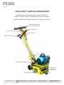
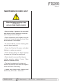
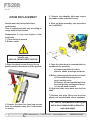
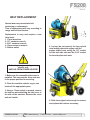
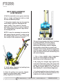
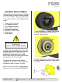
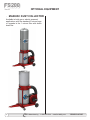
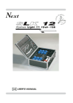
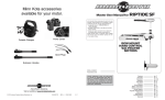
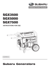
FS200D Electric
Portable Deluxe Scarifier
User Manual
MANUFACTURING
Cutters / Removers / Parts / Support
(954) 941-9744
www.SMITHMFG .com
1-800-653-9311
www.SmithMfg.com
Phone: 954-941-9744 • Fax: 954-545-0348
FS200
Electric
INTRODUCTION
Congratulations on purchasing
the FS200™ Surface Preparator from
SMITH Mfg. Company.
INDEX
Page
Contents
2
Index / Introduction
3
Safety Guidelines
4
Your FS200 Surface Preparator
5
Machine Start-Up
6
Substrate Removal
7
Storage, Ordering, and Warranty Claims
8
Troubleshooting
9
Maintenance Check List
10
Drum Replacement
11-12 Belt Replacement and Alignment
13-14 Bearing Replacement
15-16
Optional Equipment
17-18 Maintenance Log
19
Limited Equipment Warranty
20
Warranty Activation
Your machine will:
• Clean surfaces impacted by grease, oil,
plastics, tars, resins, tile adhesives, ice and
more
• Plane or mill asphalt and concrete surfaces
• Remove high spots in curbs and gutters
• Eliminate trip-hazards on concrete sidewalks
• Mill areas for rumble strips
• Clean out cracks and joints
• Create anti-slip patterns in walkways and barns
• Prepare surfaces for new coating applications
• Permanently remove all road and surface
coatings to include:
epoxy, urethane, thermoplastic, paint,
glue-backed tapes and more...
• Groove-inlay asphalt for striping
• Groove-inlay asphalt for stiping
• Prepare surface prior to “Hot Tape”
applications
BEFORE START-UP,
READ THIS..
Please read all operating instructions, including
the provided engine manual and be completely
familiar with your equipment before operating.
When in doubt, please contact SMITH
Manufacturing Customer Service for operational
details. This Owner’s Manual will guide you
through the removal process, from start to finish,
and show you how to care for your machine.
2
SMITH Manufacturing
1-954-941-9744
www.SmithMfg.com
VERSION 8/2013
FS200
Electric
UNCRATING EQUIPMENT
When you uncrate your equipment, make certain
that the machine has not been damaged and
that all fasteners and guards are properly
tightened.
Your machine may not have been shipped
assembled with cutters and other accessories.
Assembly may be required.
REMEMBER: Only authorized, experienced and
properly trained personnel should operate this
equipment. Operating personnel should practice
safety at all times and wear protective gear
(gloves, goggles, safety vests, ear plugs, steeltoe shoes, etc.)
SAFETY GUIDELINES
• Do not operate the machine in an explosive
atmosphere, near combustible materials, or
when gas fumes may not be properly dispersed
• Never leave the machine unattended when
running, and you must hold onto the handle with
two hands when the cutter drum is engaged
DAILY CHECKLIST
• Check all electrical components to ensure they
are not damaged
• Ensure that all guards are in place before the
machine is operated, since torating and moving
parts willl cause injury upon contact.
• Check and replace (as needed)
*Cutters
*Bearings *Shafts
*Drive shaft *Dust flap *Wheels
• Check that all fasteners are secure
• Check that all controls and safety devices are
functioning properly
Incorrect use of the surface preparator
can result in property damage, personal
injury, or death. Be sure to read and
follow all directions and precautions as
outlined in this manual.
OPERATION
• Get acquainted with the controls
• Always wear protective equipment, including
ear protection, breathing apparatus, steel-toed
shoes, and goggles
• Never wear baggy or loose fitting clothing that
can be caught on controls or moving parts
• The surface preparator can emit flying
particles and debris during operation. Never
operate the machine near bystanders, animals
or children
VERSION 8/2013
SMITH Manufacturing
1-954-941-9744
www.SmithMfg.com
3
FS200
Electric
YOUR FS200TM SURFACE PREPARATOR
Please take time to familiarize yourself with the FS200™’s
controls, as well as some of the features of your new machine.
Read the engine manual before preparing the engine for starting.
Height adjuustable T-handle
w. vibration reducing grips
Depth control lever
Locking knob (T-hanle)
On/Off Switch
Micro-depth control knob
Plug
Fixed front wheel assembly
Feathering front
swivel wheel
assembly
Removable Side Plate
4
SMITH Manufacturing
1-954-941-9744
www.SmithMfg.com
VERSION 8/2013
FS200
Electric
MACHINE START-UP
Do not start machine while drum is in
contact with the ground. Doing so can
cause the operator to lose control of the
machine, resulting in property damage
and/or personal injury.
Before starting the machine, make sure that
all cables are clear and undamaged.
Before substrate removal, test run the drum
with cutters not touching the surface. If there
is excessive vibration, you need to re-balance
the cutter set-up, check bearing condition,
and/or make sure that the drive shaft is
secured.
VERSION 8/2013
SMITH Manufacturing
1-954-941-9744
www.SmithMfg.com
5
FS200
Electric
SUBSTRATE REMOVAL
Adjust the height of the cutter drum with the
depth control lever. Set the deoth of cut to
allow the cutters to go through only the
materials to be removed. Make certain that
the drum is positioned to where only the
cutters strike the surface, and that the drum
assembly never comes into contact with the
substrate. The cutter tips alone should
strike the surface (1/8” to 1/4” maximum
depth per removal pass on new cutters).
TIP: Positioning the machine over the
surface in many directions, as well as
dialing the hand wheel up or down can help
create desirable surface patterns.
After several hours of practice, the operator
will become comfortable and should be able
to remove materials faster with enhanced
results.
When the job is completed, or the operator
wants to cease work, stop the engine by first
lifting the drum above the substrate using the
hand-wheel and/or the cam lever. Stop the
machine only at the engine. Then close the
fuel cock to shut off the fuel supply.
The drum will not withstand substrate
contact. Contacting the removal surface
too deeply will cause premature wear to
cutters, shafts, drum and other
components! TIP: The correct depth
setting is indicated by relatively little
machine vibration.
The drum assembly must be removed daily
and inspected for drum wear, hole
elongation and possible weld separation.
Replace the cutter shafts and drum bushings
every 40 hours, or prior to any drum wear. If
the drum’s center holes are elongated, order
another SMITH cutter drum.
Too much downward pressure only has
negative results. Try to remove materials in
several passes rather than one, deep pass.
Several tests will show the best, most
appropriate cutter impact. Use a forward,
backward and/or circular pattern to achieve
your desired finish.
NOTE: Only use a forward motion when the
CM2519 or CM2535 carbide scraping cutters
are used.
6
SMITH Manufacturing
1-954-941-9744
www.SmithMfg.com
VERSION 8/2013
FS200
Electric
STORAGE
WARRANTY CLAIMS
• Shut off fuel and siphon all excess fuel.
• Start engine and run until it stalls.
• Remove the spark plug and pour two ounces
of motor oil into cylinder and slowly crank the
engine to distribute oil to prevent rust during
storage.
• Replace spark plug and store machine upright
in a cool, dry, and well ventilated area.
The manufacturer reserves the right to
change or improve the machine design
without assuming any obligation to update
any products previously manufactured
before this manual. It is the customer’s
responibility to complete the warranty card
and mail it to the seller within 10 days from
date of purchase. If a failure occurs during
the warranty period, the customer must
contact the seller to determine the
appropriate action.
ORDERING
To ensure product safety and reliability,
and to maintain your warranty, always use
genuine replacement cutters and partsfrom
SMITH when making repairs to equipment.
Any and all transportation charges are to
be borne by the purchaser.
When ordering please specify the model and
serial number of the machine. In addition, give
a part number, description, and quantity as
listed on your parts list.
If you have any questions about the operation
of your machine or would like to order
replacement parts, contact your SMITH
Manufacturing representative directly.
Contact 1-800-653-9311 (954-941-9744)
for information.
Visit our website at
www.smithmfg.com
VERSION 8/2013
SMITH Manufacturing
1-954-941-9744
www.SmithMfg.com
7
FS200
Electric
TROUBLESHOOTING
MACHINE JUMPS
ERRATICALLY
PROBLEM
Drum hitting ground
RPM is too low
Surface is severely uneven
Possible Reason(s)/Solution(s)
DRIVE BELT WEARING
PREMATURELY
CUTTERS WEARING
UNEVENLY/PREMATURELY
Pulley is misaligned
Wrong belt
Drum is contacting
the surface
Drum is too low
Incorrect set-up
Material Build-up
Cutters too tightly loaded
Wrong cutters for
application
DEPTH CONTROL LEVER IS
SET TOO LOW
CUTTERS SHAFT BREAKAGE
UNEVENLY/PREMATURELY
Adjust the height of lever
UNEVEN CUTTING
Drum is too low
End plates or bushings worn
Shafts worn
Wrong cutter set-up
Cutting too deeply
Rear wheel fork is bent
For any other problems or questions,
please contact your local representative
or
SMITH Mfg today at 800-653-9311
or
(954) 941-9744.
DRUM WEARING
PREMATURELY OR CRACKING
Drum hitting ground
Shafts and bushings not replaced
in time
EXCESS VIBRATION
Bearing worn
Hex bushing worn
Drive shaft worn
Improper cutter set-up
Drum contacting ground
*Engine repair and engine warranty
issues are handled directly
by your local engine service center.
Wheels worn out
8
SMITH Manufacturing
1-954-941-9744
www.SmithMfg.com
VERSION 8/2013
FS200
Electric
MAINTENANCE CHECK LIST
Before beginning servicing on any
electric unit,
UNPLUG FROM POWER SOURCE!
• Keep a coating of grease on the drive shaft
and threads for easy installation or removal,
and for longer hex bushing life.
• Check all fasteners and re-tighten, since the
machine will vibrate the fasteners loose if they
are not secured. Use locktight.
• All three hex Bolts on drum retaining plate
must be aligned and tight.
• Check the Drive belt for wear, and adjust
(tighten), or replace as required.
• Check that the pulleys are aligned properly
to ensure the Drive belt is running true.
• Check wheel for wear and that they are
rotating properly, replace if worn. Clean
wheels of material build-up.
• The inside housing must be clean, and
remove any build-up from inside the cage so
cutters and drum rotate freely.
• Inspect and change drum bushings and
shafts every 40 hours, or when worn.
VERSION 8/2013
SMITH Manufacturing
1-954-941-9744
www.SmithMfg.com
9
FS200
Electric
DRUM REPLACEMENT
3. Remove the sideplate (this may require
the rubber mallet to break it loose)
Normal wear may necessitate drum
replacement.
Time of replacement will vary according to
usage and belt load factors.
4. Slide out drum assembly. (use precaution
as it is HEAVY)
Replacement is easy and requires a few
hand tools.
1. 17mm socket or wrench
2. Rubber mallet
4)
Before beginning servicing on any
electric unit,
UNPLUG FROM POWER SOURCE!
3)
2)
1. Raise the depth control lever to the up
position so the cutter drum is off the ground.
5. Once the cutter drum is removed take to a
workbench for assembly.
a) Inspect condition of cutters,
spacers, shafts, bushings and drum.
6) Before replacing the drum onto hex shaft:
a) Check that all bearings are in
good working order
b) Remove dirt and material build-up
from inside drive carriage and drum.
c) Lube all metal contacts
6) Align and slide drum back onto the hex
shaft.
1)
7) Replace side plate (lift-up and lock into
place) over hex shaft and secure hardware.
2. Remove the three hex head cap screws
from the sideplate using the 17mm socket
or wrench.
10
SMITH Manufacturing
*TIP: SMITH recommends owning an
extra drum loaded with cutters for
rapid job-sight
1-954-941-9744
www.SmithMfg.com
VERSION 8/2013
FS200
Electric
BELT REPLACEMENT
Normal wear may necessitate belt
tensioning or replacement.
Time of replacement will vary according to
usage and belt load factors.
3)
Replacement is easy and requires a few
hand tools.
1. 17mm wrenches
2. 1/2” socket or wrench
3. 9/16” socket or wrench
4. 13mm socket or wrench
5. Rubber mallet
4. Loosen (do not remove) the four nylock
nuts locking down the engine until the
engine slides freely using the 1/2” socket
for the belt side nuts and the 9/16” socket
for the side plate side nuts
Before beginning servicing on any
electric unit,
UNPLUG FROM POWER SOURCE!
4)
1. Make sure the removable side cover is
installed. This ensures the drive ends are
in the proper position for servicing.
2. Clean the machine exterior so you can
locate all the appropriate parts.
3. Using a 17mm socket or wrench, remove
the two hex nuts attaching the belt cover to
the side of the machine. Remove the cover
and set it aside.
5. Slide the engine back enough to remove
and replace the belts as necessary.
VERSION 8/2013
SMITH Manufacturing
1-954-941-9744
www.SmithMfg.com
11
FS200
Electric
BELT REPLACEMENT
(CONTINUED)
6. Roll the new belt on one groove at a time
(two or single multi-groove belt) on both
the top and bottom pulleys.
7. Using the straight edge, lay it across the
lower pulley outer face and against the
upper pulley. They must be directly
over top of each other to ensure long belt
life. If adjustment is required, align before
tensioning the belt.
NOTE: It may be necessary to remove the
belt guard support bracket in order to get
the straight edge flush on the pulleys. Do
this using a 13mm socket or wrench.
BELT ALIGNMENT
If the unit has premature belt wear, breakage
or pulley problems, the issue may be
incorrect alignment or excessive belt
tensioning. All pulleys must be aligned
directly above each other to ensure belt
integrity. This includes possible timing belts
used on newer models. Incorrect alignment
wears the sides of the belts excessively and
will cause slippage.
7)
1. Use a long straight edge (carpenters
square) to check alignment during belt
tensioning or belt replacement time.
8. Verify pulley alignment by looking from
the front of the machine.
9. Once the pulleys are properly aligned,
tighten everything down and re-check
pulley alignment one last time.
12
SMITH Manufacturing
2. By laying the straight edge against the
outer face of the lower pulley, the square will
extend up and rest against the outer face of
the upper (engine pulley). If not, move the
motor pulley in or out to obtain alignment.
3. If replacing pulleys (top or bottom) be sure
to place the pulley on the same plane as the
original one to ensure alignment.
1-954-941-9744
www.SmithMfg.com
VERSION 8/2013
FS200
Electric
BEARING REPLACEMENT
Before reading ahead go back and follow
the instructions on how to remove the belt
from the machine. Bearing replacement
is easy and requires a few addtional hand
tools.
1. 16mm socket or wrench
2. 1/2” socket or wrench
3. 9/16” socket or wrench
4. 13mm socket or wrench
4. Flat head screw driver
5. Hammer or rubber mallet
6. 6mm hex key
7. Circlip pliers
2) CLOCKWISE
TO LOOSEN
1)
3. Once the pulley is removed, the bearing
assembly on that side can be removed
using the 6mm hex key.
3)
Before beginning servicing on any
electric unit,
UNPLUG FROM POWER SOURCE!
1. Follow the instructions to remove the
drum and belts from the machine, leave the
sideplate aside to remove the bearing
housing later. Remove the lower pulley
using a scew driver to flatten out the tabs
securing the lock nut to the shaft.
2. Remove the lock nut on the shaft by
putting the screw driver on one of the tabs
and hittting it with a hammer or mallet.
NOTE: the lock nut is LEFT HAND threads
therefore it must be rotated CLOCKWISE to
VERSION 8/2013
SMITH Manufacturing
4. At this point remove the bearing housing
from the sideplate using the 13mm socket
or wrench
4)
1-954-941-9744
www.SmithMfg.com
13
FS200
Electric
BEARING REPLACEMENT
(CONTINUED)
7. The side plate side bearing assembly
(clear zinc plated) is shown below.
5. Once both bearing housings are removed,
the circlip pliers will be needed to remove
the snap rings and a block of wood or something similar to knock the bearings out of
the housing.
6. The BELT SIDE bearing assembly (yellow
zinc plated) is shown below.
14
SMITH Manufacturing
1-954-941-9744
***WARNING***
When pressing bearings in,
use a soft wooden dowel and
only apply pressure to the
outter race of the bearings
www.SmithMfg.com
VERSION 8/2013
OPTIONAL EQUIPMENT
•
EDGER DRUM ASSEMBLY
Available for diamomd blades and cutter
applications
VERSION 8/2013
SMITH Manufacturing
•
FS200
Electric
WATER CONTROLS
Used to extend life on diamond drum
applications and for dust control on all others
1-954-941-9744
www.SmithMfg.com
15
FS200
Electric
OPTIONAL EQUIPMENT
• MAXIVAC DUST COLLECTOR
Available in both gas or electric powered
applications with the standard 5 micron bags
or upgrade to the 1 micron filter with shake
down bar
16
SMITH Manufacturing
1-954-941-9744
www.SmithMfg.com
VERSION 8/2013
MAINTENANCE LOG
FS200
Electric
VERSION 8/2013
SMITH Manufacturing
1-954-941-9744
www.SmithMfg.com
17
FS200
Electric
MAINTENANCE LOG
WARRANTY CLAIMS
The manufacturer reserves the right to change or improve the machine design without assuming any
obligation to update any products previously manufactured before this manual. It is the customer’s
responsibility to complete the warranty card and mail it to the seller within 10 days from the date
of purchase. If a failure occurs during the warranty period, the customer must contact the seller
to determine the appropriate action. Any and all transportation charges are to be borne by the
purchaser.
18
SMITH Manufacturing
1-954-941-9744
www.SmithMfg.com
VERSION 8/2013
Limited Equipment Warranty
FS200
Electric
All statements, technical information and recommendations contained in SMITH’s literature are based on tests believed to be reliable, but the accuracy
or completeness thereof is not guaranteed and the following is made in lieu of all warranties, expressed or implied. SMITH warrants all equipment or part
referenced in this document which is manufactured by SMITH and bearing its name to be free from defects in material and workmanship on the date of
sale to the original purchaser under normal use and maintenance as herein provided. This warranty does not apply to components manufactured by others
such as, but not limited to, bearings and engines; such components that may or may not have their own warranties.
With the exception of any special, extended, or limited warranty published by SMITH, SMITH will, for a period of three months (90 days) from the
date of sale or up to five hundred (500) hours of use by buyer, whichever shall occur first; repair or replace any part of the equipment determined by
SMITH to be defective. This warranty applies only when the equipment or part is installed, operated and maintained in accordance with SMITH’s written
recommendations.
SMITH’s sole obligation for any breach of warranty or breach of contract for defects, deliberate or accidental omissions, shall be limited to repairing,
replacing or allowing credit for, at SMITH’s option, any part which, under normal and proper use and maintenance, proves defective in material or
workmanship within warranty period, provided, however, that notice of any such defect or omission and satisfactory proof thereof is promptly given by
buyer to SMITH, and thereafter, such defective part is returned to SMITH with transportation charges prepaid, and SMITH’s examination proves such part
to have been defective. This warranty does not obligate SMITH to bear any transportation charges or personnel time in connection with the replacement
or repair of defective parts. This warranty does not obligate SMITH to bear any expense for travel time or of personnel in connection with any service calls.
SMITH will not, in any event, be liable to the user for any consequential damages arising out of this sale for the loss of use, lost profits or revenue, interest,
lost goodwill or work stoppage. SMITH shall not be liable for any injury, loss or damage, direct or consequential, arising out of the use or the inability to use
the product or for environmental claims. It being understood that SMITH has no means of controlling the products final use; therefore, it shall be buyer’s
responsibility to determine suitability of product for intended use and buyer assumes all risks and liabilities whatsoever, in connection therewith. In no event
shall SMITH be liable for consequential or special damages. Used products are sold on an “as is” basis, and there is no implied warranty of merchantability
or of fitness for a particular purpose, unless made in writing by an officer at SMITH’s office.
This warranty does not cover, and SMITH shall not be liable for general wear and tear, or any malfunction, damage or wear caused by faulty installation,
misapplication, abrasion, corrosion, inadequate or improper maintenance, negligence, accident, tampering, or substitution of non-SMITH component parts.
Nor shall SMITH be liable for malfunction, damage or wear caused by the incompatibility of SMITH equipment with structures, accessories, equipment
or materials not supplied by SMITH, or the improper design, manufacture, installation, operation or maintenance of structures, accessories, equipment
or materials not supplied by SMITH. This warranty does not apply in respect to damages to any product or accessory or attachment thereof caused by
overloading or other misuse, neglect or accident, nor does this warranty apply to any product or accessory or attachment thereof, which has been repaired
or altered in any way which, in the sole judgment of SMITH, affects the performance, stability or general purpose for which it was manufactured. In the
manufacture of buyer’s equipment, parts may be omitted or equivalent functioning equipment and components may be substituted for the original specified
equipment upon the sole judgment and discretion of SMITH.
This warranty is conditioned upon the prepaid return of the equipment claimed to be defective to an authorized SMITH Reseller for verification of the
claimed defect. If the claimed defect is verified, SMITH will repair or replace free of charge any defective parts and return of merchandise back to the
customer freight collect. If inspection of the equipment does not disclose any defect in material or workmanship, repairs will be made at a reasonable
charge, which charges may include the costs of parts, labor and transportation.
THIS WARRANTY IS EXCLUSIVE AND IS IN LIEU OF ANY OTHER WARRANTIES, EXPRESS OR IMPLIED, INCLUDING BUT NOT LIMITED TO
WARRANTY OF MERCHANTABILITY OR WARRANTY OF FITNESS FOR A PARTICULAR PURPOSE.
SMITH’s sole obligation and buyer’s sole remedy for any breach of warranty shall be as set forth above. The buyer agrees that no other remedy (including,
but not limited to, incidental or consequential damages for lost profits, lost sales, injury to person or property, or any other incidental or consequential loss)
shall be available. Any action for breach of warranty must be brought within two (2) years of the date of sale.
SMITH MAKES NO WARRANTY, AND DISCLAIMS ALL IMPLIED WARRANTIES OF MERCHANTABILITY AND FITNESS FOR A PARTICULAR
PURPOSE, IN CONNECTION WITH ACCESSORIES, EQUIPMENT, MATERIALS OR COMPONENTS SOLD BUT NOT MANUFACTURED BY SMITH.
These items sold, but not manufactured by SMITH (such as electric motors, switches, hose, etc.), are subject to the warranty, if any, of their manufacturer.
SMITH will provide purchaser with reasonable assistance in making any claim for breach of these warranties. In no event will SMITH be liable for indirect,
incidental, special or consequential damages resulting from SMITH supplying equipment hereunder, or the furnishing, performance, or use of any products
or other goods sold hereto, whether due to a breach of contract, breach of warranty, the negligence of SMITH, or otherwise.
ADDITIONAL WARRANTY COVERAGE - SMITH does provide extended warranty and wear warranty for products.
Corrections - typographical or clerical errors contained herein are subject to correction by SMITH.
Assignment - buyer shall not assign or transfer this warranty without SMITH’s written consent.
Entire agreement and applicable law - the rights and obligations of SMITH and buyer shall be governed by the laws of the state of Florida, U.S.A. In force
on date hereof. The provisions hereof are intended by buyer and SMITH as a final expression of their agreement, and are intended also, as a complete
and exclusive statement of all terms apply cable to buyer’s order. No waiver, modification, or addition to any of the terms hereof shall be binding on SMITH,
unless made in writing by an officer at SMITH’s office as stated herein. In the event of conflict between buyer’s purchase order and the terms hereof, the
latter shall control. If any provisions herein are to any extent invalid or unenforceable, the remainder of the warranty shall not be effected thereby and shall
be valid and enforceable to the fullest extent permitted by law.
Legal action - buyer shall be responsible for all costs of collection of outstanding indebtedness, including but not limited to attorney’s fees and court costs
to seller. Buyer shall reimburse seller for any and all litigation expenses seller incurs as a result of an unsuccessful buyer claim. The jurisdiction and venue
of the court for any litigation, state or federal, brought by the buyer and/or seller shall be located in venue determined by seller.
Fair labor standards - seller’s products are produced in the United States and in conformity with all applicable provisions of the fair labor standards act of
1938 as amended and any regulations and orders of the United States Department of Labor issued thereunder.
All written and visual data contained in this document reflects the most current product information available at the time of this publication. SMITH reserves
the right to make changes at any time without notice.
TO ORDER, contact your SMITH distributor or call 1-800-653-9311 to identify the nearest distributor.
SMITH Manufacturing Co, Inc.
1610 South Dixie Highway
Pompano Beach, FL 33060
www.smithmfg.com
VERSION 8/2013
SMITH Manufacturing
1-954-941-9744
www.SmithMfg.com
19
FS200
Electric
Pre-Operation Inspection - Warranty Activation - Machine Registration
Go to www.smithmfg.com/warranty_activation.php
Thank you for purchasing a SMITH. This machine was tested and passed inspection prior to shipping.
Please complete this form upon receipt of your equipment and prior to use on the job. Failure to do so will void warranty.
All sections must be completed. Should you have any questions, please add to the comments section below.
Fax completed form to (954) 545-0348 or email to [email protected]
**Do not contact SMITH for engine/motor problems, only machine warranty issues **
Motor/Engine Warranty Contacts: Honda: http://engines.honda.com/dealer-locator/
Subaru: http://robinamerica.com/dealerusacan.aspx
Leeson: http://www.leeson.com/leeson/servicecenter.do?invoke=viewServiceCenterLocator
Brook Crompton Motor: http://www.brookcromptonna.com/contact.html
Weg Motors: http://www.weg.net/us/Contact/Service-Network
Purchaser Details
Organization ___________________________________________________________________________
Name ___________________________________
Title: ______________________________
Operators: _______________________________________________________________________
Phone:
______________________________________
Email: ___________________________________
Address ______________________________________________________________________________
City ___________________________________________
State _____________ Zip ________________
FS200 Electric
SMITH Machine _____________________________
Machine Serial # _____________________________
Date of Purchase ____________
Purchased from______________________________
Pre-Operation Inspection (Please check all)
1. No parts or components on the machine appear damaged or lost in shipment. [ ] Yes [ ] No
2. All bolts, fasteners, hoses are in place and tightly secured, wheels are operational.
[ ] Yes [ ] No
3. Grease points have been identified for future maintenance requirements and appear lubricated. [ ] Yes [ ] No
4. Cutters and Drum/Spindle Assembly are operational and secure on machine. [ ] Yes [ ] No
5. Motor has been started and in good working condition. [ ] Yes [ ] No
6. All Decals appear in place and securely attached. [ ] Yes [ ] No
7. Equipment runs and tested to assure all components are operating correctly. [ ] Yes [ ] No
8. Do you have a Wear Parts Kit with an Extra Cutter set in stock? [ ] Yes [ ] No
9. Did you join Remove Faster News for tech updates, experience sharing and special offers? [ ] Yes [ ] No
10. Comments: ________________________________________________________________________________
_____________________________________________________________________________________________
_____________________________________________________________________________________________
Inspector’s Signature: ___________________________________ Date: _____________________
Note: To prevent downtime, experienced users stock (1) machine wear parts kit with an extra cutter drum/spindle assembly
& (1) cutter drum/spindle rebuild kit after receipt. Do you want to purchase and receive a special offer? [ ] Yes [ ] No
20
SMITH Manufacturing
1-954-941-9744
www.SmithMfg.com
VERSION 8/2013
MANUFACTURING
Cutters / Removers / Parts / Support
(954) 941-9744
www.SMITHMFG .com
SMITH Manufacturing
1610 South Dixie Highway
Pompano Beach, FL 33060
Toll Free: 800.653.9311
Phone: 954.941.9744
Fax: 954.545.0348
Email: [email protected]
www.SmithMfg.com