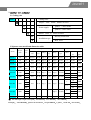
1
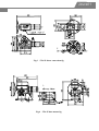
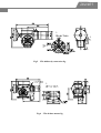
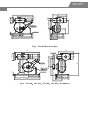
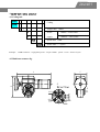
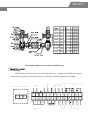
Jewett Electrical Actuator User Manual Jewett Jewett Index 1. General description ...............................................................................................................2 1.1 Application....................................................................................................................................... 2 1.2 Techincal feature ............................................................................................................................. 2 1.3 Structure feature ............................................................................................................................. 2 1.4 Diagrams .......................................................................................................................................... 3 2. Quarter-turn electrical actuator ..................................................................................................................... 4 2.1 Coding rules ..................................................................................................................................... 4 2.2 Model & dimension ......................................................................................................................... 4 3. Linear electrical actuator.....................................................................................................11 3.1 Coding rule..................................................................................................................................... 11 3.2 Out feature ..................................................................................................................................... 11 3.3 Model & paramenter .................................................................................................................... 12 4. Multi-turn electrical actuator ..............................................................................................13 4.1 Coding rule..................................................................................................................................... 13 4.2 Out feature ..................................................................................................................................... 13 4.3 Dimensions and installation.......................................................................................................... 14 4.4 Model serials .................................................................................................................................. 14 5. Operation manual................................................................................................................15 5.1 Connecting ........................................................................................................................................ 15 5.2 Setting................................................................................................................................................ 16 5.3 Password ........................................................................................................................................... 16 5.5 Parameter setting ............................................................................................................................. 17 5.6 Installation and trouble shooting .................................................................................................... 20 Jewett 1. General description 1.1 Application The JT serial created the absolute new ideal for the actuator which is the essential module of the industrial automation system, it integrated with the MCU , hardware and software together to meet the smart control of the actuators, it accept the control signals from regulators/DCS/PC to respond in action accordingly. It could be applied in the on/off control and regulation control for the valve and fume duct in the industries such as power plant, metallurgy, chemistry, cement and water treatment, with high reliability and various choices on specification, function, accuracy, flexibility & easiness for installation and hook-up. 1.2 Technical feature LCD display with back lighting,smart setting for the terminal parameters Control signal:4~20mACompatible with Remote integral on/off input Position feedback:4~20mA RL:500Ω High reliability by insulation between the control signal input, valve position feedback and the MCU module, no additional insulator needed. Multi-protection for over torque, open circuit, motor over heat, software range setting(details see manual) Self-diagnostic Power:3 Phases 380V(4 lines)~50Hz ;Single Phase 220V~50Hz Ambient temperature: -30~70℃ IP65 , meet IEC145 Relative Humidity: 85%, no erotic gas 1.3 Structure feature The electrical actuator includes the motor, gear box, stroke switch, torque protection, servo module, smart setting panel etc. 1.3.1 The motor provides the force to the actuator,it divides into single phase and 3 phases asynchronous motor。It features high initial torque, low start current and less inertia, it also has heat sensitive switch inside which may active. To enhance the reliability of the actuator, JT series actuator do not adopt the mechanical stopper system, but with electrical stopping module. 1.3.2 The retarder divides into 3 stage(Multi-turn only have 2 stages),the 1st and 2nd stage utilize the small dimension/high ratio/high efficiency galaxy gear box, and the final sage utilize the high decreasing ratio/self-locked cam screw,in case of linear actuator, the cam Jewett screw transfer to linear motion, and in case of quarter turn actuator, the cam screw transfer into angle motion. 1.3.3 The limit switch helps get into preliminary protection program with 2 cam blocks at the end of both directions. The cam blocks are drove by speed-down module, the stroke range may be adjustable by modify the location of the cam block. 1.3.4 The torque limit switch module is configured with the sensor connected to the spring which pressed by the paddle connected to the galaxy wheels, it will be activated only if the springs is out of its torque limitation, and the micro-motion switch will be trigged, the force limitation on the spring is adjustable. Once the stroke limitation module or the torque limitation module were trigged, theactuator could only turn in reverse direction. 1.3.5 Integrated servo module includes the power, CPU, drive module, position detector, which is the core part of the actuator, its quality truly effected the smooth running of the actuator. JT series actuator was processed, assembled and test under strict quality control. 1.3.6 The setting panel is used for parameters setting function, it’s for tuning and test only as an option which may be plugged off after test. One setting panel could be sufficient for test several actuator, it could provide smart setting and solution for failures. The LCD screen used to monitor the running status(input/feedback) and could be used for check the error information with trouble shooting function. 1.4 Servo module schematics. Torque stroke lim it Logical protection Sw itching input Analog input O utput indicator CPU Current convert Pow er drive Heat sensitive sw itch M otor Angle sensor Retarder Valve 注:analog or switching input were selected on the control panel, the switching mode is activated when it is shorted, and it also could be used as remote control. Jewett 2. Quarter turn actuator 2.1 Coding rule Coding rules: JTA□ Torque,Unit:10Nm,details see below / S Power supply T 1phase ~220V/50Hz 3phases~380V/50Hz Stroke,Unit:S,details see below □ D B Installation type Directly connection Base fixed 2.2Quarter turn model and dimension table Model Torque Time (Nm) (S) Flange Flange Φ ISO mm Shape Base Weight Kg Shape Power Ball type Phase PowerK R-speed W rpm JTA-10 100 25 F05/F07 Φ20 Fig.1 7.2 Fig.2 RG-10 S,T 0.025 1400 JTA-25 250 30 F10 Φ28 Fig.3 29 Fig.4 RG-25 S,T 0.065 1400 JTA-60 600 30 F14 Φ35 Fig 5 48 Fig.6 RG-60 S,T 0.16 1400 JTA-100 1000 30 48* F12 Φ45 Fig. 7 64 Fig.9 RG-100 S,T 0.25 1400 JTA-160 1600 F14 Φ60 Fig.7 113 Fig.9 RG-160 T 0.4 S,T 0.25 JTA-250 2500 F16 Φ70 Fig.7 143 Fig.9 RG-250 T 0.65 S,T 0.4 28 40 28 40 28 JTA-400 4000 40* 65 T F16 Φ70 Fig.7 145 Fig.9 RG-400 S,T 105 40 JTA-600 6000 65 Fig.8 RG-600 105 JTA-800 10000 105 Fig.9 RG-800 T 1.0 0.65 1400 1400 1400 0.4 1400 0.4 950 1.0 0.65 S,T 0.4 0.65 T 1.0 1400 1400 注:JTA-600 torque output varies from,0°5000Nm, 45°4000Nm, 90°6000Nm。 Example: JTA-100/S30B,quarter turn actuator,torque 1000Nm,1 phase,stroke 30s,base mount。 Jewett F 4-M8 22 Φ50 F05 4-M6 F Φ70 F07 Fig.1 JTA-10 Direct connection A A Fig.2 JTA-10 Base mount Jewett K 2 ×PG16 K Fig.3 JTA-25 direct connection fig. A A Fig.4 JTA-25 base mount fig. Jewett A A 70 30 Fig.5 JTA-60directly connection fig. A A Fig.6 JTA-60 base mount fig. Jewett C ΦA4 D A A ΦA1 E ΦA2 ΦA3 B 148 F A 4-M Fig.7 JTA-100,JTA-160,JTA-250,JTA-400 directly connection fig. JTA-100,JTA-160,JTA-250,JTA-400 actuator(direct connected)dimension table Model ISO A B C D E Key Slot Depth F JTA-100 F12 265 408 275 520 14JS9 50 JTA-160 F14 290 372 Flange JTA-250 JTA-400 F16 395 440 491 18JS9 361 612 20JS9 80 ΦA2 ΦA3 M ΦA4 Φ45E8 Φ125 Φ85 M12 160 Φ60E8 Φ140 Φ100 M16 175 Φ70E8 Φ165 Φ130 M20 250 ΦA1 Jewett 361 580 211 390 96 267 622 350 Φ250 34 20 4-Φ 22 180 100 108 260 320 480 540 216 Fig.8 JTA-600 Base fixed shape H2 H3 H1 C Φ L1 D1 D Φ250 E A5 4-Φ L2 B1 B2 A1 A2 A3 A4 F2 Fig.9 JTA-100,JTA-160,JTA-250,JTA-400,JTA-800 base Jewett JTA-100,JTA-160,JTA-250,JTA-400,JTA-800 actuator(base-mount)dimension table Model A1 A2 A3 A4 A5 JTA-100 240 280 150 190 12 JTA-160 375 435 175 235 JTA-250 JTA-400 500 560 180 240 18 B1 225 B2 45 87 C D1/D 170 200/250 240 97 230 JTA-800 630 700 250 320 40 365 160 370 E F1 F2 28 40 131 450 510 295 400 178 517 30 34 40 50 C1 C ΦA R Fig.10 170 184 80 B No. 1 2 3 4 5 6 7 8 H1 Model JTA-10 JTA-25 JTA-60 JTA-100 JTA-160 JTA-250,400 JTA-600 JTA-800 H2 Arm L C/C1 100 100 160 250/200 250/200 250/200 350 400 ΦL1 ΦL2 2-Φ20 580 602 230 1050 H3 361 2-Φ30 612 ΦA Φ10H10 Φ18H11 Φ20H11 Φ20H10 Φ20H11 Φ30H11 Φ36H10 Φ40H11 quarter turn actuator arm connection dimension fig. Φ17 Φ22 Φ40 Φ32 B 17 22 25 28 30 34 34 40 R R20 R20 R20 R22 R25 R30 R30 R35 Jewett 3. Linear electrical actuator 3.1 Coding rule Coding JTV□ Torqu unit:100Nm / S Power Single phase~220V/50Hz T supply Three phases~380V/50Hz Speed unit:mm/S □□ □□ Stroke unit:mm Example:ModelJTV-64/S1260,linear actuator,single phase,torque6400N,rotation speed1.2mm/sec,stroke 16mm 3.2 Linear electrical actuator fig. B 45° F 41 A A D3 60° 30° 30° D2 K D2 45° D1 H D3 D1 25 A C A 60° Jewett 3.3 Linear actuator model and parameter Model 1phase 220V 3Phases 380V Load Stroke Speed Connection Flange Flange Connection Diameter N mm mm/S JTV-64/T0610 JTV-64/S1210 JTV-64/T1210 JTV-64/S0616 JTV-64/T0616 JTV-64/S1216 JTV-64/T1216 JTV-64/S1816 JTV-64/T1816 1.8 JTV-64/S0625 JTV-64/T0625 0.6 JTV-64/S1225 JTV-64/T1225 JTV-64/S1825 JTV-64/T1825 1.8 JTV-64/S0640 JTV-64/T0640 0.6 JTV-64/S1240 JTV-64/T1240 JTV-64/S1840 JTV-64/T1840 JTV-64/S1260 JTV-64/T1260 JTV-64/S1860 JTV-64/T1860 JTV-100/S0616 JTV-100/T0616 JTV-100/S0625 JTV-100/T0625 JTV-100/S1225 JTV-100/T1225 JTV-100/S1825 JTV-100/T1825 JTV-100/K0640 JTV-100/T0640 JTV-100/S1240 JTV-100/F1240 JTV-100/S1840 JTV-100/T1840 JTV-100/S1260 JTV-100/T1260 JTV-100/S1860 JTV-100/T1860 JTV-160/S1225 JTV-160/T1225 JTV-160/S1240 JTV-160/T1240 JTV-160/S1840 JTV-160/T1840 JTV-160/S1260 JTV-160/T1260 JTV-160/S1860 JTV-160/T1860 JTV-160/S1200 JTV-160/T1200 JTV-160/S1800 JTV-160/T1800 JTV-250/S1240 JTV-250/T1240 JTV-250/S1840 JTV-250/T1840 JTV-250/S1260 JTV-250/T1260 JTV-250/S1860 JTV-250/T1860 JTV-250/S1200 JTV-250/T1200 JTV-250/S1800 JTV-250/T1800 1.2 0.6 16 6400 25 40 D1 Hole D2 D3 A B H K max C 0.6 JTV-64/S0610 10 F Inner M8×1.25 Φ80 1.2 Φ 2HoleΦ11 480 407 91 20 60D11 1.2 M12×1.25 Φ135 Φ 80D11 550 460 146 25 1.2 1.8 60 16 1.2 591 460 168 30 1.8 4HoleΦ11 0.6 0.6 25 1.2 1.8 10000 0.6 40 125 480 480 Φ M16×1.5 Φ118 95D11 25 40 16000 60 100 40 25000 60 100 159 550 480 1.2 168 1.8 60 280 1.2 591 480 1.8 1.2 480 480 1.2 1.8 1.2 M20×1.5 Φ135 1.8 Φ 100D11 1.2 1.2 1.2 1.8 234 600 1.8 1.8 550 480 591 480 1.8 1.2 6HoleΦ18 38 M27×2 Φ135 Φ 100D11 6HoleΦ18 879 600 600 380 Jewett 4. Multi-turn valve actuator 4.1 Coding rule JTMA- Coding JTMB- □ Torque unit:10Nm / S Power 1 Phase~220V/50Hz T supply 3 Phases~380V/50Hz Speed unit:r/min □□ □□ Stroke unit:r(cycle) Example: JTMB-15/S1316,single phase power,torque:150Nm,speed:13r/m,stroke:16 cycle 4.2 Multi-turn actuator fig. A F B ΦI A A H C ΦD4 ΦD2 4-ΦD1 ΦD3 Jewett 4.3 Mutlti-turn dimension and installation Model A Multi-turn B Multi-turn Flange A B C H ΦD1 ΦD2 ΦI ΦD3 ΦD4 F F8 440 336 31.3 6N9 M10 Φ85 Φ165 Φ70fb Φ20 65 350 F14 612 360 38.3 8N9 M 16 Φ140 Φ250 Φ100fb Φ28 81 375 4.4 Multi-turn series Model 1 Phase220V 3Phases380V JTMA-4/S04 JTMA-4/T04 JTMA-4/S10 JTMA-4/T10 JTMA-4/S17 JTMA-4/T17 JTMA-6/S03 JTMA-6/T03 JTMA-6/S05 JTMA-6/T05 JTMA-6/S10 JTMA-6/T10 JTMA-6/T17 JTMA-10/S03 JTMA-10/T03 JTMA-10/S05 JTMA-10/T05 JTMA-6/T10 JTMA-16/S03 JTMA-16/T03 JTMA-16/T05 JTMB-4/S19 JTMB-6/S13 JTMB-6/S19 JTMB-6/T19 JTMB-10/S07 JTMB-10/S13 JTMB-10/T13 JTMB-10/T19 JTMB-16/S04 JTMB-16/S07 JTMB-16/T07 JTMB-16/T13 JTMB-16/T19 JTMB-25/S02 JTMB-25/S04 JTMB-25/T04 JTMB-25/T07 Load Nm 40 60 100 160 40 60 100 160 250 Speed r/min 4.8 9.6 17.5 3.3 4.8 9.6 17.5 3.3 4.8 9.6 3.3 4.8 18.8 13 18.8 7 13 18.8 4.4 7 13 18.8 2.3 4.4 7 Strike r(Cycles) 5,7 10,16 17.5,26 3.3,5 5,7 10,14 17.5,26 3.3,5 5,7 10,14 3.3,5 5,7 15,22.5,34.5,50 15,22.5,34.5,50 8.5,15,22.5,34.5,50 15,22.5,34.5,50 5,7.5,11.5,17.5 8.5,15,22.5,34.5,50 15,22.5,34.5,50 3,5,7.5,11.5,17.5 5,7.5,11.5,17.5 3.5,15,22.5,34.5,50 Jewett ΦD Nm D H L A1 100 0~70 10 15 36 29 RG-25 250 0~70 18 22 41 39 RG-60 600 0~100 18 25 41 45 RG-100 1000 L H RG-10 0~130 20 28 44 50 25° 0~150 20 30 51 50 1600 A1 RG-160 RG-250/400 4000 0~150 30 34 61 65 RG-600 6000 0~150 36 34 61 72 RG-800 8000 0~150 40 40 Base mount quarter turn actuator installation fig. 5. Operation manual 5.1 Connecting All the inner connection have been done before delivery,customer may finish the external connection as fig below. Be careful, the power should be off when connection is making。 Stroke/torque 1-way stroke/torque VSS LMT-2 TMP- TMP+ IO- IO+ VO- VO+ + Input Output 1~5V LMT-1 5V - Output 4~20mA 20mA OUT-O + Input 1~5V OUT-C IN- + Input 4~20mA OUT W1 Open Close R W0 relay common N W2 Motor F Position Potential meter Remote input t UP E DW Stroke/torque protection error signal Over Temp Protection Relay output Close N L GND A/M Open ~ 380V W Remote V N Common U A B L Motor For 3 phases motor only Motor common Motor ~ 220V Valve feedback Jewett Terminal descriptions terminal symbol description terminal symbol description Motor temp. switch ( Motor) temp. switch ( ) Stroke switch-2(Off) A12 IO+ 4-20mA current feedback output + B14 TMP+ A11 IO- 4-20mA current feedback output - B13 TMP- A9 20mA 4-20mA current control - B12 LMT_2 A8 IN- controls signal - B11 Vss A7 W1 potential meter _1 B10 LMT_1 Stroke switch d Stroke switch-1(On) A6 W0 B9 OUT_O Relay constant open A5 W2 potential meter_ l potential meter_2 B8 OUT_C Relay constant close A4 UP remote control_ UP B7 OUT A3 DW remote control_ DOWN B6 R AC 220V motor reverse A2 A/M auto/manual switch B5 N AC 220V motor neutral A1 GND ground B4 F AC 220Vmotor forward B3 E ground B2 N AC 220V zero B1 L AC 220V fire Relay common Note:The remote control has higher priority than the automatic control, when the control A1 and A2 connected, the auto control was blocked, it only accept the pulse signal to order the valve to open or close. 5.2 Control panel The LCD screen with back light is used to monitor the input signal and the valve position. In case of error,push→button to check the error information.。 There are 5 LED indicator,RUN:blink in running and constant light on when error;MANU:manual mode or remote control;AUTO:auto running;R:forward, light on when motion is making;F:reverse,light on when motion is making; 5 push bottons,SET:setting the parameters and used as enter;M/A:manual/auto shift;→button:go right;↑button;up or open valve manually;↓button: down,close the valve manually. If the SET button or →button was hold more than 3 seconds, it works as reset function, if want to escape during the setting, you may use it like this way. 5.3 Password setting:(default 555) Push the M/A button to go into manual mode, then push the set button,display the Jewett SET A,pushe the SET again,display SET B、 SET C;Push the M/A button when the menu is displayed, then you will see the password 555,use →button to move, use ↑↓to modify. If the password setting is finished, then push the SET button. If you want to return during the setting, please push the M/A button to modify. Setting menu A:655 Setting menu B:556 Setting menu C:factory setting, could not modify by the user. 5.4 Error list:in case of error, the light will turn on, push→button to check the error information as below. error beep LCD display 1 Motor blocked 4 beeps Error: Stop Run 2 Out range of input signal 3 beeps Error: Over Flow 3 Open circuit of input signal 2 beeps Error: Offline 4 Over temperature 1 beep Error: HighTmp 5.5 Parameter setting(must be done in the manual mode) ¾ Menu A, by control panel 1)choice for input signal,(default is 4~20mA) A1. Input Signal Type: [4-20mA] 2)idle time from reverse motion 0-9 A2.Brk Spac Time(×50ms): (default 5) [5] 3)decimal digits for open percentage(default 1,Max 2) A3. Decimal Digits: [1] 4)control mode(the control reaction of 4~20mA) (default is positive),if it is negative mode, that means 4mA is open and the 20mA is close. A4. Control Mode: [Action] React 5)setting for blocking(default 0.2%),in case of blocking,will test the potential meter. A5. Stop Check Setup (%) : [0.2] 6)Analog output of the valve position, 4~20mA(default is positive) ,in case of negative,the clockwise means close in stead of open in the quarter turn actuator. Jewett A6. Output Action: [Action] React 7)motion range(between two terminal points), mechanical zero point setting,is reached during the manual mode, it is also limited by the soft limits in the setting, we may reach the mechanical zero point manually, and will remember this point automatically. When you push →button, you will see the current measurement data( last zero point setting), and adjust by push ↑↓ button, and confirm by push the SET button. A7. Machine Origin Setup(L): [0001] 8)Mechanical range between 2 terminal during manually operation, including the soft limit and remote control. With button pushed, it could reach mechanical full open, and record this data. If push →,it will show the current data(last full open data) ,use ↑↓to adjust the valve position, and push SET to confirm. A8. Machine Full Setup(H): [1003] 9)Soft zero limit setting(default:1.0 ) A9. Soft Bounds Origin (%): [1.0] 10)Soft full limit setting (default:99.0) A10. Soft Bounds Full (%): [99.0] 11)Electrical brake time scale, N x 10ms,leveled from0-9 (default: 5),0 means no brake. A11. Brake Time (x10ms): [5] 12)Sensitivity control, (0.01mA-2.00 mA,default:0.1 mA) A12. Sensitive: (0.01-2mA) 0.1 13)valve block tolerance time setting(0-30sec,default:6sec),it means that if there is no feedback after the setting time that input signal sent, it will alarm the valve blocked and enter into pre-setting(details see Menu B). A13. Stop Rotate: Time(<30s) [6] Notice:If the actuator with the clutch, please do not operate the clutch during the running to let the motor rotate without the loader that the feedback will not be synchronized and it will be regarded as an error, and it will need manually reset to restore. 14)Input signal down limit(default 3.5~20.5 mA,range:0~4 mA) A14. Input Range (0-4mA): 3.5 15)Input signal up limit(default:3.5~20.5 mA,range:0~25 mA) A15. Input Range (20-25mA): 20.5 Jewett 16)When the input signal out of the range, it will jump to pre-setting(Menu B), and alarm. A16. Input Over Enable: [Not] / Yes If choose NOT, the actuator does not make any action and keep current position, once the error is solved the actuator will restore automatically. If choose YES, it will enter into pre-setting program.(thereafter same) 17) If the input signal interrupted during the running(=0), the instruction to do(Default: Not, means no output,keep current position and alarm,it will restore automatically once the trouble solved.;If set as Yes,enter into pre-setting(Menu B) and show alarm. A17. Input Offlin Enable: [Not] / Yes 18)Once the motor is over temperature, the instruction to do(default: Not,alarm the contact error, no further action and keep current position,once the temperature low down it will restore automatically. If choose Yes to enter into pre-setting value(Menu B) and show over temperature alarm. A18. Motor T-Over Enable: [Not] / Yes END,show serial number,setting is ended. A19. Serial No: 040901 Software setting(Menu B) 1)Pre-setting value for input out of range,open degree(0~100%,default:50,select Menu B4 3& 4) B1. Input Over Preset: 50% 2)Pre-setting value for input signal interrupted,open degree(0~100%,default 50,select Menu B5 2&3) B2. Input Offline Preset: 50% 3)Valve block solution(default:“1”,stop control output,send contact alarm,it need manually restore after the trouble solved). It could be restore automatically if it is cause by the mechanical stroke or torque switch after which they are solved. It could running in reverse direction once the stroke or torque switch was trigged. B3. Stop Rotate Premod(2): 1 4)Pre-solution for input signal out of range(default“1”,open to soft fully open,stop output, output contact error,manually reset after trouble solved. if“2”,restore automatically after trouble solved.(signal restore and not bigger than the set value as in Menu A-15) if “3”,output contact error, open to designed position(Menu B.1),manually restore after trouble solved. If “4”,output Jewett contact error,open to designed position(Menu B.1),restore automatically once signal is OK. B4. Input Over Premod(4): 1 6)Pre-solution for signal interrupt(default:“1”,no output,keep position,alarm,manually resetafter trouble solved. if“2”,output contact error,and open to pre-set open degree(Menu B2), manually reset after trouble solved. If“3”,output contact error,open to pre-set open degree(Menu B2),automatically restore once the signal restored(Menu A14&15). B5. Input Offline Premod(3): 1 7)pre-solution for over temperature with the motor(default:“1”,alarm contact error,no further output, keep current position,need manually reset after restore. If “2” , alarm contact error, output control signal,restore automatically after temperature low down. If “3”, alarm contact error,output control signal, manually reset is needed after restore.) B6. Motor T-Over Premod(3): 1 8)setting ended 5.6 Installation First of all, please check all the model/range time/torque/power spec could meet the demands. If quarter turn actuator, please rotate the hand wheel to see it the angel is enough, if not please change the position and fasten the screws, then re-check it.(for the arm angel is less than 120°) If the linear actuator mounted on the valve, rotate the hand wheel to see if the actuator stroke smoothly support with the valve, or it will damage the valve. Once the stroke range and angel is defined, it need to adjust the range limit. First, open the control box, put out the PCB, use screw driver to adjust the cam wheel (3#,4#, the start and the end),even if it is not convenient, you may put off the potentiometer,rotate the screw driver to adjust the cam wheel just push to the limit switch. Cam wheel 1&2 used as additional switch. Torque switch is already set before delivery, normally it do not need any on-site adjustment. Be sure all the internal connection is made and cut off the power supply before connect to the power supply. All the input and output cable should be separate with the other cable or it will influence each other. The signal cable should use the Jewett shield cable with certain grounding. In case of 3 phases motor, the phase sequence should be carefully identified. Even if the clear phase sequence is not much clear, you may use the hand wheel to reach the half open position, then adjust the sequence after power on. The brake function should be set as inactive for 3 phases motor (A11=0),its brake system is functioned by the external circuit,its parameters may set after power-on. If the actuators run reversely with the signal 4~20mA (default set is that clockwise is open for quarter-turn and move-up for linear) , you may just set the function A6 as reverse. All the adjustment is a smart operation and need no adjustment on the potentiometer. Please close the control box and fasten the screws to ensure it is tightly sealed., especially the cable outlet and inlet, or the dust and steam will go into the box to cause the electrical shorts. Jewett series electrical actuator equipped with the self-lock function, so the motor do not have any mechanical brake. Furthermore, the motor is characterized with it’s high quality on tightness. Be sure to coat the sealant after the maintenance of the motor. Jewett


![reply_card [Converted] - TheMysticHelming.mono.net](http://vs1.manualzilla.com/store/data/005649301_1-3a046a309a634867449ff92cdd957a65-150x150.png)