1
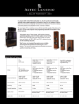
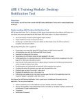
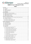
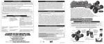
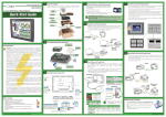
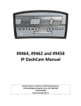
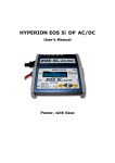
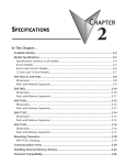
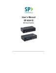
FCC ID: K6620295X20
IC :511B-20295X20
Operating Manual
Operating Manual
General Description
The VX-8R is a Dual Receive fourthband FM transceiver with extensive receive
frequency coverage, providing leading-edge features for VHF and UHF two-way amateur
communications along with unmatched monitoring capability.
The VX-8R’s small size allows you to take it anywhere - hiking, skiing, or while walking
around town, and its operating flexibility brings the user many avenues of operating
enjoyment. Besides 50, 144, (225MHz) and 430 MHz transceive operation, the VX-8R
provides receive coverage of the AM (MF) and FM broadcast bands, HF Shortwave Bands
up to 30 MHz, VHF and UHF TV bands, the VHF AM aircraft band, and a wide range of
commercial and public safety frequencies! And the optional Barometer pressure Sensor Unit
provides readout of barometric pressure and altitude while mountain climbing or hiking.
The transmitter section provides 5 Watts of clean power output on the FM operation on
the 50 MHz, 144 MHz, and 430 MHz bands with the supplied FNB-101LI Battery Pack, and
5 Watts output on 145MHz and 430 MHz, (1.5 Watts output on 225MHz) also 1.0 Watts
output on AM operation on 50 MHz. A wide variety of tone signaling formats are built into the
VX-8R, in addition to Yaesu’s exclusive ARTSTM-(Auto-Range Transponder System), which
“beeps” the user when you move out of communications range with another
ARTSTM-equipped station.
We appreciate your purchase of the VX-8R, and encourage you to read this manual
thoroughly, so as to learn about the many exciting features of your exciting new Yaesu
hand-held transceiver!
Front Panel Control & Switches
Antenna Jack
DIAL Knob
MIC/SP Jack
LED Light
PTT Switch
EAR Jack
MONI Key
EXT DC Jack
VOL Key
PWR Switch
F/W Key
Speaker
MIC
Keypad
1
Vertex Standard Co.,Ltd.
FCC ID: K6620295X20
IC :511B-20295X20
Operating Manual
Control & Connections
Antenna Jack
Connect the supplied rubber flex antenna (or another antenna
presenting a 50-Ohm impedance) here.
MIC/SP Jack
This 7-pin miniature jack connects an optional MH-74A6J Speaker
Microphone or MH-74 GPS receiver Speaker Microphone.
DIAL Knob
The main tuning Dial is used for setting the operating frequency, and is
used for audio volume level, menu selections, and other adjustments.
LED Light
This white LED glow (or flash) during “Emergency Channel” operation.
Also, this LED can be useful as a flash light in a dark environment via
the Menu Mode Item 55: LED LIGHT.
PTT Switch
Press this switch inward to transmit, and release it (to receive) after
your transmission is completed.
MONI Key
Pressing this key disables the noise squelching action, allowing you to
hear very weak signals near the background noise level.
VOL Key
Rotate the DIAL knob while pressing and holding this key to adjust the
audio volume level.
F/W Key
Pressing this key activates the “Alternate” key function of the keypad.
EAR Jack
This 3-pin miniature jack allows connection to stereo earphone.
When using after-market stereo earphones with this jack, you may
enjoy the FM broadcast band in stereo.
EXT DC Jack
This coaxial DC jack allows connection to an external DC power source
(10-16V DC). The center pin of this jack is the Positive (+) line.
PWR Switch
Press and hold this switch for 2 seconds to toggle the transceiver’s
power “on” and “off”.
Press this switch momentarily while the transceiver is turned “on” to
toggle the key lockout feature “on” or “off”.
Speaker
The internal speaker is located hear.
Keypad
These front panel’s 20 keypads select many of the most important
operating features on the VX-8R.
These functions of the keys are described in details on pages 4 and 5.
MIC
The internal microphone is located hear.
2
Vertex Standard Co.,Ltd.
FCC ID: K6620295X20
IC :511B-20295X20
Operating Manual
Keypad Function
Key
[A]
Primary Function
Secondary Function
Third Function
(Press key)
(Press + [F/W] key)
(Press & Hold key)
Switches the “Upper”
Switches the “Upper”
Activates the Dual
frequency to be the
frequency display
Receive Feature.
“Operating” (TX)
between the “Large
Band.
Character” and
“Small Character”
mode.
[B]
Switches the “Lower”
Switches the “Lower”
Activates the Dual
frequency to be the
frequency display
Receive Feature.
“Operating” (TX)
between the “Large
Band.
Character” and
“Small Character”
mode.
[UP]
Increases the VFO
Tunes the VFO
Activates the
frequency by one
frequency upward in
Scanner Upward
step or moves the
1 MHz steps.
(toward a higher
memory channel to
frequency or a higher
the next-highest
channel number).
channel.
[DOWN]
Decreases the VFO
Tunes the VFO
Activates the
frequency by one
frequency downward
Scanner Downward
step or moves the
in 1 MHz steps.
(toward a lower
memory channel to
frequency or a lower
the next-lowest
channel number).
channel.
[MENU]
Activate the APRS
No Action
Enter the Menu
(Automatic Position
Mode.
Reporting System)
function.
[BAND]
(1) Moves operation
Moves operation to
Activates the
to the next-highest
the next-lowest
Scanner Upward
frequency band.
frequency band
(toward a higher
3
Vertex Standard Co.,Ltd.
FCC ID: K6620295X20
IC :511B-20295X20
Operating Manual
(2) Activates the
frequency or a higher
Memory Bank
channel number).
feature.
[MODE]
Selects the receive
Activates the CTCSS
Engage the Special
mode among AM,
or DCS operation.
Search mode.
Reverses transmit
Switches operation to
Activates the
and receive
the “Home” (favorite
EMERGENCY
frequencies while
frequency) channel.
function.
Switches frequency
Activates the
Activates the Priority
control between the
“Memory Tune” mode
(Dual Watch)
VFO and Memory
while in the Memory
function.
System.
Recall mode.
Activates the Internet
Selects the desired
Connection feature.
transmit power
FM, and Wide FM.
[HM/RV]
working through a
repeater.
[V/M]
[Internet]
No Action.
output level.
[1]
[2]
Frequency entry digit
Selects the
Store the current
“1”.
synthesizer steps to
setting into the Direct
be used during VFO
Memory Recall
operation.
Channel “1”.
Frequency entry digit
Selects the CTCSS
Store the current
“2”.
Tone or DCS code
setting into the Direct
number.
Memory Recall
Channel “2”.
[3]
Frequency entry digit
Selects the DTMF
Store the current
“3”.
mode.
setting into the Direct
Memory Recall
Channel “3”.
[4]
Frequency entry digit
Activates the ARTS
Store the current
“4”.
feature.
setting into the Direct
Memory Recall
Channel “4”.
4
Vertex Standard Co.,Ltd.
FCC ID: K6620295X20
IC :511B-20295X20
Operating Manual
[5]
[6]
Frequency entry digit
Activates the
Store the current
“5”.
Memory Scan “Skip”
setting into the Direct
channel selection
Memory Recall
mode.
Channel “5”.
Frequency entry digit
Selects the direction
Store the current
“6”.
of the uplink
setting into the Direct
frequency shift
Memory Recall
(either “-”, “+” or
Channel “6”.
“simplex” during
repeater operation.
[7]
[8]
Frequency entry digit
Activates the AF Dual
Store the current
“7”.
function while
setting into the Direct
receiving the
Memory Recall
Broadcast Stations.
Channel “7”.
Frequency entry digit
Activates the
Store the current
“8”.
Spectrum Analyzer
setting into the Direct
TM
[9]
(Spectra-Scope )
Memory Recall
feature.
Channel “8”.
Frequency entry digit
Enters the “Special
Store the current
“9”.
Memory” mode.
setting into the Direct
Memory Recall
Channel “9”.
[0]
Frequency entry digit
Enters the Broadcast
Store the current
“0”.
Reception mode.
setting into the Direct
Memory Recall
Channel “0”.
[MONI/T-CALL]
USA Version:
Adjusts the Squelch
USA Version:
Disables the Noise
threshold level.
Disables the Noise
and Tone Squelch
and Tone Squelch
System.
System.
EXP Version:
EXP Version:
Activates the T.CALL
Activates the T.CALL
(1750 Hz) for
(1750 Hz) for
repeater access.
repeater access.
5
Vertex Standard Co.,Ltd.
FCC ID: K6620295X20
IC :511B-20295X20
Operating Manual
[VOL]
No Action
Toggle the DIAL knob
Rotate the DIAL knob
function between the
while holding this key
“Frequency Control”
to adjust the audio
and “Receiver Audio
volume level.
Control”.
[F/W]
Activates the
Disables the
Activates the
“Secondary” key
“Secondary” key
“Memory Write”
function.
function.
mode (for memory
channel storage).
Note: The [A] and [B] keys glows green when the squelch opens, and turns red during
transmission.
Accessories & Options
Accessories Supplied with the VX-8R
YHA-65 (Q3000185)
Antenna
FNB-101LI (AAG10X001)
Lithium Ion Battery Pack (7.4V/1,100mAh)
NC-86B (Q9500149)
Battery Charger
Belt Clip (RA1053600)
Operating Manual
Warranty Card
Available Options for your VX-8R
FNB-101LI
Lithium Ion Battery Pack (7.4V/1,100mAh)
FNB-102LI
Lithium Ion Battery Pack (7.4V/1,800mAh)
NC-86B/C/F/U
Battery Charger
CD-41
Rapid Charger
FBA-39
3 x “AA” Cell Battery Case (batteries not supplied)
FGPS-2
GPS Antenna
MH-74
Speaker/Microphone
BU-1
Bluetooth Adapter Unit
BH-1
Bluetooth Headset w/Stereo Earphone Jack
BH-2
Bluetooth Headset
CT-131
Microphone Adapter
CT-134
GPS Antenna Adapter
CN-3
BNC-to-SMA Adapter
E-DC-5B
DC Cable w/Noise Filter
6
Vertex Standard Co.,Ltd.
FCC ID: K6620295X20
IC :511B-20295X20
Operating Manual
E-DC-6
DC Cable; plug and wire only
CSC-98
Soft Case
Availability of accessories may vary. Some accessories are supplied as standard per local
requirements, while others may be unavailable in some regions. Consult your Yaesu Dealer
for details regarding these and any newly-available options. Connection of any
non-Yaesu-approved accessory, should it cause damage, may void the Limited Warranty on
this apparatus.
Installation of Accessories
Antenna Installation
The supplied antenna provides good results over the entire frequency range of the
transceiver. However, for enhanced base station medium-wave and shortwave reception,
you may wish to connect an external (outside) antenna.
The supplied antenna consists of two sections: the “Base Antenna” (used for operation
above 50 MHz), and the “Extender Element” (used for monitoring of frequencies below 50
MHz).
To Install the Supplied Antenna
Hold the bottom end of the antenna, then screw it onto the mating connector on the
transceiver until it is snug. Do not over-tighten by use of extreme force.
When operating the VX-8R on the 50 MHz band and lower frequencies, disconnect the
antenna cap from the base antenna, then screw the Extender Element onto the Antenna
Base. Of course, the VX-8R may be operated on frequencies higher than the 50 MHz band
while the Extender Element is still attached onto the Antenna Base.
Notes:
•
Never transmit without having an antenna connected.
•
When installing the supplied antenna, never hold the upper part of the antenna while
screwing it onto the mating connector on the transceiver.
•
If using an external antenna for transmission, ensure that the SWR presented to the
transceiver is 1.5:1 or lower.
•
Take care not lose the antenna cap when removing it from the Base Antenna.
Installation of FNB-101LI Battery Pack
The FNB-101LI is a high-performance Lithium-Ion battery providing high capacity in a very
compact package. Under normal use, the FNB-101LI may be used for approximately 300
charge cycles, after which operating time may be expected to decrease. If you have an old
7
Vertex Standard Co.,Ltd.
FCC ID: K6620295X20
IC :511B-20295X20
Operating Manual
battery pack which is displaying capacity which has become diminished, you should replace
the pack with a new one.
1.
Install the FNB-101LI as shown in the illustration.
2.
Close the Battery Pack Latch on the bottom of the radio.
If the battery has never been used, or its charge is depleted, it may be charged by
connecting the NC-86B/C Battery Charger, as shown in the illustration, to the EXT DC jack.
If only 12 ~ 16 Volt DC power is available, the optional
E-DC-5B or E-DC-6 DC Adapter (with its cigarette lighter plug) may also be used for
charging the battery, as shown in the illustration.
While the battery is being charged, the display will indicate “CHARGING” and the
key will
glow red. The S-meter will deflect according to the charging status. When charging is
finished, the display will change to indicate “COMPLETE” and the
key will glow green.
Installation of FBA-39 Alkaline Battery Case (Option)
The optional FBA-39 Battery Case allows receive monitoring using three “AA” size Alkaline
batteries. Alkaline batteries can also be used for transmission in an emergency, but power
output will only be selectable 1 W and 50 mW.
To Install Alkaline Batteries into the FBA-39
1.
Slide the batteries into the FBA-39 as shown in the illustration, with the Negative [–]
side of the batteries touching the spring connections inside the FBA-39.
2.
Open the Battery Pack Latch on the bottom of the radio.
3.
Install the FBA-39 as shown in the illustration, with the [+] side facing the bottom of the
transceiver.
4.
Close the Battery Pack Latch on the bottom of the radio.
The FBA-39 does not provide connections for charging, since Alkaline cells cannot be
re-charged. Therefore, the NC-86B/C, E-DC-5B, or E-DC-6 may safely be connected to the
EXT DC jack when the FBA-39 is installed.
Notes:
•
The FBA-39 is designed for use only with AA-type Alkaline cells.
•
If you do not use the VX-8R for a long time, remove the Alkaline batteries from the
FBA-39, as battery leakage could cause damage to the FBA-39 and/or the transceiver.
Battery Life Information
When the battery charge is almost depleted, a “Low Voltage” indicator will appear on the
display. When this icon appears, it is recommended that you charge the battery soon.
8
Vertex Standard Co.,Ltd.
FCC ID: K6620295X20
IC :511B-20295X20
Operating Manual
(1) TX 6 sec., RX 6 sec. and Squelched 48 sec.
(2) Continuous signal reception
The current battery voltage can be displayed manually on the LCD, by following the
instructions on page ??.
Battery capacity may be reduced during extremely cold weather operation. Keeping the
radio inside your parka may help preserve the full charge capacity.
AC Operation Using NC-86B/C (Receiving only)
The VX-8R may be operated from your house current by use of the supplied NC-86B/C
Battery Charger. The NC-86B/C should only be used for reception, because it is not capable
of supplying sufficient current to support transmission.
To use the NC-86B/C, turn the transceiver off, then plug the miniature connector of the
Battery Charger into the EXT DC jack on the side of the radio. Now plug the Battery Charger
into the wall outlet. You may now turn on the transceiver.
Interface of Packet TNC
The VX-8R may be used for Packet operation, using the optional CT-131 microphone
adapter (availablefrom your Yaesu dealer) for easy interconnection to commonly-available
connectors wired to your TNC. You may also build your own cable using a four-conductor
miniature phone plug, per the diagram below.
The audio level from the receiver to the TNC may be adjusted by using the VOLUME knob,
as with voice operation. The input level to the VX-8R from the TNC should be adjusted at the
TNC side; the optimum input voltage is approximately 5 mV at 2000 Ohms.
Be sure to turn the transceiver and TNC off before connecting the cables, so as to prevent
voltage spikes from possibly damaging your transceiver.
Operation
Note: Hi! I’m R. F. Radio, and I’ll be helping you along as you learn the many features of the
VX-8R. I know you’re anxious to get on the air, but I encourage you to read the “Operation”
section of this manual as thoroughly as possible, so you’ll get the most out of this fantastic
new transceiver. Now, let’s get operating!
Switching Power On and Off
1.
Be sure the battery pack is installed, and that the battery is fully charged. Connect the
9
Vertex Standard Co.,Ltd.
FCC ID: K6620295X20
IC :511B-20295X20
Operating Manual
antenna to the top panel ANTENNA jack.
2.
Press and hold in the [PWR] switch (on the right side of the front panel) for 2 seconds.
Two beeps will be heard when the switch has been held long enough, and the opening
message will appear on the display, then frequency display will appear. After another
two seconds, the receive-mode Battery Saver function will become active, unless you
have disabled it (see page ??).
3.
To turn the VX-8R off, press and hold in the [PWR] switch again for 2 seconds.
Note: If you don’t hear the two “Beep” tones when the radio comes on, the Beeper may have
been disabled via the Menu system. See page ??, which tells you how to reactivate the
Beeper.
Adjusting the Volume Level
Rotate the DIAL knob while pressing and holding the [VOL] key to set the desired audio level.
Clockwise rotation increases the volume level.
The Volume level may be set on the “Main” and “Sub” bands separately.
Squelch Adjustment
The VX-8R’s Squelch system allows you to mute the background noise when no signal is
being received. Not only does the Squelch system make “standby” operation more pleasant,
it also significantly reduces battery current consumption.
The Squelch system may be adjusted independently for the FM and Wide-FM (FM
Broadcast) modes.
1.
Press the [F/W] key, then press the [MONI/T-CALL] key on the left side of the radio.
This provides a “Short-cut” to Menu Item 96: SQL LEVEL.
2.
Now, rotate the DIAL knob to set the background noise is just silenced (typically at a
setting of about “3” or “4” on the scale); this is point of maximum sensitivity to weak
signals.
3.
When you are satisfied with the Squelch threshold setting, press the PTT key
momentarily to save the new setting and exit to normal operation.
4.
You may also adjust the Squelch setting by using the “Set” (Menu) mode. See page ??
for details.
Note 1: The Squelch level may be set on the “Main” and “Sub” bands separately.
Note 2: If you’re operating in an area of high RF pollution, you may need to consider “Tone
Squelch” operation using the built-in CTCSS Decoder. This feature will keep your radio quiet
until a call is received from a station sending a carrier which contains a matching
10
Vertex Standard Co.,Ltd.
FCC ID: K6620295X20
IC :511B-20295X20
Operating Manual
(subaudible) CTCSS tone. Or if your friends have radios equipped with DCS (Digital Coded
Squelch) like your VX-8R has, try using that mode for silent monitoring of busy channels.
Selecting the Operating Band
In the factory default configuration, the VX-8R operates in the “Dual Receive” mode.
During Dual Receive operation, the “VFO-A” frequency will be displayed on the upper side
of the LCD, and the “VFO-B” frequency will be displayed on the lower side, with the
“Operating” band (the band on which transmission and band/frequency change are
possible) being indicated in large characters, and “Receive only” band being indicated in
small characters.
To switch the “Operating” band: press the [A] key momentarily to engage the “VFO-A”
frequency as the “Operating” band. Alternatively, press the [B] key momentarily to engage
the “Sub” band frequency as the “Operating” band, described previously.
Press and hold in the [A] or [B] key for 1/2 seconds to switch to Mono Band Operation with a
double-size display.
During Mono band operation, you may press the [F/W] key, then press the [A]/[B] key, to
change the display to show only large characters.
Selecting the Frequency Band
The VX-8R covers an incredibly wide frequency range, over which a number of different
operating modes are used. Therefore, the VX-8R’s frequency coverage has been divided
into different operating bands, each of which has its own pre-set channel steps and
operating modes. You can change the channel steps and operating modes later, if you like
(see page ??).
To Change Operating Bands
1.
Press the [BAND] key repetitively. You will see the LCD indication move toward a higher
frequency band each time you press the [BAND] key. Indicates a Band Number
according to the receiving frequency on the display.
2.
If you wish to move the operating band selection downward (toward lower frequencies),
press the [F/W] key first, then press the [BAND] key.
3.
The VX-8R uses a dual VFO system (described previously). To switch TX/RX operation
from the “VFO-A” to the “VFO-B” instantly, press the [B] key momentarily. Pressing the
[A] key will return the VX-8R to the “VFO-A”. The frequency band bearing the “Large”
characters is the band on which transmission is possible; the band designated by
11
Vertex Standard Co.,Ltd.
FCC ID: K6620295X20
IC :511B-20295X20
Operating Manual
“Small” characters may only be used for reception.
4.
Once you have selected the desired band, you may initiate manual tuning (or scanning)
per the discussions on the next page.
Note 1: The SW Band and Information Band reception is only possible on the “VFO-A”.
Note 2: The VX-8R has an AM/FM Broadband radio. You can receive these bands
independently. See page ?? for details.
Note 3: If desired, you may omit (skip) one or more bands from the band selection loop for
faster recall of your favorite operating bands. See page ?? for details.
Frequency Navigation
The VX-8R will initially be operating in the “VFO” mode, as just described. This is a
channelized system which allows free tuning throughout the currently-selected operating
band.
Three basic frequency navigation methods are available on the VX-8R:
1) Tuning Dial
Rotation of the DIAL knob allows tuning in the pre-programmed steps established for the
current operating band. Clockwise rotation of the DIAL knob causes the VX-8R to be tuned
toward a higher frequency, while counter-clockwise rotation will lower the operating
frequency.
If you press the [F/W] key momentarily, then rotate the DIAL knob, frequency steps of 1 MHz
will be selected. This feature is extremely useful for making rapid frequency excursions over
the wide tuning range of the VX-8R.
2) Direct Keypad Frequency Entry
The desired operating frequency may be entered directly from the keypad.
The operating mode will automatically be set once the new frequency is entered via the
keypad.
To enter a frequency from the keypad, just press the numbered digits on the keypad in the
proper sequence. There is no “Decimal point” key on the VX-8R, so if the frequency is below
100 MHz (e.g. 15.150 MHz), any required leading zeroes must be entered. However, there
is a short-cut for frequencies ending in zero - press the [V/M] key after the last non-zero
digit.
Examples:
To enter 146.520 MHz, press [1] Æ [4] Æ [6] Æ [5] Æ [2] Æ [0]
To enter 15.255 MHz, press [0] Æ [1] Æ [5] Æ [2] Æ [5] Æ [5]
To enter 1.250 MHz (1250 kHz), press [0] Æ [0] Æ [1] Æ [2] Æ [5] Æ [0]
To enter 0.950 MHz (950 kHz), press [0] Æ [0] Æ [0] Æ [9] Æ [5] Æ [0]
To enter 430.000MHz, press [4] Æ [3] Æ [V/M]
12
Vertex Standard Co.,Ltd.
FCC ID: K6620295X20
IC :511B-20295X20
Operating Manual
3) Scanning
From the VFO mode, press and hold in either the [UP] or [DOWN] key for one second to
initiate upward or downward scanning, respectively, and will stop when it receives a signal
strong enough to break through the Squelch threshold. The VX-8R will then hold on that
frequency according to the setting of the “RESUME” mode (Menu Item 89: SCAN RESUME).
See page ?? for details.
If you wish to reverse the direction of the scan (i.e. toward a lower frequency, instead of a
higher frequency), just rotate the DIAL knob one click in the counter-clockwise direction
while the VX-8R is scanning. The scanning direction will be reversed. To revert to scanning
toward a higher frequency once more, rotate the DIAL knob one click clockwise.
Press the PTT switch momentarily to cancel the scanning.
Transmission
Once you have set up an appropriate frequency inside one of the three (or four) Amateur
bands on which the VX-8R can transmit (50 MHz, 144 MHz, or 430 MHz, plus 222 MHz on
the USA version), you’re ready to transmit. These are the most basic steps; more advanced
aspects of transmitter operation will be discussed later.
1.
To transmit, press the PTT switch, and speak into the front panel microphone (located in
the upper right-hand corner of the speaker grille) in a normal voice level. The LED of the
[A] or [B] which is designated the “Main” band will glow red during transmission.
2.
To return to the receive mode, release the PTT switch.
3.
During transmission, the relative power level will be indicated on the LCD. Additionally,
the “L1”, “L2”, “L3”, or “HI” icon will appear at the left side of the PO meter,
corresponding with the “Power” Level setting.
Note 1: If you’re just talking to friends in the immediate area, you’ll get much longer battery
life by switching to Low Power operation. To do this, press the [F/W] key, then press the
[Internet] key so that the “Low Power” icon appears at the bottom of the display. And don’t
forget: always have an antenna connected when you transmit.
Note 2 Transmission is not possible on “Sub” band and any operating bands other than the
50 MHz, 144 MHz, 222 MHz (USA version), and 430 MHz bands on the “Main” band.
Changing the Transmitter Power Level
You can select between a total of four transmitter power levels on your VX-8R. The exact
power output will vary somewhat, depending on the voltage supplied to the transceiver. With
the standard FNB-101LI Battery Pack and external DC source, the power output levels
available are:
13
Vertex Standard Co.,Ltd.
FCC ID: K6620295X20
IC :511B-20295X20
Operating Manual
To change the power level:
1.
The default setting for the power output is “High;” in this configuration, the display
shows “HI” icon. Pressing the [F/W] key, followed by the [Internet] key, causes the
power level “L1”, “L2”, or “L3” to appear.
2.
Press the [F/W] key, followed by the [Internet] key (repeatedly, if necessary) to make the
“HI” icon appear and restore “High Power” operation.
Note 1: The VX-8R is smart! You can set up Low power on one band (like UHF), while
leaving VHF on High power, and the radio will remember the different settings on each band.
And when you store memories, you can store High and Low power settings separately in
each memory, so you don’t waste battery power when using very close-in repeaters!
Note 2: When you are operating on one of the Low power settings, you can press the
key,
then press the PTT switch, to cause the VX-8R to transmit (temporarily) on High power. After
one transmission, the power level will revert to the previously-selected Low power setting.
AM and FM Broadcast Reception
The VX-8R includes provision for reception of AM and FM broadcasts. FM broadcast
reception, utilizes a wide-bandwidth filter and stereo decoder which provides excellent
fidelity.
1.
Press the [A] key momentarily to engage the “VFO-A” as the “Operating” band.
2.
Press the [F/W] key, then press the [0(RADIO)] key to enter the Broadcast Reception
mode.
3.
Press the [BAND(SC-M BND DW)] key to toggle the receiving band between “AM
broadcast” and “FM broadcast”.
The AM broadcast coverage is 510 to 1790 kHz and utilizes AM mode. The Band
Number changes to “A” (which means AM) and an Operating Mode icon changes to
“AM”.
The FM broadcast coverage is 76.00 to 107.90 MHz and utilizes Wide-FM mode. The
Band Number changes to “F” (which means FM) and an Operating Mode icon changes
to “WFM”.
4.
Rotate the DIAL knob to select the desired station.
5.
To exit to normal operation, press the [F/W] key followed by the [0(RADIO)] key.
Note: The AM and FM Broadcast reception is only possible on the “VFO-A”.
Antenna Selection
The VX-8R allows you to select the antenna for the Broadcast Reception.
1.
Press and hold the [MENU] key for one second to enter the Menu mode.
14
Vertex Standard Co.,Ltd.
FCC ID: K6620295X20
IC :511B-20295X20
Operating Manual
2.
Rotate the DIAL knob to select Menu Item 4: ANTENNA AM (for the AM Antenna
selection) or 6: ANTENNA FM (for the FM Antenna selection).
3.
Press the [MENU] key momentarily to enable the antenna selection.
4.
Rotate the DIAL knob to select the antenna to be used.
AM Antenna selection: “BAR ANTENNA” (Uses the internal Bar Antenna) or “BAR &
EXT” (Uses both the internal Bar Antenna and the Rubber Flex Antenna).
FM Antenna selection: “EXT ANTENNA” (Uses the Rubber Flex Antenna) or “EAR
PHONE” (Uses the Earphone Antenna).
5.
When you finish the selection, press the PTT switch to exit from the Menu mode and
return to the Broadcast Reception mode.
If you wish to output the audio of the FM Broadcast station to the VX-8R internal speaker
while using the earphone antenna, select Menu Item 95: SPEAKER OUT to “SPEAKER”.
AF Dual Function
The AF Dual Function allows you to monitor your desired amateur band frequency while
receiving AM or FM broadcast stations. Furthermore, you may transmit on the amateur
frequency by pressing the PTT switch.
When a signal is received in the amateur band, the audio is output instead of the AM or FM
Broadcast station. When the amateur band signal drops, the SUB-RX Operation is resumed
as determined by the user settings in the below procedures. If you activates the AF Dual
Function while Dual receiving, you may operate the Triple Watch functions (two amateur
frequencies plus one broadcast station)!
1.
Set the VX-8R to the desired amateur band frequency by the VFO or Memory channel
selection.
2.
Press the [F/W] key, then press the [7(AF DUAL)] key. This provides a “Short-cut” to
Menu Item 1: AF DUAL.
3.
Rotate the DIAL knob to select the resume mode of the AF Dual function. Available
selections are:
TX 1S - TX 10S: Sets the period of time after you transmit an amateur signal before the
AM or FM Broadcast station will be heard from the speaker, and the AF Dual function is
resumed.
However, if a signal is received in the amateur band, the AF Dual function will halt on
the amateur band frequency and the AF Dual function does not resume.
TRX 1S - TXR 10S: When the selected time passes after the amateur band signal
drops or transmission is over, the AM or FM Broadcast station will be heard from the
speaker and the AF Dual function is resumed.
15
Vertex Standard Co.,Ltd.
FCC ID: K6620295X20
IC :511B-20295X20
Operating Manual
HOLD: When a signal is received in the amateur band or if you transmit on the amateur
band, the AF Dual function will halt on the amateur band frequency (the AF Dual
function does not resume.). You must manually re-initiate the AF Dual function, if you
wish to resume.
OFF: Disable the AF Dual function.
4.
Press the PTT switch to exit from the resume mode selection mode of the AF Dual
function.
5.
Press the [F/W] key, then press the [0(RADIO)] key to enter the Broadcast Reception
mode.
6.
Press the [BAND(SC-M BND DW)] key to toggle the receiving band between “AM
broadcast” and “FM broadcast”.
7.
Rotate the DIAL knob to select the desired Broadcast station.
8.
When a signal is received in the amateur band, the amateur band audio is output to the
speaker. The AM or FM Broadcast station will no longer be heard. When the amateur
band signal drops, the AM or FM Broadcast station will be heard from the speaker, and
the AF Dual function is resumed (the amateur band frequency is monitored while the
AM broadcast station is heard from the speaker) according to the AF Dual function
Resume mode selected in step 3 above.
9.
You may monitor the amateur band forcibly by holding the [MONI/T-CALL] switch.
To disable the AF Dual function, just repeat the above procedure, rotating the DIAL knob to
select “OFF” in step 3 above.
Note 1: You may transmit with the VX-8R on the frequency set in step1 above by pressing
the PTT switch, even if the AF Dual function is activated.
Note 2: You may change the frequency of the amateur band by rotating the DIAL knob while
pressing the [MONI/T-CALL] switch.
Note 3: When the [V/M] key is pressed, the VX-8R recalls AM and FM Broadcast station
only.
16
Vertex Standard Co.,Ltd.
FCC ID: K6620295X20
IC :511B-20295X20
Operating Manual
This equipment has been tested and found to comply with the limits for a Class B digital
device, pursuant to Part 15 of the FCC Rules. These limits are designed to provide
reasonable protection against harmful interference in a residential installation. This
equipment generates, uses and can radiate radio frequency energy and, if not installed
and used in accordance with the instructions, may cause harmful interference to radio
communications. However, there is no guarantee that interference will not occur in a
particular installation.
If this equipment does cause harmful interference to radio or television reception, which
can be determined by turning the equipment off and on, the user is encouraged to try to
correct the interference by one or more of the following measures:
-- Reorient or relocate the receiving antenna.
-- Increase the separation between the equipment and receiver.
-- Connect the equipment into an outlet on a circuit different from that to which the
receiver is connected.
-- Consult the dealer or an experienced radio/TV technician for help.
This device complies with Part 15 of the FCC Rules. Operation is subject to the
following two conditions: (1) this device may not cause harmful interference, and (2) this
device must accept any interference received, including interference that may cause
undesired operation.
Part 15.21: Changes or modifications to this device not expressly approved by Vertex
Standard could void the user’s authorization to operate this device.
DECLARATION BY MANUFACTURER
The scanner receiver is not a digital scanner and is incapable of being converted or
modified to a digital scanner receiver by any user.
17
Vertex Standard Co.,Ltd.