1
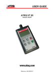
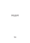
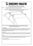
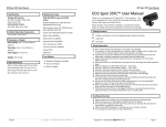
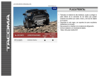
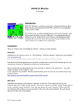
TOYOTA RAV4 2013 - CROSSBAR KIT Preparation Part Number: PT278-42130 Recommended Sequence of Application Kit Contents Item # 1 2 3 Quantity Reqd. 1 1 1 Description Crossbar Assembly Front (long) Crossbar Assembly Rear (short) User’s Manual Item # 1 2 3 Accessory *Mandatory Hardware Bag Contents Item # 1 2 3 4 5 6 7 Quantity Reqd. 1 1 1 1 1 4 2 Description Front LH Side Lower Clamp Front RH Side Lower Clamp Rear LH Side Lower Clamp Rear RH Side Lower Clamp Lever Key Lever Assembly with t-bolt Forward Limit Label Additional Items Required For Installation Item # 1 2 3 Quantity Reqd. Description Conflicts Recommended Tools Personal & Vehicle Protection Notes Safety Glasses Safety Gloves Vehicle Protection Wrist & Belt Buckle Protection Cloth Special Tools Notes Installation Tools Notes Vehicle Service Parts (may be required for reassembly) Item # 1 2 3 Notes Cleaner Approved Cleaner STOP: Damage to the vehicle may occur. Do not proceed until process has been complied with. OPERATOR SAFETY: Use caution to avoid risk of injury. CAUTION: A process that must be carefully observed in order to reduce the risk of damage to the accessory/vehicle and to ensure a quality installation. TOOLS & EQUIPMENT: Used in Figures calls out the specific tools and equipment recommended for this process. REVISION MARK: This mark highlights a change in installation with respect to previous issue. SAFETY TORQUE: This mark indicates that torque is related to safety. General Applicability Issue: C 1/25/2013 Description Legend Tape Measure (Metric) Non-Intrusive Infrared Temp Probe/Gun Heat Gun Special Chemicals Quantity Reqd. Page 1 of 4 pages TOYOTA RAV4 2013 - CROSSBAR KIT Procedure Care must be taken when installing this accessory to ensure damage does not occur to the vehicle. The installation of this accessory should follow approved guidelines to ensure a quality installation. These guidelines can be found in the "Accessory Installation Practices" document. This document covers such items as: Vehicle Protection (use of covers and blankets, cleaning chemicals, etc.). Safety (eye protection, rechecking torque procedure, etc.). Vehicle Disassembly/Reassembly (panel removal, part storage, etc.). Electrical Component Disassembly/Reassembly (battery disconnection, connector removal, etc.). Please see your Toyota dealer for a copy of this document. Fig. 1-1 83mm (3.25in.) 1. Affix front crossbar “Forward Limit” warning labels to side rails. Front of Vehicle (a) The side rail surface temperature must be between 60˚F and 110˚F. (a) Clean the area on the front LH side rail. (b) Using a ruler, measure 83mm (3.25 in.) back from front of side rail. (c) Remove adhesive backing from label and position so that the triangle on the label is pointing to the rear of the vehicle. Label should be 83mm back from back of the front rail cover. (Fig. 1-1) Fig. 2-1 Front of Vehicle (d) Repeat for RH side rail. 2. Install Crossbars (Fig. 2-1) (a) Make sure FORWARD arrows on crossbar end supports are pointing toward the front of the vehicle. (Fig. 2-1) (b) Load front crossbar (longer) so that the front of the crossbar touches the line on “forward limit” warning label. (2 places) (Fig. 2-1) ~50mm (~2 in.) (c) Load rear crossbar (shorter) so that the rear of the crossbar is ~50mm (~2 in.) from the front of the rear rail cover. (2 places) (Fig. 2-1) NOTE: DO NOT POSITION FRONT CROSSBAR ON OR FORWARD OF WARNING LABEL. Front of Vehicle (d) If necessary, adjust the width of the crossbar by sliding the R.H. end support so that there is a secure fit on the side rail. (Fig. 2-2c) Fig. 2-2 Issue: C 1/25/2013 Page 2 of 4 pages TOYOTA RAV4 2013 - CROSSBAR KIT Procedure Fig. 3-1 3. Install Lower Clamps Tighten (a) Verify proper clamps prior to installation by looking for position markings on top of clamp. (4 places) (Fig. 3-1) Front of Vehicle Position Marking (b) Carefully position clamp underneath side rail under cross bar support. Use vehicle protection to avoid contact with surface. While positioning the clamp, insert the lever through the hole on the support and into the clamp. Make sure lever screw engages and bottom support is flush with upper support. Tighten lever handle until handle bottoms out on support. (4 places) (Fig. 3-1) (c) After lever is tight, back off one turn, line the lever up with the opening in the support and close lever. (4 places) (Fig. 3-2) Fig. 3-2 Be careful to avoid pinching. NOTE: ENSURE THE CROSSBAR IS SECURELY FASTENED TO THE SIDE RAILS. (d) Using the supplied key, turn lock in lever to lock the crossbar in position. (4 places) (Fig. 3-3) Fig. 3-3 UNLOCKED 4. Install User’s Manual (a) Place Crossbar User’s Manual and lever key in the vehicle’s glove box. LOCKED Issue: C 1/25/2013 Page 3 of 4 pages TOYOTA RAV4 2013 - CROSSBAR KIT Checklist - these points MUST be checked to ensure a quality installation. Check: Look For: Accessory Function Checks Ensure crossbars are secure and in correct Front crossbar should not be forward of position warning label. Crossbar User’s Manual/ Lever Key User’s Manual, Installation Instructions and Lever Key inside vehicle glove box. Ensure crossbars are fully clamped with no Crossbar Gaps gaps around the end supports. Ensure the crossbars FORWARD arrow is Crossbar Orientation facing the front of the vehicle. Vehicle Function Checks Vehicle Appearance Check After accessory installation and removal of protective cover(s), perform a visual inspection. Issue: C 1/25/2013 Page 4 of 4 pages Ensure no damage (including scuffs and scratches) was caused during the installation process. (For PPO installations, refer to TMS Accessory Quality Shipping Standard.)