1
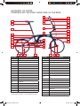
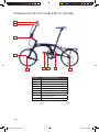
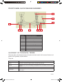
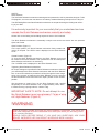
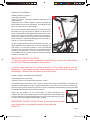
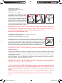
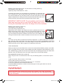
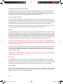
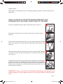
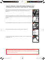
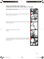
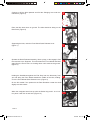
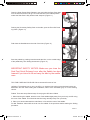
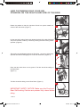
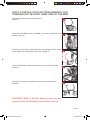
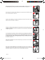
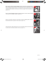
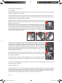
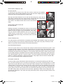
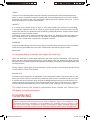
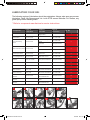
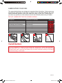
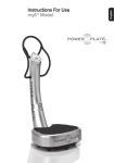
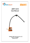
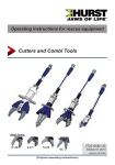
OWNERS MANUAL
Untitled-1 1
25/9/08 09:31:57
CONTENTS
PAGE 3
PAGE 3-4
PAGE 4
PAGE 4
PAGE 4
PAGE 5
PAGE 6
PAGE 7
PAGE 7
PAGE 8
PAGE 9
PAGE 9
PAGE 9
PAGE 10
PAGE 10
PAGE 11
PAGE 11
PAGE 11
PAGE 11
PAGE 12-13
PAGE 12
PAGE 12
PAGE 12
PAGE 12
PAGE 12
PAGE 13
PAGE 13-14
PAGE 15-17
PAGE 17
PAGE 18
PAGE 19
PAGE 20
PAGE 20-21
PAGE 21
PAGE 21-23
PAGE 21-23
PAGE 24
PAGE 24
PAGE 25
PAGE 25
PAGE 25
INTRODUCTION:
DISCLAIMER:
GETTING TO KNOW YOUR ORi:
BEFORE RIDING YOUR ORi:
MAXIMUM WEIGHT LIMIT:
GLOSSARY OF PARTS: Right hand side of the bike
GLOSSARY OF PARTS: Left hand side of the bike
FRONT WHEEL QUICK RELEASE ASSEMBLY:
GLOSSARY OF TECHNICAL TERMS:
SAFETY:
AREAS OF ADJUSTMENT:
SADDLE HEIGHT:
SADDLE FRONT AND BACK ADJUSTMENT:
HANDLEBAR HEIGHT:
HANDLEBAR ROTATION:
BRAKE LEVER POSITION:
BRAKE LEVER ‘REACH’:
TYRE PRESSURES:
RECOMMENDED SPARES FOR YOUR ORi:
FOLDING AND UNFOLDING YOUR ORi:
SELF-LOCKING CATCHES:
DROPOUT CATCH:
BRAKES:
SEAT POST:
FASTENERS:
FINGER TRAPS:
HOW TO UNFOLD YOUR ORi FROM STORAGE FOLD:
HOW TO STORAGE FOLD YOUR ORi:
TIPS FOR CARRYING YOUR ORi:
HOW TO PARKING FOLD YOUR ORi:
HOW TO UNFOLD YOUR ORi FROM PARKING FOLD:
ORi PRE-RIDE CHECK:
CHECK-LIST:
RIDING YOUR ORi:
HOW TO REMOVE FRONT AND REAR WHEELS IN THE EVENT OF PUNCTURES:
FRONT WHEEL REMOVAL:
REAR WHEEL REMOVAL: C8 Model
CHAIN TENSION: C8 Model
REAR WHEEL REMOVAL: M9 Model
REAR WHEEL REFITTING: M9 Model
CHAIN TENSION: M9 Model
PAGE 25
PAGE 25
PAGE 26
PAGE 26
PAGE 26
PAGE 27
PAGE 27
PAGE 27
PAGE 27
PAGE 27
ROUTINE MAINTENANCE:
CLEANING YOUR ORi:
SHIMANO PARTS:
DRIVE TRAIN:
BRAKE ADJUSTMENT:
TYRES:
WHEELS:
STEERING:
SEAT POST:
SOCKAL CLIP:
PAGE 28
PAGE 28
PAGE 29
LUBRICATING YOUR ORi:
LUBRICATE THE FOLLOWING AREAS:
DO NOT LUBRICATE THE FOLLOWING AREAS:
PAGE 2
ORi Manual revised.indd 2
28/3/08 09:41:06
INTRODUCTION:
Congratulations, and thank you for choosing ORi.
Your ORi has been designed and produced to make the most of the fantastic benefits that our
advanced and unique design offers, and to provide you with the best possible performance for many
years to come. To get the best from your new bike, and for your own safety, it is very important that
you fully understand the operation of the ORi folding bike before riding.
This owner’s manual assumes a working knowledge of bicycles and an understanding that the regu
lar inspections and maintenance which are outlined are essential to ensure the safe performance and
longevity of your bike. If you are not experienced in owning and riding a bicycle, always consult your
ORi dealer about important issues. This is especially important with any folding bike.
Please read, understand and digest all the sections that apply to your bike before riding your bike
for the first time.
The ORi has passed the arduous DIN testing standard. This means ORi has been
tested for its intended use of general road riding. Do not ride your ORi on rough offroad terrain. Incorrect use can lead to serious injury.
DISCLAIMER:
By opening the packaging; or by assembling the bike; or by using the bike (or by allowing it to be
unpacked, assembled or used) you are agreeing to: (a) accept and be bound by the terms set out
below; and (b) require anyone using the bike to be bound by such terms. If you are unwilling to be
bound by these terms you may return the bike unused for a full refund.
Terms:
You agree that you will:
read the manual carefully and follow its instructions and guidance before assembling
(a)
or using the bike;
(b)
view the demonstration of the correct folding / unfolding procedures on the DVD provided (or view this on our website or ask a dealer for a personal demonstration);
(c)
carry out the pre-ride checks, described in the manual, on each occasion before riding
the bike;
(d)
always make sure any other users of the bike carefully read the manual, view the
demonstration, follow the instructions and guidance given, and carry out the pre-ride
checks before they assemble, use or ride the bike.
(e)
assume all the risks resulting from or arising out of incorrect assembly or use of the bike
or failure to carry out properly the pre-ride checks;
(f)
waive any claims you may have against ATB Sales Limited resulting from the incorrect
assembly or use of the bike or your failure to carry out properly the pre-ride checks;
(g)
indemnif y AT B Sales Limit ed and hold it harmless against all claims by ot her users
of the bike, whom, through a failure on your part, have not read the manual carefully
and viewed the demonstrations, and / or whom you have permitted to incorrectly assemble or use the bike, and / or whom you have permitted to ride the bike without carrying out properly the pre-ride checks.
(h)
And you also agree that ATB Sales Limited will not be liable for any defect in the bike
arising from fair wear or tear, wilful damage, negligence, abnormal use, a failure to follow the guidance given, misuse or alteration or repair (other than a repair carried out
by an authorised dealer);
PAGE 3
ORi Manual revised.indd 3
28/3/08 09:41:06
Please Note:
(1)
A copy of the manual with instructions for folding and unfolding the bike together with
details of necessary pre-ride checks and other guidance for maintenance is contained
within the packaging
(2)
A DVD demonstrating the correct ways to fold and unfold the bike is also contained
in the packaging.
(3)
A demonst rat ion of t he correct way t o f old and unf old t he bike is also available f or
viewing on our website; www.oribikes.com
(4)
Our aut horised dealers will also demonst rat e t he f olding and unf olding procedures
to you, a list of our authorised dealers is on our website.
The bike will be safe if it is assembled and used in accordance with the instructions and guidance. However, incorrect assembly, incorrect unfolding or incorrect use may result in serious injury
or death.
Your statutory rights are not affected by these Terms and they do not exclude or limit ATB Sales
Limited’s liability for personal injury or death caused by its negligence.
GETTING TO KNOW YOUR ORi:
BEFORE RIDING YOUR ORi:
The ORi is folded and unfolded in a series of individual steps. It is important that these steps are
made in the correct sequence, to ensure the most efficient and safe folding and un-folding. Please
take some time to refer to the ORi Folding Bike Folding Sequences on pages 13-19.
If you received your ORi in its shipping box it is important to undertake a comprehensive check
of your bike to satisfy yourself that the bike is in a safe condition to ride. Please refer carefully to all
the sections below.
Remove all extraneous packaging and protective material from the bike. You will need to unfold the
bike and perhaps make some adjustments to accommodate your requirements, please refer to areas
of adjustment starting on Page 9.
MAXIMUM WEIGHT LIMIT:
The maximum combined weight of rider and luggage should not
exceed 110kg.
PAGE 4
ORi Manual revised.indd 4
28/3/08 09:41:06
GLOSSARY OF PARTS:
STANDING ON THE RIGHT-HAND SIDE OF THE BIKE
2
5
39
3
38
7
1a
4a
6
8
10
9
37
12
21
36
35
33
13
14
15
24
34
16
23a
22a
26
28
32
40
30 31a
29
25
19
18 17b
Number
Component Description
Number
Component Description
1a
Right-Hand Handlebar Grip
21
Mainframe
2
Handlebars
22a
Right-Hand Pedal
3
Upper Stem Clamp
23a
Right-Hand Crank Arm
4a
Right-Hand Brake Lever
24
Chain Set
5
Gear Shifter
25
Chain
6
Upper Handlebar Stem
26
Swinging Arm
7
Upper Handlebar Stem Clamp
28
Sockal Clip
8
Upper Hinge Parts
29
Tensioner (C8) / Rear Derailleur (M9)
9
Front Self-locking Catch
30
Rear Wheel
10
Lower Hinge Parts
12
Lower Stem
31a
Wheel Nut (C8) / Quick Release Nut
(M9)
13
Headset
32
Sprocket (C8) / 9spd Cassette (M9)
14
Lockstop
33
Rear Rack
15
Front Brake Calliper
34
Rear Brake Calliper
16
Front Wheel
35
Rear Self-locking Catch
Front Wheel Quick Release Nut *
36
Seat Clamp Quick Release Lever
Front Forks
37
Seat Post
Front Mudguard
38
Saddle Clamp Bolt
39
Saddle
40
Replaceable Rear Mech Hanger
17b
18
19
* Comprised of Number 7 & 8 as detailed on Page 7
PAGE 5
ORi Manual revised.indd 5
28/3/08 09:41:07
STANDING ON THE LEFT-HAND SIDE OF THE BIKE
1b
4b
11
20
22b
17a
23b
27
Number
Component Description
1b
Left-Hand Handlebar Grip
4b
Left-Hand Brake Lever
11
Secondary Safety Clip (Optional)
17a
Front Wheel Quick Release Lever
20
Dropout Montaque
22b
Left-Hand Pedal
23b
Left-Hand Crank Arm
27
Swinging Arm Pivot
31b
Quick Release Lever
31b
PAGE 6
ORi Manual revised.indd 6
28/3/08 09:41:07
FRONT WHEEL QUICK RELEASE ASSEMBLY
1
4
9
7
6
3
5
2
10
Number
Component Description
1
Front Mudguard Assembly
2
Right-Hand Fork Dropout
3
Left-Hand Fork Dropout
4
Quick Release Lever (shown closed)
5
Quick Release Shaft
6
Quick Release Adjusting Nut
7
Quick Release Lock Nut
8
Quick Release Lever Cam
9
Quick Release Spring
10
Quick Release Bobbin
8
GLOSSARY OF TECHNICAL TERMS:
There are also a few technical terms for parts and tools used in this manual that are not
shown in the glossary of parts above.
They are:
Dropout
The dropouts are the parts of the frame and front fork that the wheels slot into.
Socket Head Cap
Screw
Also known as an Allen Bolt, this is a bolt with a hexagonal cut out in its head. An
Allen Key is required to tighten /loosen. Used all over your ORi.
Torque
A twisting force, in this case relating to the tightness of a nut and bolt, screw or quick
release.
Torque Wrench
A tool for setting and adjusting the tightness of nuts and bolts to a desired value.
Sockal Clip
Adjustable clip used for securing the front wheel assembly to the side of the bike
when folded.
PAGE 7
ORi Manual revised.indd 7
28/3/08 09:41:08
SAFETY:
Quick Release
The first Quick Release mechanism was designed and patented in 1930 by the Italian designer Tullio
Campagnolo, and since then has become an industry standard fastening technique for the bicycle.
The ORi Folding Bike uses Quick Release mechanisms in two places during the folding and unfold ing of your bike.
It is extremely important for your own safety that you understand and can
operate the Quick Release mechanism correctly and safely.
Please refer to the folding and unfolding sequence section of this manual.
The Quick Release mechanism is essentially a simple over-centre cam device with two positions.
Open and Closed.
Open Position: (Figure 1)
In the open position, the Quick Release mechanism freely rotates and
nothing is clamped. The ‘OPEN’ mark is displayed on the Quick Release
Lever.
1
Closed Position: (Figure 2)
To close the Quick Release mechanism, the Quick Release Lever must
be rotated so the Quick Release Lever operates the cam and clamps the
Quick Release mechanism it is restraining.
The ‘CLOSED’ mark is displayed on the Quick Release Lever.
Tightening Quick Release mechanisms:
No Torque settings are specified for Quick Release mechanisms. However
you should adjust the Quick Release mechanism with the Quick Release
Nut, so as to feel resistance just before half way through the travel range
when in the process of tightening the Quick Release Lever by swinging
the Quick Release Lever around from the ‘Open’ position to the ‘Closed’
position.
We recommend a closing force on the Quick Release Lever, applied
t angent ially t o t he Quick Release Lever, of approximat ely 130N , which
if measured using a spring balance, a load of 13kg.
2
3
IMPORTANT SAFETY NOTE: Do not attempt to use
the Quick Release Lever (see glossary 17a) as a ‘wing
nut’ style fastener. (Figure 3)
!WARNING
Failure to properly operate and install the Quick Release Components, may cause the
wheel and mudguard to become detached from the bicycle while you are riding resulting in a serious accident.
ALWAYS CHECK BEFORE RIDING. IF YOU HAVE ANY QUESTIONS, ASK YOUR
DEALER. IMPROPER USE CAN RESULT IN SERIOUS BODILY INJURY.
PAGE 8
ORi Manual revised.indd 8
28/3/08 09:41:20
AREAS OF ADJUSTMENT:
SADDLE HEIGHT: (Figure 1)
Tools Required: None
Tightening Torque: See Quick Release Tightening in the
Safety Section
Adjustment of the saddle height is made by releasing the
Quick Release Lever at the mainframe, and sliding the saddle up and down to the required height.
1
The correct method for determining your own personal saddle height can vary from person to person, but as a rule of
thumb, measured from the pedal at the bottom of the crank
stroke (6 ‘o’clock) to the middle of the top of the saddle, a
distance equivalent to 90% of your own inside leg measurment should be a reasonable starting point from which to
‘fine tune’ to your own preference.
Once the height has been set to the desired level, close the
Quick Release Lever. Make sure that after adjusting the
seat height, you ensure the saddle is secure and aligned
correctly to the centre line of the bike, as a misaligned saddle will be uncomfortable to ride on. Note that the height
of the saddle can be recorded using the scale permanently
marked on the Seat Post.
IMPORTANT SAFETY NOTICES:
1. If you are unsure of how to operate a Quick Release, refer to the relevant sec
tion on Quick Release operation in this manual.
2. Never have less than the minimum amount of Seat Post inserted into the
Mainframe. (The minimum insert mark is marked on the Seat Post, and is approximately 100mm from the bottom of the Seat Post)
SADDLE FRONT AND BACK ADJUSTMENT:
Tools Required: 6mm Allen Key
Tightening Torque: M7 socket head cap screw: 18 Nm
The saddle can be adjusted to move it closer or further away from the handlebars. The saddle rail
slots are to fit standard 7mm rails. To adjust this position, you need to loosen the M7 socket head
cap screw with the 6mm Allen key (there is no need to completely disassemble the clamp) and slide
the saddle forward or back to the desired position.
Check t hat t he saddle is at t he correct angle f or riding comf ort ably, and
re-tighten the M7 socket head cap screw to the specified torque setting using
the 6mm Allen Key. Recheck the tightness of the M7 socket head cap screw with
a torque wrench after approximately 80kms of riding.
2
IMPORTANT SAFETY NOTE: Please make sure that the seat
post clamp sits on the parallel section of the seat rails.
(Figure 2)
PAGE 9
ORi Manual revised.indd 9
28/3/08 09:41:20
HANDLEBAR HEIGHT:
Tools Required: 5mm Allen Key
Tightening Torque:
M6 Fastener: 7.0 - 8.5Nm
The height of the handlebars can easily
be adjusted. Undo the M6 Socket head
cap screw with the 5mm Allen key (Figure 1 & 2) until the handlebar stem can
easily be raised or lowered to the desired
height. Make sure that the handlebars
are straight and correctly aligned to the
front wheel before tightening the clamp
to the specified torque setting. (Figure 3)
1
2
3
IMPORTANT SAFETY NOTE: Never have less than the minimum amount of
handlebar stem inserted into the Upper Hinge. (The minimum insert mark is
marked on the handlebar stem, and is approximately 65mm from
the bottom of the handlebar stem).
HANDLEBAR ROTATION (and effects on folding efficiency):
Tools Required: 5mm Allen Key
Tightening Torque: M6 Fastener: 12 - 14Nm
The handlebars can be rotated to provide more adjustment for the rider. It is
worth noting however, that in the extreme ranges of adjustment the folding size
will increase as the handlebars will not fold inward as closely, and thus will pro
trude further from the bike. To adjust the position of the handlebars undo the
two M6 socket head cap screws with the 5mm Allen key. (Figure 4) The handlebars can now be rotated ‘forward’ and ‘back’ relative to the seated position.
4
IMPORTANT SAFETY NOTE: Never try and turn the handlebars with the clamp
partially undone.
Turning the handlebars in this manner increases the risk of scoring the handlebars, which signifi
cantly reduces the fatigue life of the handlebar which could result in failure of the component and
serious injury to the rider.
The handlebars have been designed with a 6 degree sweep, to further enable different hand posi
tions to be obtained. Once you are happy with the position of the handlebar, tighten the 2 M5 socket
head cap screws to the specified tightening torque.
IMPORTANT SAFETY NOTE: Please do NOT fit bar-ends to the existing handlebars. The reason for this is as follows:
a) To conform with the EN14764 safety standard, the whole steering column
assembly would have to be additionally fatigue tested for the specific case of
bar-ends being installed. The previous Velotech DIN + test did not include bar
ends.
b) The bar ends interfere with the bike fold, making the folded width somewhat
greater and potentially damaging the left side fork leg, which is safety critical
PAGE 10
ORi Manual revised.indd 10
28/3/08 09:41:21
BRAKE LEVER POSITION (Figure 1a) (and effects on folding efficiency):
Tools Required: 5mm Allen Key
Tightening Torque: M6 Fastener: 6 - 8Nm
The brake lever position can be rotated on the handlebars. To adjust the position of a brake lever, undo the M6 socket head cap screw with the 5mm Allen 1a
key, until the brake lever can be freely moved. It is worth noting that in extreme
ranges of adjustment the folding size will increase as the brake levers will not fold
inward as closely, and cause them to protrude further from the bike.
IMPORTANT SAFETY NOTE: Do not partially undo the socket
head cap screw and then try and force the brake lever to turn.
Scoring the handlebars can reduce the fatigue life of the handlebar.
BRAKE LEVER ‘REACH’ (Figure 2a)
Tools Required: 3mm Allen Key
No Torque setting, adjustment only.
Adjustments can be made to the distance the lever is positioned from the handlebar, this is known as the ‘reach’ of the lever. Using the 2mm Allen key, simply
screw in the M3 grub screw situated on the clamp body of the Brake lever. Turning clock-mwise will reduce the distance from the lever to the handlebar, and
turning anti-clockwise will increase the distance from the lever to the handlebar.
2a
Notes:
From new, the lever will be positioned at maximum adjustment, i.e. farthest away from the handlebars. Changes made to the brake lever reach may require the cable to be adjusted via the barrel
adjusters at either the brake lever or the brake calliper, to restore an appropriate clearance of the
brake blocks from the rim. Refer to page 24 for adjustment instructions.
TYRE PRESSURES:
Make sure that the tyres are inflated to the correct and recommended inflation pressure. (See Sidewall of Tyre) With small 16” wheels, under-inflated tyres lead to drastically reduced efficiency for the
rider, wasted energy, greater rate of wear and increase risk of sustaining punctures from impact with
potholes. Keep Tyre pressures near to the upper range of the recommended settings.
RECOMMENDED SPARES FOR YOUR ORi:
When riding the ORi we recommend the rider carry the following spares, as a minimum require ment.
1 spare inner tubes: Size 16” (349) x 1 3/8” Pump
A Set (usually 3 levers) of tyre Levers
A selection of Allen Keys, most important sizes are 2.5, 4, 5 and 6mm
A 17mm A/F spanner to remove C8 rear wheel nuts.
A small flat bladed screwdriver to assist in disconnecting the C8 rear gear cable from the hub.
An 8mm socket tool.
!WARNING
These instructions are intended as a simple set-up guide for the rider. We strongly
recommend the areas not covered by these instructions are only adjusted and serviced
by your ORi dealer.
PAGE 11
ORi Manual revised.indd 11
28/3/08 09:41:21
FOLDING AND UNFOLDING YOUR ORi:
The folding structures of the ORi incorporate clamping mechanisms and it is essential you fully
understand their operation and function. Failure to operate these clamping mechanisms in the correct manner could result in an unsafe and dangerous bike to ride. Make sure that your ORi dealer
fully familiarise you with the folding clamping mechanisms on your ORi.
SELF-LOCKING CATCHES:
The Self-Locking catches on the ORi folding bike are a new innovation in the Folding Bike market.
They have been developed and tested to enable ease of use and provide the quickest folding and
unfolding possible. The Catches are spring loaded to constantly act to close the joint and have been
engineered to allow for adjustment over time to combat normal and expected wear and tear.
It is important that both front and rear Self-Locking catches are fully pressed closed and that the
optional front secondary safety clip if fitted is engaged before you ride the bike.
BRAKES:
Using the braking system of the bike in an improper manner, could lead to loss of control or cause
an accident, leading to severe injury. We recommend that you take time to gain experience of how
to apply the correct brake lever pressure to stop the bike safely, together with reading and applying
all relevant passages of t he H ighway Code t o your riding. Please not e t hat braking perf ormance
is reduced in the wet. A larger stopping distance is required in wet or icy conditions. It is very impor
tant to prevent all lubricants from coming into contact with the brake pads and wheel rims.
If lubricant does contact the brake pads, you should replace the contaminated
pads, because the brakes may not work correctly causing an accident and seri
ous injury could result.
As outlined in the pre-ride check section, check that both front and rear brakes are functioning satisfactorily before riding the bike. The ORi comes set up with the brakes working as follows. As you
sit on the Bike, the Right Hand brake lever operates the front brake, and the Left Hand brake lever
operates the rear brake.
Please note, that parts are not guaranteed against natural wear or deterioration
resulting from normal use.
SEAT POST:
The folding nature of the ORi means that for a single folding and unfolding cycle, the seat post
will be pushed down and then pulled up. Check your seat post regularly for wear and scratches.
Scratches running across the post (not up and down) can cause areas of stress concentration, which
could lead to seat post failure. Please refer to the maintenance section for more information.
FASTENERS:
Using a torque wrench periodically, or whenever conducting routine maintenance, check that the
tightness of all important screws are to the recommended settings. If you are unsure, get your ORi
dealer to inspect and check all important fasteners.
PAGE 12
ORi Manual revised.indd 12
28/3/08 09:41:21
FINGER TRAPS:
Whilst folding or unfolding the bicycle, avoid trapping fingers in between components that are closing together.
HOW TO UNFOLD YOUR ORi FROM STORAGE FOLD
STANDING ON THE RIGHT HAND SIDE OF THE BIKE:
Fold up the Handlebars until the Self-Locking Catch closes. (Figure 1)
1
Press firmly to make sure the Front Self-Locking Catch is securely closed.
(Figure 2)
2
Open the Seat Clamp Quick Release Lever and raise the Saddle to the desired
mark on the Seat Post for riding. Close the Seat Clamp Quick Release Lever.
(Figure 3)
3
Holding the Lower Stem with your left hand, and the Front Wheel Quick Release
Lever with your right, pull the wheel towards you, releasing it from the spring
clip. (Figure 4)
4
Holding the Lower Stem with your left hand, and keeping the lock-stop against
its stop, lift the lower stem upwards and carefully rotate the Front Wheel/Mudguard into the Front Forks. Do this slowly so that you see the Quick Release As
sembly move out and back in, thereby locating and locking the wheel correctly
into the dropouts. (Figure 5)
5
WARNING: If you do not see the Quick Release Assembly move back in to the
locked position, the front wheel may not be correctly located in the fork dropouts.
PAGE 13
ORi Manual revised.indd 13
28/3/08 09:41:21
HOW TO UNFOLD YOUR ORi FROM STORAGE FOLD
STANDING ON THE RIGHT HAND SIDE OF THE BIKE:
Make sure the Front Wheel and Quick Release Assembly are fully located into
the Fork Dropouts before closing the Front Wheel Quick Release Lever.
(Figure 6)
6
Holding the Handlebars and the Saddle, lift the bike upwards by the Saddle and
allow the Swinging Arm to unfold until the Rear Self-Locking Catch clicks shut.
(Figure 7)
7
Press the Rear Self-Locking Catch to make sure it is securely closed. (Figure 8)
8
Rotate the Handlebars clockwise to the riding position. (Figure 9)
To unfold the pedal, rotate the pedal body outwards, until the mechanism snaps
closed. (Figure 10)
9
10
IMPORTANT SAFETY NOTICE: Make sure the Front Wheel Quick Release Lever and
the Front and Rear Self-Locking Catches are pressed fully closed before riding.
IMPORTANT SAFETY NOTICE: Make sure the rider completes the quick ‘pre-ride
safety check’ before every trip.
PAGE 14
ORi Manual revised.indd 14
28/3/08 09:41:24
HOW TO STORAGE FOLD YOUR ORi
STANDING ON THE RIGHT HAND SIDE OF THE BIKE:
For M 9 ‘derailleur’ bikes shift the chain into the middle of the sprockets
before starting the folding procedure.
Rotate the pedals so that the right-hand Crank Arm points toward the
centre of the rear wheel. (Figure 1)
1
Rotate the handlebars anti-clockwise as far as they will go and hold against
the end stop. (Figure 2)
2
Continue to hold against the end stop and....
(Figure 3)
3
Lift the rear Self-Locking Catch and release the back of the bike (Swinging
Arm) from the Main Frame by continuing to lifting the Self-Locking Catch
upwards. (Figure 4)
4
PAGE 15
ORi Manual revised.indd 15
28/3/08 09:41:24
Continue to lift the bike upwards and fold the Swinging Arm under the
mainframe. (Figure 5)
5
Place the bike back down on ground. The bike should be sitting on the
Rear Rack. (Figure 6)
6
Supporting the bike, undo the Front Wheel Quick Release Lever.
(Figure 7)
7
Operate the Quick Release Assembly, like a syringe, to dis-engage it from
the recesses in the Dropouts. This will release the Front Wheel and Mud
guard from the Front Forks. Let it swing down until it touches the ground.
(Figure 8)
8
Holding the Handlebars against the End Stop, lean the bike away from
you and swing t he Front Wheel t owards t he middle of t he bike, holding
on to the Front Wheel Quick Release Lever. (Figure 9)
9
On the M 9 model if the spokes hit the Rear Derraileur rotate the wheel
slightly to avoid contact.
When t he mudguard st rut lines up wit h t he Sockal clip push it in t o lock
it in place. It will click in and hold. (Figure 10)
10
PAGE 16
ORi Manual revised.indd 16
28/3/08 09:41:30
Open the Seat Clamp Quick Release Lever and slide the Seat Post down
in to the frame as far as it will go. Do not lift the bike in the folded position
unless the Seat Post is fully lowered and clamped. (Figure 11)
11
Pushing the Secondary Safety Catch to the side, open the Front Self-Lock
ing Catch. (Figure 12)
12
Fold down the Handlebars to the side of the bike. (Figure 13)
Stow the pedals by pushing inward towards the bike, on the outside edge
of the pedal body, then folding downwards. (Figure 14)
13
14
IMPORTANT SAFETY NOTICE: Make sure you close the
Seat Post Quick Release Lever after the Saddle has been
lowered if you intend to lift and carry the bike by the saddle
nose.
TIPS FOR CARRYING YOUR ORi: We recommend for ease of use.
Unfolded: The easiest way to carry the ORi is to hold the bike with one hand placed under the
Mainframe and the other holding the handlebars, either at the handlebar grip, or on the steering
column.
Folded: There are two preferred ways of carrying the ORi when folded.
1. When lowering the saddle, twist the nose of the saddle slightly away from your body, and lift using
the nose of the saddle. This should let the bike hang naturally away from your body.
2. Place your hand underneath the mainframe, in line with the nose of the saddle.
For M9 ‘derailleur’ bikes shift the chain into the middle of the sprockets before starting the folding
procedure.
PAGE 17
ORi Manual revised.indd 17
28/3/08 09:41:30
HOW TO PARKING FOLD YOUR ORi
STANDING ON THE RIGHT HAND SIDE OF THE BIKE:
Rotate the pedals so that the right-hand Crank Arm points toward the
centre of the rear wheel. (Figure 1)
1
Lift the rear Self-Locking Catch and release the back of the bike (Swinging
Arm) from the Main Frame by continuing to lifting the Self-Locking Catch
upwards. (Figure 2)
2
Still holding the Handlebars against the End Stop, continue to lift the bike
upwards and fold the Swinging Arm under the mainframe. (Figure 3)
3
Place the bike back down on the ground. The bike should be sitting on
the Rear Rack.
(Figure 4)
4
The bike should be sitting on the Rear Rack. (Figure 5)
5
IMPORTANT SAFETY NOTICE: Make sure the Front and
Rear Self-Locking Catches are pressed fully closed before
riding.
PAGE 18
ORi Manual revised.indd 18
28/3/08 09:41:31
HOW TO UNFOLD YOUR ORi FROM PARKING FOLD
STANDING ON THE RIGHT HAND SIDE OF THE BIKE:
The bike should be sitting on the Rear Rack.
(Figure 1)
1
H olding t he H andlebars and t he Saddle, lif t t he bike upwards by t he
Saddle. (Figure 2)
2
Continue to lift the bike upwards and allow the Swinging Arm to unfold
until the Rear Self-Locking Catch clicks shut. (Figure 3)
3
Press the Rear Self-Locking Catch to make sure it is securely closed.
(Figure 4)
4
The bike is now ready to complete the quick ‘pre-ride safety check’.
(Figure 5)
5
IMPORTANT SAFETY NOTICE: Make sure the rider completes the quick ‘pre-ride safety check’ before every trip.
PAGE 19
ORi Manual revised.indd 19
28/3/08 09:41:31
ORi PRE-RIDE CHECK:
All O R i bikes undergo a Pre-Delivery Inspection check by your Dealer before you collect your
bike, however it is import ant bef ore every ride, t o run t hrough a ‘ pre-ride check’ t o ensure t he bike
is completely safe to ride. If you are unsure about any area in the list below and do not feel confident
to make necessary adjustments, do NOT ride the bike, and contact your ORi Dealer.
CHECK-LIST:
Frame / Fork / Swinging Arm: Check the condition and integrity.
Handlebar / Upper Stem / Lower Stem position: Check the Stem is not above the minimum insert
mark. Check for looseness by trying to move the handlebars from side to side / forward and back.
Handlebar grips are secure and not rotating. Handlebar ends are plugged.
Front Hinge Self-locking Catch: Check that the Catch is pressed fully closed and the Secondary
Safety Clip is engaged into its recess. Check for excessive looseness in the Hinge Catch mechanism
by pulling up and down on the handlebar grips.
Rear Self-locking Catch: Check that the Catch is pressed fully closed. Check for excessive looseness
in the Catch mechanism by lifting the bike up and down by the saddle.
Front Wheel Quick Release Assembly: Check that the Front wheel is FULLY located into the recesses
in the fork dropouts. Check that the Quick Release Lever is tight. If necessary, adjust the Adjusting
Nut and Lock Nut to increase the tightness and security of the Front Wheel.
It is of vital importance that the Front Wheel is securely held in the Fork
Dropouts.
Brake Levers and Shifter: Check for looseness by trying to rotate the levers on the handlebars.
Headset: With the front brake applied, check for play in the headset bearing by rocking back and
forth on the handlebars.
Wheels (General): N o play in eit her f ront or rear hubs, N o broken or loose spokes, Check Quick
Release mechanisms are correctly closed and are tight.
Tyres: Check inflated pressure is correct (Very Important for efficient riding) Check for correctly
seated tyre walls. Clean any dirt obscuring the reflective sidewall strip. Check for deep cuts in the
tread caused by glass or other debris which could lead to punctures.
Brakes: Check bot h brake levers are operat ing t he respect ive brakes correct ly, and t he bike can
be stopped by either or both brakes being applied.
Chain and Chainset : Running f reely and gears operat e sat isf act orily and suf fi cient lubricat ion
of moving parts has been undertaken.
Pedals: Check t hat t he Pedals have been unf olded correct ly, and are not unscrewing f rom t he
chainset.
Saddle: Check the Saddle height is set to the desired height but not above the minimum insert mark.
Check for looseness in the Saddle and Seat Post Quick Release Clamp by trying to twist the saddle
from side to side.
PAGE 20
ORi Manual revised.indd 20
28/3/08 09:41:31
Reflectors and Lights: Clean reflector lenses. Check lights operate correctly (if fitted).
Brake and Gear Cables: Ensure t hat cables are rout ed f reely and are not caught such t hat t hey
impair function of the folding locks, brakes, gears, steering or transmission
RIDING YOUR ORi:
The ORi folding bike has been designed and developed to ride as safely and securely as any other
standard bicycle. Smaller 16” wheels will mean that handling characteristics will feel slightly different
from conventional 26” or 700c wheel bikes, but not in any way to the detriment of handling or safety
on the road.
For riding advice and safety on the road, we recommend that the rider reads, understands and com
plies with all the relevant sections of the Highway Code. For rider training, we recommend the rider
contacts a nationally recognised organisation, such as the CTC in the UK.
In addition to this manual, we also recommend the rider thoroughly reads the documentation from
t he component manuf act urers supplied wit h t his bike t hat relat es t o riding and t he saf e operat ion
of the bike. For example: Shimano Nexus Inter-4 Hub gear operation, adjustment and service instruc
tions.
The rider should always complete the pre-ride check, before every ride. In addition to this, for long
term safe riding, the rider also conducts periodic checks on other components in accordance with the
Routine Maintenance section of this manual.
HOW TO REMOVE FRONT AND REAR WHEELS IN THE EVENT
OF PUNCTURES:
FRONT WHEEL REMOVAL: C8 and M9 models:
Tools Required: 8mm socket tool.
Tightening Torque: M5 Fasteners: 5.0 Nm
The design of the ORi folding bike, means that the front wheel is retained inside the Front Mud guard. In order to remove the front wheel from the bike, the wheel has also to be removed from the
front Mudguard. Please refer to the photos for each step and the diagram on page 16.
The front wheel is most easily removed when the bike is in the Parking Fold posi
tion. Please see Parking Fold section starting on page 18 for more information.
(Figure 1)
U ndo t he brake Quick Release Lever on t he side of t he f ront brake calliper,
to allow the removal of the wheel between the brake pads. (Figure 2)
1
2
PAGE 21
ORi Manual revised.indd 21
28/3/08 09:41:32
Whilst the Quick Release Lever is tight, remove the M5 Lock Nut (7) from within
the Adjusting Nut (6), using an 8mm across flats socket tool. (Figure 3)
3
Next Undo the Front Wheel Quick Release Lever (5) from the ‘CLOSED’ position
to the ‘OPEN’ position. (Figure 4)
4
Unscrew the adjusting nut counter-clockwise and remove from shaft. Pull the
shaft out of the front wheel. (Figure 5)
5
Pulling the mudguard stays apart; the front wheel can now be sprung out of the
mudguard. The wheel can now be accessed in the normal way for maintenance
or repair. (Figure 6)
6
To re-install the front wheel, insert the wheel into the mudguard by sliding the
ends of the axle into the ramps on the front of the Mudguard ends so as to push
the Mudguard stays apart, making sure the direction of rotation of the tyre is
correctly orientated. Spring the mudguard apart to allow the wheel hub to sit into
the bobbins. (Figure 7)
7
Swing the front wheel into the Fork Dropouts (3) (4) as shown in the unfolding
procedure. (Figure 8)
N ext , refi t t he Quick Release Lever and Shaf t (4) (5) Cam (8) coil spring (9)
and Bobbin (10) as shown. Make sure the Quick Release Lever (4) is on the righthand side of the bike, so the bike can be correctly folded. (Figure 9)
8
9
PAGE 22
ORi Manual revised.indd 22
28/3/08 09:41:40
Next, screw the Quick Release Adjusting Nut (6) clock-wise onto the Quick Release Shaft (5) until the Quick Release Lever (4) can be closed with enough
force to clamp the wheel securely. To adjust this correctly, please refer to the
‘Tightening Quick Release mechanisms’ section on page 8 of this User Manual.
(Figure 10)
10
Once the Quick Release has been correctly adjusted, close the Quick Release
Lever (4) to the ‘CLOSED’ position. (Figure 11)
11
Screw on the M5 Lock Nut (7) clock-wise to lock the Adjusting Nut onto the
Quick Release shaft. Tighten to 5 Nm torque. (Figure 12)
12
Finally Close the cable release lever on the front brake caliper and make a final
check that the front brake operates correctly. (Figure 13)
13
PAGE 23
ORi Manual revised.indd 23
28/3/08 09:41:43
REAR WHEEL REMOVAL: C8:
Tools required:
17mm AF spanner. Small Flat Bladed Screw Driver. Shimano technical service document SI-6E60A
Tightening Torque: 30.0 - 45.0 Nm
The rear wheel of the ORi C8 is the Nexus Inter-4 hub gear. Before the wheel can be removed, you
must disconnect the shifting cable from the hub. Refer to the Shimano technical service document
SI-6E60A for the correct procedure necessary.
With the shifting cable safely removed from the rear hub, first undo the Quick
Release Lever on the rear brake calliper (Figure 1) to allow the wheel to pass
between the brake pads.
Next undo the 17mm nuts on both sides of the wheel (Figure 2 & 3) with the
17mm A /F spanner and not ing which colour ant i-rot at ion washer was fi t t ed
to which side, remove the nuts and anti-rotation washers. Now guide the wheel
out of the dropouts, and pulling the chain tensioner (Figure 4) backwards, guide
the wheel down and clear of the bike in the normal manner. The Wheel should
now be free for service and repair.
2
3
To replace the rear wheel, first pull the tensioner backward as you guide the
wheel up into the dropouts, making sure that the chain is located on the sprockets, and the shifting cable receptacle is facing forward in the correct manner
as described in the Shimano technical service document. With the wheel now
securely in the dropouts, re-fit the anti-rotation washers (Figure 5) respectively,
and the wheel nuts. Re-tighten the nuts using the 17mm A/F spanner to the
specified tightening torque.
Wit h t he wheels now securely fi t t ed int o t he f rame, t he shif t cable can now
be re-fitted to the hub gear. Refer to the Shimano technical service document
for correct instructions.
1
4
5
6
T he last st ep is t o close t he Quick Release Lever on t he rear brake calliper
(Figure 6) and make a final check of the adjustment of the rear brake calliper.
If you are at all unsure about removing the Inter-4 rear wheel, refer to the Shimano Technical Service
Instruction sheet: SI-4R35A
CHAIN TENSION: C8:
The chain tension on the C 8 is controlled by the double wheeled tensioner. This device automati
cally keeps t he chain under t ension during riding and at every point during t he f olding of t he bike.
It should not be necessary for the customer to adjust the tension of the chain in any way. Consult
your ORi dealer if any problem with the tension of the chain should arise.
PAGE 24
ORi Manual revised.indd 24
28/3/08 09:41:43
REAR WHEEL REMOVAL: M9:
No tools required.
To remove the rear wheel of the O R i M9, shift the chain into the smallest
sprocket. Next undo the Quick Release Lever on the rear brake calliper (Figure 1)
to allow the wheel to pass between the brake pads.
Next open the Quick Release Lever on the rear wheel (Figure 2), and in the nor
mal manner, guide the wheel out of the dropouts, whilst pulling the rear derailleur
back (Figure 3) to allow the rear wheel to come cleanly out
of the frame. The Wheel should now be free for service and
2
repair.
1
3
REAR WHEEL REFITTING: M9:
No tools required.
Refitting the wheel is essentially the reverse of the removal.
Close the Quick Release Lever 31b according to the ‘Closed
position’ section on page 8 of this User Manual”. Also make
sure you close the Quick Release Lever on the rear brake
calliper (Figure 4) and perform a check of the adjustment
of the rear brake before riding. See section below on brake
adjustment.
4
5
CHAIN TENSION: M9:
The chain tension on the M9 ORi is controlled by the standard rear derailleur. (Figure 5) It should
not be necessary for the customer to adjust the tension of the chain in any way. Consult your ORi
dealer if any problem with the tension of the chain should arise.
ROUTINE MAINTENANCE:
There is no given rule for service intervals but usually the bike should be checked every 2000 - 4000
km under normal conditions. This service interval may vary in case of rain, dust, hard use or other
variables that may require the bicycle to be serviced more frequently. Repairs should be carried out
immediately a problem becomes apparent. This increases safety and reduces repair costs by avoid
ing secondary damage. Handlebars should be replaced periodically, or following a crash that inflicts
any visible damage to the bars, controls or grips. The recommended interval between bar replace
ments is 3 years or 40,000 km - whichever is sooner. Only replace the bars with a standard ORi
bar, or you will adversely affect folding performance.
CLEANING YOUR ORi:
In order to make routine maintenance easier and quicker, we recommend cleaning your ORi regu larly. As well as making the use of the bike more enjoyable, the process of cleaning a bike, is in itself
a good way of giving the bike a good overall check. Many elements of the ‘Pre-Ride Check’ can be
covered whilst in the process of cleaning the bike. When cleaning the bike NEVER use high pres
sure hoses or jet washes. These can lead to forced ingression of dirt, and other contaminants into
moving parts as well as into the frame itself. We recommend cleaning the bike using a bristly brush,
wit h warm soapy wat er, and remove all mud and dirt , especially in areas near moving part s, such
as inside the mudguards. Then wash the soapy water away with a sponge and wipe the bike clean
with an old towel.
PAGE 25
ORi Manual revised.indd 25
28/3/08 09:41:44
SHIMANO PARTS:
For up t o dat e Shimano t echnical inf ormat ion, please ref er t o t he relevant model service guide
on-line, or contact your local ORi dealer or Shimano Service centre.
DRIVE TRAIN (chain, sprocket(s) chain ring, derailleur/tensioner):
We recommend that you take time to first clean then lubricate the drive train on a regular basis, to
reduce the potential for accelerated wear brought about by ingression of salt, mud and water etc.
Refer to the Lubrication table for the necessary maintenance information.
BRAKE ADJUSTMENT:
Tools Required: 5mm Allen Key
Tightening Torque: Brake Calliper Mounting Bolt:
8 - 10Nm: Brake Pad Bolts: 5 - 7Nm: Cable Bolt: 6 - 8Nm
Bot h f ront and rear brakes on all M ezzo f olding bikes are t he dual pivot calliper t ypes. T he set
up and initial adjustment should be completed at the Factory and checked again by your ORi
dealer before you purchase your bike.
Over t ime and af t er ext ensive use especially in periods of prolonged wet weat her, you will need
t o check your brake pads f or wear, and be prepared t o adjust t he brakes as t he pads st art t o wear
to restore efficient braking performance.
Figure 1:
Barrel adjuster on the
brake callipers.
1
Figure 2:
Barrel adjuster on the
brake lever.
2
Adjustment of the brake pad position is achieved in two ways.
Screw out either the brake calliper (Figure 1) or the brake lever (Figure 2) barrel adjuster until the
brake pads are as close t o t he wheel rim surf aces as possible, wit hout inhibit ing t he f ree rot at ion
of the wheel.
Dual Pivot Callipers are not self-centering, and so it is important to check that both brake pads
contact the rim simultaneously. If one pad contacts the rim before the other, you will need to cent ralise t he calliper. T his is done by slackening t he mount ing bolt wit h t he 5mm A llen key just enough
to allow the calliper to be rotated into a central position. Check that the brake pads are now contacting the wheel simultaneously, and whilst holding the pads against the wheel rim, tighten the brake
calliper mounting bolt to the specified torque setting.
Note 1: When adjusting the rear brake, make sure the bike is completely unfolded.
Note 2: Some run-out (meaning it’s slightly out of true) of the wheel rim is to be expected, but only
in the region of 1 - 2mm maximum.
Maximum braking efficiency is gained by a true wheel, and a wheel which is buckled or has excessive
run-out, must be re-trued by your ORi dealer.
PAGE 26
ORi Manual revised.indd 26
28/3/08 09:41:44
TYRES:
The tyres on the ORi folding bike have been specially manufactured to offer a tread that performs
well in a variety of weather conditions, together with the latest development in puncture resistant
technology, the ‘Kevlar Inside’ strip help protect against punctures. Replace worn tyres, or tyres
which have bad cuts from glass or other debris.
WHEELS:
It is normal f or any spoke wheel, t o set t le in af t er approximat ely one mont hs of normal riding.
It is especially important with the 16” wheel to get the wheel spokes re-tensioned after this first
months use. After this, the spokes should not need any periodic adjustment, except to make regular
inspections for loose or broken spokes.
The braking surface of the wheel rims will wear with normal use. Regularly inspect the braking sur
face of both wheel rims, and consult your ORi dealer for replacement wheel rims after approxi mately 1 year or 5000 miles of normal use, whichever is sooner.
STEERING:
Inspect the head bearings, and check for any play as recommended in the pre-ride check. We recom
mend servicing the headset every 6 months, usually before and after the winter months.
SEAT POST:
It is important that you maintain and inspect the Seat Post.
Check the Seat Post for sharp edges where the Seat Post enters the mainframe. Also inspect for
dents and other deep scratches and gouges, ideally before each ride. Replace any Seat Post that
has dents and other deep scratches and gouges immediately, and destroy the damaged Seat Post
for safety reasons.
Sharp edges, dents and deep scratches induce stress concentration areas which
could result in Seat Post failure.
SOCKAL CLIP:
The Sockal Clip is designed to be adjustable. On the top and the bottom of the Sockal Clip you will
find a grub screw. Using a 3mm Allen key screw both grub screws in (Clockwise) half a turn each
to increase the force required to push and pull the Mudguard stay into and out of the Sockal. Conversely screw bot h grub screws out (A nt i-Clockwise) half a t urn each t o reduce t he f orce required
to push and pull the Mudguard stay into and out of the Sockal. (See Step 10: To Fold Your ORi)
The rubber insert in the Sockal is replaceable when it wears out. Contact your
ORi dealer for further information.
!WARNING
As with all mechanical components the bicycle is subjected to wear and high stresses.
Different materials and components may react in different ways. If the design life of a
component has been exceeded it may suddenly fail, possibly causing injuries to the
rider. Any form of crack, scratches or change of colouring in highly stressed areas indicate that the end of the components life has been reached and it should be replaced.
PAGE 27
ORi Manual revised.indd 27
28/3/08 09:41:45
LUBRICATING YOUR ORi:
The following regime of lubrication should be undertaken. Always wipe away any excess
lubrication. Note: We Recommend 3-in-1 with PTFE aerosol lubricant. For Grease, any
good quality lithium based grease.
* Refer to component manufacturer’s service instructions
Component
Freq. of
Lubrication
Areas to
Lubricate
Type of
Lubrication
Brake Levers:
Once a month
Lever Pivot Cable
Nipple Barrel
Waterproof Grease
1
Gear Shifters:
Once a month
3-in-1 with PTFE
*
Front Self-locking
Catch:
Once a month
Catch Pivots, Hinge
Pivots
3-in-1 with PTFE
Catch Bar
Waterproof Grease
Fig. No
2
Catch Pivots, Catch Bar 3-in-1 with PTFE
Rear Self-locking Catch: Once a month
3
Catch Bar
Waterproof Grease
Fork Dropout Catch:
Once a month
Catch Pivot
3-in-1 with PTFE
4
Front Mudguard Pivot:
Once a month
Both sides of Pivot
3-in-1 with PTFE
5
Headset:
Every six months
(Strip and re-assemble)
Waterproof Grease
Front/Rear Brakes:
Once a month
Calliper Pivots
3-in-1 with PTFE
6
Chain:
Every ride
Chain Links
3-in-1 with PTFE
7
Rear Derailleur:
Every ride
Mechanism and Wheels 3-in-1 with PTFE
8
Inter-4 Tensioner:
Every ride
Mechanism and Wheels 3-in-1 with PTFE
9
Front Wheel Quick
Release:
Once a month
Cam & Cam Pivot
Quick Release Axle
Waterproof Grease
10
Seat Post Quick
Release:
Once a month
Cam Surface & Cam
Pivot
3-in-1 with PTFE
11
M9 Rear Wheel Quick
Release:
Once a month
Cam & Cam Pivot
Quick Release Axle
Waterproof Grease
1
2
3
4
5
6
7
8
9
10
*
11
PAGE 28
ORi Manual revised.indd 28
28/3/08 09:41:45
LUBRICATING YOUR ORi:
The areas detailed below are designed to operate without lubrication. If these areas are
lubricated the performance of the part in question will be adversely affected and could
cause undesired operation which may affect the safety of your O R i Folding Bike. If
you have any questions on the areas you should not lubricate please ask your dealer.
DO NOT LUBRICATE THE FOLLOWING AREAS:
Component
Reason for no Lubrication
Front Mudguard Dropout Faces
Retain Clamping Friction of Quick Release
Front Fork Inside Dropout Faces
Retain Clamping Friction of Quick Release
Rear Swinging Arm Pivot Bearings
Sealed Bearings
Seat Post
Retain Clamping Friction
Upper Handlebar Stem
Retain Clamping Friction
Front Hub
Sealed Unit
Shimano Inter-4 Hub
Sealed Unit: Service at Shimano Service Centre
Rear Hub
Sealed Unit
1
2
3
Fig. No
1
2
3
4
4
!WARNING
It is very important to prevent all lubricants from coming into contact with the brake
pads and wheel rims. If lubricant does contact the brake pads, you should replace the
contaminated pads, because the brakes may not work correctly causing an accident
and serious injury could result.
PAGE 29
ORi Manual revised.indd 29
28/3/08 09:41:47
Untitled-1
2
25/9/08
09:31:58