1
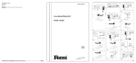
UK
Subject to change
Document Ref:
FBF-1050E
Copyright ©
These instructions are the sole property of Ferm-Omega Safes and may not be reproduced
Ferm BV • P.O. Box 134 • 8280 AC Genemuiden • NL • www.ferm.com
0309-24
Ferm Plunge Router
FBF-1050E
USER’S MANUAL
Art.nr. 726195
Fig. B
Fig. A
Fig. G
Fig. F
Fig. E
Fig. D
Fig. C
2
Ferm
EXPLODED VIEW
Ferm
11
10
REF NR
4
5
6
8
9
17
18
19
23
27
28
31
33
34A
34A
35
36
39
42
43
44
46
47
51
54
55
57
62
72
73
74
78
79
80
81
82
84
86
87
SPARE PARTS LIST FBF-1050E
DESCRIPTION
SPEED REGULATOR
DEPTH KNOB
COPPE BUSH
BRUSH HOLDER
ENCLOSURE
SWITCH
PULL-BACK BAR
SWITCH ACTUATOR
STATOR
BEARING 60018
ROTOR
BEARING 80103
SPRING FOR COLLET
COLLET
COLLET
CHUCK NUT
RUBBER CAP FOR HANDLE
LOCKING LEVER
GEAR
BLOCK STOP
SPEED REGULATOR
RACK BAR
HANDLE
ROTARY SWITCH
PAWL SPRING
BRAKE RACK
BUTTON FOR BRAKE RACK
DUST TUBE
SCREW
SPING
PLASTIC BOTTOM PLATE
ROD B
ROD A(WITH SCALE)
GUIDE FRAME
SPRING WASHER
HOLLOW-HEAD SCREW
PLASTIC LINER
WRENCH
SCALE PLATE
FERM NR
302100
302101
312004
312004
312002
302057
302102
302103
302104
800608
302105
806003
302106
312008
312012
312009
302058
302002
302107
302107
302107
302108
302058
302109
302110
302110
302110
302111
302112
302112
302113
302005
302005
302114
302005
302005
302115
312011
302107
Ferm
PLUNGE ROUTER
THE NUMBERS IN THE FOLLOWING TEXT
CORRESPOND WITH THE PICTURES AT PAGE 2
|
|
|
|
|
|
|
|
|
|
|
230 V~
50 Hz
1050 W
9000-30000
30 mm
30 mm
6 & 8 mm, 1/4”
3.28 kg
89.0 dB(A)
102.0 dB(A)
4.3 m/s2
TECHNICAL SPECIFICATIONS
Voltage
Frequency
Power input
No load speed/min
Max. cutter diameter
Cutting depth
Collet
Weight
Lpa (sound pressure)
Lwa (sound power)
Vibration value
PACKAGE CONTENTS
1 Router
1 Parallel guide
1 Template guide
2 Screws
2 Nuts
1 Adapter for dust extraction
1 Dust tube
1 Wrench
1 Instruction manual
1 Guarantee card
Check the machine, loose parts and accessories for
transport damage.
PRODUCT INFORMATION
Fig. A
The FBF-1050E router has been designed for
professional routing of wood, wood products and
plastics.
1 On/off switch
2 Handle
3 Router base
4 Locking bolt for parallel guide
5 Opening for parallel guide
6 Collet nut
7 Spindle lock
8 Revolver-depth stop
9 Locking bolt depth stop
10 Depth stop
11 Clamping lever
12 Scale cutting depth
13 Adjusting wheel electronic speed control
14 Height adjusting button
15 Adapter for extracting dust
16 Dust outlet
Ferm
SAFETY INSTRUCTIONS
The following symbols are used in these instructions for
use:
Denotes risk of personal injury, loss of life or
damage to the tool in case of non-observance of
the instructions in this manual.
Denotes risk of electric shock.
Carefully read this manual before using the machine.
Make sure that you know how the machine functions and
how to operate it. Maintain the machine in accordance
with the instructions to make sure it functions properly.
Keep this manual and the enclosed documentation with
the machine.
Ferm products are manufactured to high quality
standards they are safe and fit for purpose at time of sale,
but all tools can be dangerous if the correct precautions
are not taken. Always follow these instructions, do not
carry out the operation until you are sure you can do so
in safety. Remember to consider the work environment
for safe operation as well as safety for tool use.
Warning! When using electric tools, basic safety
precautions should always be followed to reduce
the risk of fire, electric shock and personal injury. Read all
these instructions before attempting to operate this product.
Save these instructions for future reference.
PERSONAL SAFETY
Use Personal Protection Safety Equipment
Protect eyes with safety glasses or goggles note: the use
of safety protective eyewear without the CE mark can
lead to serious injury if the lens breaks. A suitable dust
mask should be worn if cutting, drilling or sanding is
dusty, in particular chipboard or MDF.
Approved safety footwear and headgear should worn as
appropriate, for example on building works or when
heavy weights are involved. Wear suitable gloves and
apron to protect against sparks/debris. Wear earplugs
or ear defenders.
Dress properly
Do not wear loose clothing or jewellery. It can get
caught in moving parts. Non-skid footwear is
recommended when working out doors. Wear
protective hair covering to contain long hair.
Stay alert
Watch what you are doing Use common sense. Do not
operate tools when tired or after taking alcohol or
prescription/ non-prescription drugs.
3
OPERATIONAL SAFETY
Warning! Be aware this planer can produce fine
dust, which can be hazardous to your health.
Always use a suitable mask, eye protection, and other
personal protection equipment. Use dust extraction during
working and cleaning.
Concentrate
Routine and repetition can lead to mistakes. Remember
that a slight lack of concentration can result in serious
injuries in a split second.
Keep work area clean
Cluttered areas and benches invite injuries.
Consider the work environment
Do not expose power tools to rain or use them in damp
or wet locations. Keep work area well lit. Do not use
power tools in the presence of flammable liquids,
vapours or gases.
Guard against electric shock
This unit contains dangerous voltages. Use a RCD
(residual current device) to provide protection against
electrical shock. Prevent body contact with grounded
surfaces (e.g. pipes, radiator, ranges or refrigerators).
Keep children and pets away
Do not let children or pets come into contact with the
tool, extension cable or work area.
Do not force the tool
It will work better and safer at the rate for which it was
intended.
Use the right tool
Do not force small tools or attachments to do the job of
a heavy-duty tool. Do not use tools for purposes for
which they were not intended; for example do not use a
circular saw for cutting trees or logs.
Do not abuse the cable
Never carry the tool by the cable or pull it to disconnect
it from the power socket. Keep the cable away from
heat, oil and sharp edges. Do not touch the metal plug
pins when connecting or removing the plug.
Do not over-reach
Keep a proper footing and balance at all times.
Disconnect tools from power supply
When not in use, before servicing and when changing
accessories such as blades, bits and cutters.
Always switch off and unplug the planer from the
power supply before making adjustments or
changing belts.
Remove adjusting keys and wrenches
Ensure that they are removed from the tool before
switching on.
4
Avoid unintentional starting
Do not carry plugged in tools with your finger on the
switch. Check that the switch is off before plugging in to
socket.
Extension cables
Use only three core earthed extension cables suitable
for the power input of the tool (minimum cable size
1.5mm2). Plug into an earthed socket only.
When using a cable reel unwind it fully. Do not use long
extension cables.
Outdoors use
If the tool is suitable to be used outdoors, only use an
extension cable intended for outdoor use and marked
accordingly. Use a RCD (residual current device) to
provide protection against electrical shock. Do not use
in rain or damp conditions.
Connect a dust extraction device
Whenever there are facilities for fitting a dust or fume
extraction system, make sure it is connected and used.
Use recommended accessories
The use of an accessory or attachment other than
recommended in the instructions or catalogue may
present a risk of personal injury. Use an extension cable
with a minimum conductor size of 1.5mm2.
When using a cable reel unwind it fully.
Ferm
Ferm
9
8
Ferm
MOUNTING ACCESSORIES
Prior to mounting an accessory always unplug the tool.
Wait until the machine has come to a complete
standstill and the cutter has cooled down before
replacing a cutter.
MOUNTING AND REMOVING CUTTERS
Fig. B
Only use cutters with a shaft diameter which
corresponds with the size of the collet. Only use cutters
which are suited for the maximum speed of the machine.
The cutter diameter should not exceed the maximum
diameter (see ‘Technical specifications’).
• Press the spindle lock (7) and turn the collet nut (6)
until it engages in the lock. Keep the spindle lock
pressed during this procedure.
• Open the collet nut using the wrench.
• Place the cutter shaft in the collet.
• Tighten the collet nut so that the cutter is locked
properly.
Open the collet nut when you want to replace a cutter.
•
MOUNTING AND ADJUSTING THE
PARALLEL GUIDE
Fig. C
The parallel guide is a handy aid when working on
narrow workpieces.
• Mount the parallel guide. Attach the guide rods (18)
on the frame (17) using the bolts (19).
• Loosen the locking bolts (4) and slide the guide rods
in the openings (5).
• Adjust the parallel guide to the desired guide
distance.
Tighten the locking bolts again.
•
MOUNTING THE GUIDE BUSH
Fig. D
The guide bush is a handy aid for cutting a pattern.
• Mount the guide bush (20) on the router base (3)
using the screws (21).
Keep the outlet of the machine behind the machine
for a good view on the workpiece.
MOUNTING THE ADAPTER FOR DUST
EXTRACTION
Fig. E&F
Use the dust adapter for the extraction of dust.
• Mount the dust adapter (15, Fig. E) with the screws
(21) on the cutter sole (3).
Place the dust tube (62) in the dust output (16 Fig. F).
Place the tube of your vacuum cleaner on the dust
tube (62, Fig. F)
•
•
Ferm
OPERATION
Always observe the safety instructions and
applicable regulations.
Hold the machine in rest position on the workpiece when
switching the machine on or off. The cutter in the collet may
damage the workpiece.
• Clamp the workpiece and make sure that the
workpiece cannot slide from under the machine during
the cutting activities.
• Hold the machine firmly and move it evenly over the
workpiece. Do not force the machine.
• Only use cutters which do not show any signs of wear.
Worn cutters have a negative effect on the efficiency of
the machine.
Always switch off the machine first before removing the
plug from the wall socket.
•
ADJUSTING THE CUTTING DEPTH
Fig. F
The cutting depth can be adjusted in three ways.
Adjustment using the height adjusting button
• Use the height adjusting button (14) to set a fixed
cutting depth. Rotate the button clockwise to lower the
machine’s height; rotate the button counterclockwise
to raise the machine’s height.
Adjustment using the scale
• Loosen the locking bolt of the depth stop (9).
• Release clamping lever (11) and press the machine so far
down until the cutter touches the workpiece.
• Tighten the clamping lever again.
• Lower the depth stop (10) completely by rotating the
button counterclockwise.
• Tighten the locking bolt.
• Rotate the scale (12) to 0 position (arrow indicating 0).
• Loosen the locking bolt.
• Set the required cutting depth using the scale (12) and
the depth stop (10)
Tighten the locking bolt.
Release clamping lever.
•
•
Adjustment using the revolver- depth stop
The revolver-depth stop enables you to quickly choose
between six different cutting depths. These are also
determined by the adjustment of the depth stop (10).
• Adjust the required cutting depth by rotating the
revolver-depth stop (8).
SWITCHING ON AND OFF
Fig. A
• To switch the machine on, you press down the on/off
switch (1) using your thumb. You can adjust the cutting
speed by turning the adjusting wheel (13).
To switch the machine off, you release the on/off switch
by pressing the side of the switch using your thumb.
•
Always select a low speed for cutting plastic
workpieces.
Do not put the machine down when the motor is still
running. Do not place the machine on a dusty surface.
Dust particles may enter the mechanism.
5
MAINTENCE, CARE AND REPAIR
Switch off and unplug the machine before carrying
out any cleaning or maintenance work.
CLEANING
Wear personal protection equipment during cleaning.
Do not use water or flammable liquids to clean the
planer, clean with a soft brush.
FAULTS
Should a fault occur, e.g. after wear of a part, please
contact your local Ferm dealer.
In the back of this manual you find an exploded view
showing the parts that can be ordered.
LUBRICATION
The machine requires no user lubrication.
MAINTAIN TOOLS WITH CARE
Keep the tool clean for better and safer performance.
Follow instructions for changing accessories. Inspect
tool and extension cables periodically and if damaged,
have them repaired by a qualified person or authorised
service body.
Check for damaged parts
Do not use a tool with damaged parts, before further use
a damaged tool must be carefully checked by a qualified
person to determine that it will operate properly. Check
for alignment of moving parts, binding or breakage of
parts, mounting and other conditions that may affect its
operation.
A damaged part or guard should be properly repaired by
an authorised service centre, unless indicated otherwise
in the instruction manual. Have defective switches
replaced by an authorised service centre. Do not use a
tool if the switch does not turn on and off.
Have your tool repaired by an expert
This appliance is manufactured in accordance with
relevant safety standards. Only experts must carry out
repairing of electrical appliances, otherwise
considerable danger for the user may result.
Storing tools
When not in use tools should be stored in the dry, out of
reach of children.
6
ELECTRICAL INFORMATION
This product is complete with a pre-wired mains plug, if
the plug needs replacing follow these instructions.
This planer is double insulated in accordance with EN
50144 therefore no earth wire is required.
Brown
(Live)
Fuse
(13 Amp)
Wire correctly
The wires in the mains lead are coloured in the following
way:
BLUE
• Neutral
BROWN • Live
Green & Yellow
(Earth)
Blue
(Neutral)
Securing wires
Secure wires carefully and firmly to the correct
terminals. Secure the mains cable in the plug cord grip
firmly
Fit a 13-amp fuse. If a 5-amp (BS1362) plug is used a
(BS1363) ASTA approved 13-amp fuse must be fitted
Recycle/Dispose of old plug and cable
Prevent inadvertent connection to socket and risk of
electric shock.
ENVIROMENT
Recycle the packaging according to the identification
marks on it.
At the end of the product or its accessories life please
recycle where facilities exist. Phone the Helpline for
current advice on recycling.
Helpline
For any questions relating to operational or safety
matters contact:
Ferm Customer Helpline on: 0115 966 1199
Monday-Friday
8am – 6pm
Saturday
9am – 1 pm
Ferm
DECLARATION OF CONFORMITY
(UK)
GUARANTEE
The guarantee conditions can be found on the separately
enclosed guarantee card.
Wear of the cutter is not covered by the guarantee.
CEı
We declare under our sole responsibility that this
product is in conformity with the following
standards or standardized documents
EN50144-1, EN50144-2-17,
EN55014-1, EN55014-2,
EN61000-3-2, EN61000-3-3
in accordance with the regulations.
98/37/EEC
73/23/EEC
89/336/EEC
from 26-11-2002
GENEMUIDEN NL
W. Kamphof
Quality department
Ferm
7