1
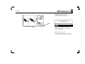
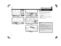
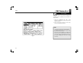
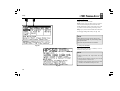
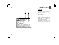
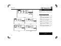
HPS50 PersonalScopeTM PERSONALSCOPE tm English 1 HPS50 PersonalScopeTM Contents CONTENTS Velleman Components Legen Heirweg 33 9890 Gavere Belgium Internet Site: http://www.velleman.be HHPS50 - ed1 - 2009 General ............................................................... 6 Features................................................................ 6 Options ................................................................ 6 Safety and warnings........................................... 8 Power supply .................................................... 12 Use..................................................................... 12 Survey of the connections and controls ............. 12 Survey of the indications on the screen.............. 14 Operation.......................................................... 16 Turning on/off the Personal Scope..................... 16 Adjusting the contrast ........................................ 18 Display setup ..................................................... 20 Setup menu ........................................................ 22 Operating mode............................................ 24 Power-off mode ............................................ 24 Display mode................................................ 26 Send mode .................................................... 26 Readout setup .................................................... 28 Probe setup ........................................................ 38 The signal Markers ............................................ 40 Signal Screen ..................................................... 44 Choice of input coupling.................................... 46 Set the input reference ....................................... 46 Auto-Setup function........................................... 48 Input sensitivity & Timebase ............................. 50 Trigger setup...................................................... 52 Holding the screen ............................................. 60 Store a screen..................................................... 60 Recall memories ................................................ 62 Sending a screen capture ................................... 62 Resetting the personal scope ........................... 64 Troubleshooting ............................................... 66 Warranty .......................................................... 68 Maintenance ..................................................... 68 Technical specifications ................................... 71 2 HPS50 PersonalScopeTM General GENERAL Features Fig 1.0 Fig 2.0 • • • • • • • • • • • • • • • ultra fast full auto set up option adjustable trigger level X and Y position signal shift DVM readout audio, power calculation (rms and peak) dBm, dBV, DC, rms ... measurements signal markers for voltage and time frequency readout (through markers) recorder function (roll mode) signal storage (2 memories) high-resolution LCD with backlight galvanically separated USB output for PC data or bitmap download to PC different screen modes USB PC Connection real-time and screen capture Included: • worldwide adaptor (Fig. 1.0) • USB cable (Fig. 3.0) • insulated measurement probe x1/x10 (Fig. 4.0) Fig 3.0 Fig 4.0 3 HPS50 PersonalScopeTM Safety & Warnings Symbols displayed on the unit - Symbolen op het toestel - Symboles sur l'appareil - Symbole auf dem Gerät SAFETY & WARNINGS ⇒ The PersonalScope is ideally suited for measurements of category II installations with pollution degree II and using a maximum of 600V, in accordance with the IEC1010-1 norm. ! Important safety information, see user manual. Belangrijke veiligheidsinformatie, zie gebruiksaanwijzing. Information importante relative à la sécurité, voir mode d'emploi Wichtige Sicherheitsinformationen, siehe Gebrauchsanleitung. ⇒ Consequently, all measurements should be avoided in case of polluted or very humid air. One should also refrain from measuring conductors or installations that use voltages that exceed 600Vrms above ground level. CAT II indicates conformity for measurements of domestic installations. ⇒ The maximum input voltage for the connections of the unit stands at 100Vp (AC+DC) ⇒ Do NOT open the enclosure while performing measurements. ⇒ Remove all test leads before opening the enclosure in order to avoid electrical shock. ⇒ Use a measuring probe with an insulated connector when measuring voltages exceeding 30V. (PROBE60S). 4 HPS50 PersonalScopeTM Safety & Warnings ⇒ When first using the unit or if the batteries are Fig. 3.0 completely discharged, the user should charge them for at least 10 hours before using the unit. ⇒ The “Charge” indication LED on the top panel will light up when the batteries are being charged (see fig.3.0). The message “Low bat.” will flash in the bottom right corner of your display when the batteries need charging. Insufficient battery voltage may entail erroneous measuring results (see fig.4.0). Fig. 4.0 5 HPS50 PersonalScopeTM Power supply POWER SUPPLY The HPS50 Personal Scope can be powered by means of the supplied adapter or with the internal lithium Ion battery (7,4V/1050mAh). 4 USE Fig 8.0 Survey of the connections and controls 1. BNC input connector (max. input 100Vp AC+DC). 2. Adapter connection (observe the polarity!) Fig 5.0 3. USB output connector (galvanically separated) Use the supplied USB cable 5 Fig 9.0 4. Reset push button 5. X10 probe testing signal 6. Serial number. 3 2 1 Fig 7.0 6 Fig 10 6 HPS50 PersonalScopeTM Screen 4 Survey of the indications on the screen 5 6 7 2 8 9 10 3 Fig 9.0 1 14 15 11 Fig 10 13 12 REMARK: The screen depends on selected layout. See page 20 OPMERKING : De schermuitlezing is afhankelijk van de gekozen weergave. Zie pagina 20 REMARQUE : l'écran dépend de la présentation choisie. Voir page 20 BEMERKUNG : Die Schirmanzeige hängt von der gewählten Wiedergabe ab. Siehe Seite 20 7 1. Relative position indication of the signal in the window. 2. Trigger position and slope indication 3. Signal window with (possibly) the markers or grid to indicate the various divisions. 4. Time per division. 5. Time between markers (if present). 6. Calculated frequency 1/dt between markers (if present). 7. Voltage between the markers (if present). 8. Measurement readout (maximum 4 at a time). Depending on screen layout. See page 20 9. Trigger information or screen hold indication, input-coupling indication. 10. X1 or X10 probe setup indication. 11. Selected voltage per division. 12. Indication of the selected cursor key function or battery-low indication. 13. Small dots indicating relative marker position (only if markers are present). 14. Vertical position of the signal on the screen 15. Slope indication HPS50 PersonalScopeTM Operation OPERATION NOTE: - If functions are used together with cursor keys a short indication will pop up at the right bottom of the screen. - Some keys have double function selected with a long --- or short press. - In most selections, the unit will return to the default t-V/div mode if no key is pressed during 10 sec, a selection will be canceled. 1 POWER ON/OFF Short press: On (Off) with auto power off timer. (1) Long press: On without auto power off timer. (2) NOTE: • Pressing a key resets the auto power off timer. • The power-off mode is displayed at the bottom of the screen during startup. • The last signal will be saved when the "HOLD" 2 8 setting was chosen before powering off the device. HPS50 PersonalScopeTM Operation After power on, the unit will send the current data through the USB port (1), see fig. 11 : 1) settings and samples stored in memory. 2) settings and samples of the screen. Download software from our web site www.velleman.eu 1 ADJUSTING THE CONTRAST Fig 11 Short press: Backlight high/low intensity. Remark: the backlight intensity will diminish 1 minute after the last key press. Long press: Change the contrast. Keep pressing the ‘Contrast’-key to change the contrast. Release the button at the desired setting. 9 HPS50 PersonalScopeTM Display Display Setup DISPLAY SET-UP Short press: Use the left/right cursorkeys to select one of the 5 screen layouts (see fig. 12 to 16). Use the up/down cursorkeys to view/hide the markers or grid on the screen. Fig 12 Fig 13 • A dot grid divides the screen into reference points. (Fig. 14) • A full grid divides the screen into reference lines. (Fig. 15) • Markers: Moveable markers in order to measure the signal (Fig. 16). NOTE: Fig 14 Fig 15 • The number of readout-digits depends on the selected display layout. • At dynamic display mode (see display setup), the display layout changes for best fitting when shifting the markers or x-position. • When no markers are displayed, the cursor keys are set for changing the time base or input sensitivity when no keys are pressed during 10 seconds. • Markers can also be accessed directly by pressing the ‘Marker 1-2’ key. Fig 16 10 HPS50 PersonalScopeTM Setup Display Setup SETUP MENU Long press: Shows a setup menu for changing the operation mode, the default power-off timer, the display mode. 1. Select the highlighted item with a short keypress of the setup-key and by using the up/ down cursor keys 2. Keep the setup-key pressed to exit the setupmenu and to apply the selections. NOTE: • A checkmark indicates the current selection. • Leaving the mode menu with the ‘power off’ key will cancel the selection. • If no key is pressed during 10 seconds, the Fig 17 11 selection will be cancelled, the unit returns to it previous operating mode and the cursor keys are set for changing the time base or input sensitivity. HPS50 PersonalScopeTM Setup 1 1. Operating mode : 2 Scope: normal operation mode. Demo: Scope goes into demo mode; several animated screens are displayed one after the other. Y-cal. calibrate the centre of the signal; only if the Y position is incorrect during Auto set-up mode. Help: display of the version number and a short note on the trigger settings and memory use (fig. 18b). NOTE: Hiding the help screen can only be done by long keypressing of the ‘Setup’-key and choosing a different operation mode. Most of the keyboard functions are disabled. Fig 18a 2. Auto power-off mode : Select the desired off time: 15 minutes, 1 hour or infinite (no auto power off). NOTE: • Before power-off, the scope holds the last screen. • The auto power-off timer is factory-set to 15min at first power-on or after a reset • Selecting a slow time base (equal or slower than 1min/div) will disable the auto power off. Fig 18b 12 HPS50 PersonalScopeTM Setup 3. Display mode 3 4 Dynamic: The screen layout changes automatically to show the best signal resolution, depending on X position shift and the position of the markers. See also “using the markers” Manual: The screen layout remains fixed ding to your selection. accor- 4. Send mode ASCII: a file with settings and samples (relative value 0 to 255) is send after power on or during roll mode. This setting is normally used in conjunction with a terminal program. Binary: As above, but data are output in a binary form. Use this setting with special software, check our web site. Fig 19 13 HPS50 PersonalScopeTM Meter readout READOUT SET-UP Press to call the meter 1 to 4 selection menu. Make use of the cursorkeys to set a readout for up to 4 meters Setting up the measurement readouts: Fig 20 Fig 21 Fig 22 Fig 23 Fig 24 1. Pressing the ‘meter’-key selects the first readout location. 2. Press the cursorkeys to highlight the desired readout function for meter 1 readout. (Fig. 21) 3. Pressing the ‘meter’-key selects the second readout location 4. Press the cursorkeys to highlight the desired readout function for meter 2 readout. (Fig. 22) 5. Pressing the ‘meter’-key selects the third readout location 6. Press the cursorkeys to highlight the desired readout function for meter 3 readout. (Fig. 23) 7. Pressing the ‘meter’-key selects the fourth readout location. 8. Press the cursorkeys to highlight the desired readout function for meter 4 readout. (Fig. 24) 9. Pressing the ‘meter’-key returns to scope mode. The Personal Scope offers many measuring possibilities. 14 HPS50 PersonalScopeTM Meter readout 1. DC voltage measurement (V=). This function enables the user to measure DC voltages (only for DC input coupling) 1 6 2. Maximum voltage (Vmax.). The signal's positive peak voltage (difference between zero and highest value) is displayed. 5 2 3. Minimum voltage (Vmin.). The signal's negative peak voltage (difference between zero and lowes value) is displayed. 3 4. Peak to peak (Vpp). The signal's peak-to-peak voltage (difference between highest and lowest value) is displayed. 4 5. True RMS readout (Vrms ac) The true RMS value of the AC wave is calculated and converted to voltage. Fig 25 Useful tip for measuring DC voltages: The readout can be set at zero (reference) for any position on the screen by keeping the AC/DC key pressed down. Always use the "run" trigger mode for DC voltage measurement. 15 HPS50 PersonalScopeTM Meter readout 6. dBV measurement (dBV ac). The measured signal (ac only) is converted to dBv (0dB= 1V). 9 10 7. dBm measurement (dBm ac). The measured signal (ac only) is converted to dBm (0dB= 0.775V). 8. dB measurement (dB ac). The measured signal (ac only) is converted to dB (0dB= dBref*) 9. True RMS readout (Vrms ac+dc) The true RMS value of the wave (ac+dc) is calculated and converted to voltage. 10. dBV measurement (dBV ac+dc). The measured signal (ac+dc) is converted to dBv (0dB= 1V). 11. dBm measurement (dBm ac+dc). The measured signal (ac+dc) is converted to dBm (0dB= 0.775V). 12. dB measurement (dB ac+dc). The measured signal (ac+dc) is converted to dB (0dB=dBref*) Fig 26 8 7 12 11 *dB ref Select dBref to set the user defined reference for dB measurement, the selected meter will be set for dB measurement 16 HPS50 PersonalScopeTM Meter readout Audio power calculation. The measured voltage is converted into power, suposing that the voltage is measured across an impedance. The calculated power can be displayed for loads of 2, 4, 8, 16 or 32 Ohm. To choose the different loads, first highlight the power readout and then press the right cursor key. 13 14 13. W ac AC Rms power calculation into selected impedance 15 14. W peak Peak power calculation into selected impedance. 15. W ac+dc AC+DC power calculation into selected impedance (a normal audio signal can not have DC component). Fig 27 17 HPS50 PersonalScopeTM Meter readout Notes: • If the signal goes off-screen or when the signal is too small for measurement, the readout will show ??? (see fig 28) Fig 28 • For all AC measurements: Make sure that at least one or two periods are displayed or select the auto-setup function. • You can choose “none” to hide readouts. • Depending on the selected screen layout one to four different meter readouts can be displayed. • At 1s/div timebase or slower, the readouts are forced to the instant information. ‘Vs’ (Fig. 29) . • If no key is pressed during 10 seconds, the unit returns to its previous operating mode and the cursorkeys are set for changing the timebase and sensitivity. Fig 29 18 HPS50 PersonalScopeTM Probe setup x1 x Probe x1 / x10 10 PROBE SETUP Press the ‘Probe x1/x10’-key to set the measurements accordingly the x1/x10-probe setting. (Fig. 30) x1 0 x1 Notes: • Automatically calculate the correct readouts depending the x1 or x10 probe setting. • An ‘x10’ symbol is displayed if this mode has been selected. • X10 measuring probes should be calibrated! • IMPORTANT: Set the measuring probe in the x10 position for measuring high voltages (>100Vp+dc) Fig 30 Setting up a X10 measuring probe : Fig 31 When used in the X10 position, a measuring probe should always be calibrated to the measuring instrument being used, in this case the Personal Scope. (Fig. 31) • Set the scope to X10 position (probe x1/x10 key). • Set the voltage per division to 1V. • Set the time per division to 0,1ms. • Select AC for the input. Fig 32 19 Use the probe to perform measurements at the preselected point. Adjust the trimmer of the measuring probe in order to obtain a square wave signal with a top that is as flat as possible (Fig. 32) HPS50 PersonalScopeTM Markers Marker 1- 2 THE SIGNAL MARKERS The user can perform measurements on a certain signal by using the four moveable markers. This can be useful when measuring the interval between two points or the amplitude of any given peak. 1 2 3 The following indications will appear on the screen : 1. The time interval between two vertical markers. 2. The calculated frequency 1/∆t (primarily used for the measurement of periods). 3. The voltage between two horizontal markers. 4. Small dots indicating relative marker position on the complete signal. Fig 33 4 The markers can be moved through the arrow keys. Keeping the key pressed down will move the marker quickly, pressing it briefly will move the marker by 1 position. The “mark 1-2” key is used to select the desired marker. 20 HPS50 PersonalScopeTM Markers Determining the frequency of a signal requires the measurement of a period. The easiest way to do this would be by placing the vertical markers either on two consecutive peaks or two identical slopes of a signal. 1. 2. Press the “Marker 1-2”-key to view, select or hide the markers. (1) Press the cursur keys to move the markers. (2) Notes: 1 2 Fig 34 21 • By pressing the ‘Marker 1-2’-key, you select between marker 1 or 2. The screen shifts automatically until the selected time marker is on screen. • At dynamic display mode (see display setup), the best display layout is chosen depending the use of time markers or voltage markers. • Some meter readouts are replaced by the marker readouts. • Depending on the chosen display layout, not all of the marker readouts can be displayed at the same time. • Removing the markers from the screen can be done by repeatedly pressing the ‘Marker 1-2’-key or by a short press of the ‘Display’key and using the up/down cursor keys. HPS50 PersonalScopeTM Signal position X/Y - pos SIGNAL SCREEN Press first the ‚X/Y-pos‘ key before pressing the arrow keys in order to move the signal in the direction of the arrows. Prolonged pressing will make the X or Y- position change faster. A black bar (1) indicates the relative position of the signal in the sample window, see fig. 35 1 Notes: Fig 35 22 • The Y-position cannot be shifted in ‘hold’mode • A total of 256 samples are stored in memory, but the X-size of the screen is limited. By shifting the X-direction you can display all stored samples. • At dynamic display mode (set-up menu), the widest display layout is chosen by shifting the x-position. • When no markers are displayed, the cursor keys are set for changing the time base or input sensitivity when no keys are pressed during 10 seconds. HPS50 PersonalScopeTM Signal position AC/DC Gnd CHOICE OF INPUT COUPLING Short press: Choice of input coupling AC (3) or DC (2). Depending on (part of) the signal to be measured, the input can be connected to the signal through a direct link or by using a decoupling capacitor. Select DC for measuring DC voltage. Press the “AC/DC” key to select either AC or DC input coupling (see indica-tions on the screen). Fig 36 2 Note: At time bases of 1s/div and slower, the input coupling is DC-only. AC/DC Gnd SET THE INPUT REFERENCE Long Press: Switches the scope input to ground and stores the trace position as a new dc zero reference. Use this function to find and set the zero DC-reference trace on the screen. Fig 37 3 23 When measuring the ”ripple” on a DC voltage : put the input on AC to limit the measurement to the AC component of the signal. HPS50 PersonalScopeTM Auto-setup Auto AUTO-SETUP FUNCTION The auto-setup function is ideally suited for quick measurements as no manual setup has to be made and everything is automatic. Note: Use the auto-setup function when the screen no longer displays a signal after the manual setup. Fig 38 Autorange on (Fig. 38) : • Time/div and Volt/div settings are displayed inverted. • The time base and input sensitivity are automatically set for optimal viewing of the input signal. • Auto-triggering is set for time base 2µs/div or slower. • Normal triggering is set for time base faster then 2µs/div. • The slowest possible time base is 5ms/div. • The fastest possible timebase is 250ns/div. • Y-position is set to the center location. Autorange off (Fig. 39) : • Time/div and Volt/div settings are displayed in a normal font (not inverted). • Cursor keys are set for changing the time base and input sensitivity. Fig 39 24 Note: Changing the time base, input sensitivity, Y-pos or trigger mode turns off the auto range-mode HPS50 PersonalScopeTM Input sensitivity t-V/div CHANGING THE INPUT SENSITIVITY AND TIMEBASE First press the „t-V/div“ key (1), use up/down cursorkeys (2) for changing the input sensitivity (V/div) (Fig 40). Press the left/right (3) cursorkeys for changing the timebase (time/div). (Fig 41) 1 1 1. Changing Volt/div (Fig. 40): The signal on the screen can be enlarge or reduce vertically by adjusting the displayed voltage per division. (V/div = voltage per division). The divisions can be made visible through the Display setup key (see display setup). Select the sensitivity : from 5mV to a maximum of 20V per division. 2 3 50mV to 200V with X10 probe selection • Pressing the up cursor key increases the input sensitivity (lower value for V/div). • Pressing the down cursor key decreases the input sensitivity (higher value for V/div). 2. Changing the timebase (fig. 41): Fig 40 Fig 41 Adjusting the time base will visualise more or fewer periods of a signal (t/div = time per division). The divisions can be visualised through the display set-up key (see display setup). Set the time base between 1h and 50ns per division. • Press the ‘t-V/div’-key to set the cursorkeys action into ‘timebase’ mode. • Press the ‘left’ or ‘right’ cursor keys to increase or decrease the timebase (time/div). 25 HPS50 PersonalScopeTM Trigger function Note: • Changing the timebase or sensitivity switches the autorange mode immediately off. (Fig 42) • The timebase or sensitivity cannot be changed into hold mode. • Pressing the ‘t-V/div’ key into hold mode 1 Fig 42 toggles the screen between the two stored waveforms. • At higher timebase (1µs and faster) the scope uses oversampling mode, only repetitive signals are correctly displayed. • Use the minimum time base (250ns) as a starting point when measuring a signal and select longer time bases until the signal is displayed properly. Otherwise the display may not correctly reflect the signal under measurement due to aliasing. trig THE TRIGGER SETUP • Press the „trigger“-key. • Change the triggermode (norm, run, once or roll). • Use the left cursorkey to toggle the trigger slope • Use the up/down cursorkeys to shift the vertical trigger position (1). • Use the right arrow key to force a manual trig- gering. 26 HPS50 PersonalScopeTM Trigger modes Trigger modes : ”norm” = Normal trigger A triggering (or manual trigger) must occur before the sample memory is filled. Use this mode when you want to start displaying the signal when it reaches a preset threshold value. (Fig 43) Fig 44 Fig 43 Trigger gab - Trigger opening - Niveau de démarrage - Triggeröffnungsanzeige “run” = Auto-trigger mode The scope automatically triggers if no triggering occurs for a fixed period of time. This position is used most frequently and should always be used for measuring DC voltages in particular. (Fig 44) “once” = Sampling starts after a trigger. Afterwards, the scope switches to ‘HOLD’-mode. Use this mode to detect e.g. a short, once-only voltage peak. (Fig 45). Press “memory” repeatedly for a new triggering. “roll” = Roll-mode, available for timebases of 1s/div or slower. Sampling is continuous and the screen starts rolling as soon as it is full. Use this position for “recording” slow moving dc signals. (Fig 46) Fig 45 27 Fig 46 Notes: • Pressing the Right cursor key generates a manual triggering (except in ‘HOLD’-mode) • Changing the trigger mode switches the autorange mode immediately off. • At time base of 1s/div and slower, the input coupling is DC-only • Normal triggering is the only triggermode for timebases of 1µs/div or faster because of the oversampling method. • Keep pressing the trigger key during “hold” mode stores the current screen into memory. • When no markers are displayed, the cursorkeys are set for changing the timebase or input sensitivity when no keys are pressed during 10 seconds. HPS50 PersonalScopeTM Trigger Trigger slope : Press the left cursor key to set triggering at the rising or falling edge of the input signal. 1. Triggering on the rising slope of the signal : The screen will only display the signal when a positive slope is "detected", viz. the signal has to rise in vertical direction in order to trigger. (Fig 47) 1 Fig 47 2. Triggering on the falling slope of the signal: The screen will only display the signal when a negative slope is "detected", viz. the signal has to drop in vertical direction in order to trigger. (Fig 48) Notes: 2 • Between triggering and the first sample- Fig 48 aquisition there is a fixed hardware-determined delay. Because of this delay, the sampled signal can show a different slope at fast timebases. • When no markers are displayed, the cursorkeys are set for changing the timebase or input sensitivity when no keys are pressed during 10 seconds. 28 HPS50 PersonalScopeTM Trigger Changing the trigger level : Press the ‘Trigger’-key to set the cursorkeys action into ‘trigger’ mode. • Press the up/down arrow keys to move the trigger level (1). • Notes: 1 When no markers are displayed, the cursorkeys are set for changing the timebase or input sensitivity when no keys are pressed during 10 seconds. Fig 49 29 HPS50 PersonalScopeTM Screen memory Memory HOLDING THE SCREEN Press the ‘Memory’-key to freeze the waveform on-screen. It may be useful to "freeze" certain signals on your screen. This will allow the user to study the signal using the markers. (Fig 50) Remarks: 1 • Most of the keyboard functions are disabled. • Pressing the Memory key immediately stops sampling at slow timebases. The rest of the sample buffer will be cleared. • ‘HOLD’ will be displayed inverted. (1) • Releasing the ‘Hold’-mode will remove the waveform from the screen. Fig 50 Memory STORE A SCREEN • Press the Memory key to “Hold” the waveform on-screen. • A long keypress of the ‘Trigger’-key mode stores the current screen into memory. (2) Fig 51 30 2 HPS50 PersonalScopeTM Screen memory t-V/div RECALL MEMORIES Pressing the ‘t-V/div’-key when in hold mode toggles the screen between the frozen waveform and the stored waveform. ‘Mem’ is displayed if stored waveform is visible. (1) Notes: Fig 52 • The store and recall function is only available in ‘HOLD’-mode • All setting such as timebase, input sensitivity, input coupling, probe setting and readouts are also stored into memory. 1 Memory SENDING A SCREEN CAPTURE TO THE COMPUTER It is possible to send a screen picture to your computer using the USB output. During „Hold“ mode press and keep pressing the memory key. A screen bit map (BMP) file will be send to the computer. A capture program can be downloaded from our site. During normal measuring, press and hold the „memory“ key, to capture the screen. Fig 53 2 31 „Transmit“ (2) is displayed briefly during the file transmit. (Fig.53) HPS50 PersonalScopeTM Resetting RESETTING THE PERSONAL SCOPE Press the sunk (1) ‘Reset’ push button for at least 10 seconds to return to the manufactureprogrammed setup. Note: • Use the reset function in case of unusual behaviour of the unit, like distorted screen or not functional keyboard (see also troubleshooting). • Do not use a sharp tool. 1 Fig 54 32 Troubleshooting HPS50 PersonalScopeTM TROUBLESHOOTING The screen remains blank or there is no signal : • No power supply • Batteries are discharged • Contrast adjustment is incorrect • Press RESET for at least 10 seconds REMARK: Temporarily remove the battery and adapter in case RESET is not helping. RMS readout is incorrect : • Make sure that at least 1 and preferably even 2 periods are displayed. • The battery is discharged. No signal on the oscilloscope display : • Time/div setting is in the wrong position. Try 1ms or choose auto-setup mode. • The unit is in the ‘hold’ position • Trigger function is set in the “once” position • The programmed trigger level is not reached (choose “run” mode) • Y position is wrong or need callibration, see page 30 • The input signal is too high, change the volt/div. setting or choose auto-setup. Incorrect frequency readout: • An incorrect time/div. setting has been chosen. (start at 250ns/div) Voltage readout does not correspond with the actual value : • The measuring probe is in the X10 position • The battery is discharged. • The zero refrence is not set correctly for DC measurements. 33 HPS50 PersonalScopeTM WARRANTY This product carries a two-year warranty as far as the craftsmanship and possible flaws in the materials are concerned. The warranty expires TWO YEARS after the date of purchase. The warranty will only apply if the unit is wrapped in the original packing material and either presented to VELLEMAN COMPONENTS or to an official distributor together with a copy of the original purchasing document. VELLEMAN COMPONENTS. is under the obligation to repair defects and flaws, but is free to either replace or repair defective parts. The warranty does not apply to software, fuses, measuring probes and batteries. VELLEMAN COMPONENTS will not be held responsible for any flaw or defect which the company feels is due to negligence on behalf of the user, to modification or opening of the unit, or to accidents or abnormal use or treatment of the product. VELLEMAN COMPONENTS will not reimburse the transport costs or risks, the costs for removing and replacing the product or any other costs that are directly or indirectly related to the defect. VELLEMAN COMPONENTS. accepts no liability for whatever damages may be caused by a malfunctioning product. MAINTENANCE Clean the display with a shammy. NEVER use a dustcloth or paper in order to avoid scratches. The rest of the unit can be cleaned with a soft, dry cloth. NEVER use water to clean the unit. 34 HPS50 PersonalScopeTM S Maximum sample rate Input amplifier bandwidth (-3dB) Input impedance Maximum input voltage Input coupling Vertical resolution Trigger modes Trigger level LCD Graphics 40MS/s for repetitive signals (5MS/s for single shot events) From 5MHz at 5mV/div to 12MHz at 50mV, 1V & 20V /div Signal storage 256 samples with 2 memories, max. 179 samples visible (256 using X shift) dBm measurement (0dBm= 0.775V in 600ohm) From -73dB tot +40dB (up to 60dB with X10 probe) + 0.5dB accuracy dBV measurements (0dBV= 1V) True-rms measurement From -75dB tot +38dB (up to 58dB with X10 probe) + 0.5dB accuracy Peak to peak AC sensitivity (sinewave ref.) 0.1mV to 160V (1mV to 1000V with x10 probe) 2% accuracy Timebase range in 32 steps Input sensitivity range in 12 steps 50ns to 1hour / division Probe calibration output Supply voltage Approx. 2KHz / 4.5Vpp Batteries (included) 1Mohm // 20pF (standard oscilloscope probe) 100Vpeak (AC + DC), 200Vpeak-peak (AC only) DC, AC and GND (GND for auto zero reference) 8 bit + 1bit linearity Run, Normal, Once, Roll mode for 1s/div and slower timebase Adjustable in 8 steps 112 x 192 pixels with LED backlight From 0.1mV to 80V (up to 400Vrms with X10 probe) 2.5% accuracy 5mV to 20V/division at X1- 50mV to 200V/div at X10 12VDC/500mA regulated adapter (included) Lithium Ion battery 7,4V/1050mAh (order -LI-ION7V4) Operating temperature 190mA low intensity (backlight) - 220mA high intensity (backlight) - 600µA standby 0 to 50°C (32 to 122°F) Fysical characteristics Dim: 105x220x35mm (4.13x7.95x1.38”) Weight 450g (16oz.) ex. Batteries Battery current (average) 35 Specifications