1
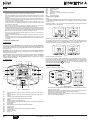
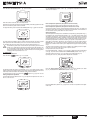
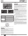
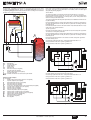
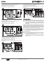
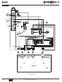
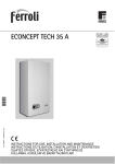
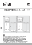
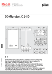
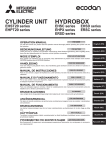
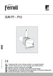
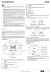
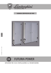
cod. 3540S562 — 01/2011 (Rev. 00)
6
ECONCEPT 51 A
IT - ISTRUZIONE PER L’USO L'INSTALLAZIONE E LA MANUTENZIONE
ES - INSTRUCCIONES DE USO, INSTALACIÓN Y MANTENIMIENTO
TR - KULLANMA, KURULUM VE BAKøM TALIMATLARø
EN - INSTRUCTIONS FOR USE, INSTALLATION AND MAINTENANCE
FR - INSTRUCTIONS D'UTILISATION, D'INSTALLATION ET D'ENTRETIEN
RO - INSTRUCğIUNI DE UTILIZARE, INSTALARE ùI ÎNTRETINERE
RU - ɊɍɄɈȼɈȾɋɌȼɈ ɉɈ ɗɄɋɉɅɍȺɌȺɐɂɂ, ɆɈɇɌȺɀɍ ɂ ɌȿɏɈȻɋɅɍɀɂȼȺɇɂɘ
UK - ȱɇɋɌɊɍɄɐȱə Ɂ ȿɄɋɉɅɍȺɌȺɐȱȲ, ɆɈɇɌȺɀɍ ɌȺ ɈȻɋɅɍȽɈȼɍȼȺɇɇə
ECONCEPT 51 A
Indication during operation
Heating
A heating demand (generated by the Room Thermostat or Remote Timer Control or 010 Vdc signal) is indicated by activation of the circulating pump and the radiator (details
13 and 21 - fig. 1).
|| ||||
The display (detail 11 - fig. 1) shows the actual heating delivery temperature, and during
DHW standby time, the message "d".
|||||
|||| ||
1. GENERAL INSTRUCTIONS
•
Carefully read the instructions contained in this instruction booklet.
•
After boiler installation, inform the user regarding its operation and give him this manual,
which is an integral and essential part of the product and must be kept with care for future
reference.
•
Installation and maintenance must be carried out by professionally qualified personnel,
according to current regulations and the manufacturer's instructions. Do not carry out
any operation on the sealed control parts.
•
Incorrect installation or inadequate maintenance can result in damage or injury. The
Manufacturer declines any liability for damage due to errors in installation and use or failure to follow the instructions.
•
Before carrying out any cleaning or maintenance operation, disconnect the unit from the
power supply using the system switch and/or the special cut-off devices.
•
In case of a fault and/or poor operation, deactivate the unit and do not attempt to repair
it or directly intervene. Contact professionally qualified personnel. Repair/replacement of
the products must only be carried out by professionally qualified using original spare
parts. Failure to comply with the above could affect the safety of the unit.
•
This unit must only be used for its intended purpose. Any other use is considered improper and therefore dangerous.
•
The packing materials are potentially hazardous and must not be left within the reach of
children.
•
The images given in this manual are a simplified representation of the product. In this
representation there may be slight and insignificant differences with respect to the product supplied.
Appears on connecting the Remote Timer Control (optional)
Information symbol
Arrow symbol
Fault
Circulating pump On
Appears on connecting the external probe (optional)
Boiler Off
Fault reset request
16 =
17 =
18 =
20 =
21 =
22 =
23 =
25 =
||| |||
EN
reset
eco
comfort
reset
eco
comfort
fig. 2
DHW circuit (with optional hot water tank installed)
A hot water tank heating demand is indicated by activation of the circulating pump and
the tap (details 9 and 21 - fig. 1). The display (detail 11 - fig. 1) shows the actual hot water
tank sensor temperature, and during heating standby time, the message "d“.
2. OPERATING INSTRUCTIONS
2.1 Introduction
Dear Customer,
|| ||||
||| |||
ECONCEPT 51 A is a high efficiency, low emissions sealed chamber premix condensing heat generator for heating, running on natural gas or LPG and equipped with a microprocessor control system.
The boiler shell consists of an aluminium finned tube exchanger and a ceramic premix
burner, equipped with electronic ignition and ionisation flame control, a modulating
speed fan and a modulating gas valve. ECONCEPT 51 A is a heat generator arranged
to operate alone or in cascade.
2.2 Control panel
16 17 18
20 23
5
|||||
|||| ||
Thank you for choosing a ECONCEPT 51 A wall-mounted boiler featuring FERROLIadvanced design, cutting-edge technology, high reliability and quality construction. Please
read this manual carefully since it provides important information on safe installation, use
and maintenance.
reset
eco
comfort
reset
eco
comfort
fig. 3 Exclude hot water tank (economy)
Hot water tank temperature maintaining/heating can be excluded by the user. If excluded, domestic hot water will not be delivered. The hot water tank can be deactivated by
the user (ECO mode) by pressing the button eco comfort (detail 7 - fig. 1). In ECO mode
the display activates the symbol
(detail 12 - fig. 1). To activate COMFORT mode,
press the button eco comfort (detail 7 - fig. 1) again.
2.3 Lighting and turning off
22
11
Boiler lighting
Press the On/Off button (detail 14 fig. 1).
2
4
A
21
3
13
reset
eco
comfort
10
1
9
12
15
25
reset
eco
comfort
reset
eco
comfort
reset
eco
comfort
B
fig. 4 - Boiler lighting
6
8
14
7
•
fig. 1 - Control panel
Key
1=
2=
3=
4=
5=
6=
7=
8=
9=
10 =
11 =
12 =
13 =
14 =
15 =
38
•
DHW temperature setting decrease button (with optional hot water tank installed)
DHW temperature setting increase button (with optional hot water tank installed)
Heating system temperature setting decrease button
Heating system temperature setting increase button
Display
Summer/Winter mode selection button
Economy/Comfort mode selection (with optional hot water tank installed) and
unit On/Off button
Reset button
DHW operation (with optional hot water tank installed)
Summer mode
Multifunction
Eco (Economy) mode (with optional hot water tank installed)
Heating mode
Unit On / Off button
Burner On
EN
•
•
For the following 120 seconds the display will show FH which identifies the heating
system air venting cycle.
During the first 10 seconds the display will also show the card software release (A
= Display card software release / B = Controller software release).
Open the gas cock ahead of the boiler.
When the message FH disappears, the boiler is ready to operate automatically in
case of a room thermostat demand.
cod. 3540S562 - 01/2011 (Rev. 00)
ECONCEPT 51 A
Turning the boiler off
DHW temperature adjustment (with optional hot water tank installed)
Press the button eco comfort (detail 7 - fig. 1) for 5 seconds.
Use the DHW buttons (details 1 and 2 - fig. 1) to adjust the temperature from a min. of
10°C to a max. of 65°C.
IIIII
IIIII
IIIII
|||||
|
||||||
|
||| |||
eco
comfort
reset
reset
fig. 5 - Turning the boiler off
eco
comfort
fig. 9
When the boiler is turned off, the PCB is still powered.
Domestic hot water (with optional hot water tank installed) and heating operation are disabled. The antifreeze system remains activated.
To relight the boiler, press the button eco comfort (detail 7 fig. 1) again for 5 seconds.
Room temperature adjustment (with optional room thermostat)
Using the room thermostat, set the temperature required in the rooms.
Room temperature adjustment (with optional remote timer control)
Using the remote timer control, set the temperature desired in the rooms. The boiler unit
will set the system water according to the required room temperature. For information on
the remote timer control, please refer to its user's manual.
Sliding temperature
When the optional external probe is installed the corresponding symbol (detail 22 fig. 1)
is activated on the control panel display (detail 5 - fig. 1). The boiler control system works
with "Sliding Temperature". In this mode, the heating system temperature is controlled
according to the outside weather conditions in order to ensure high comfort and energy
saving throughout the year. In particular, as the outside temperature increases, the system delivery temperature is decreased according to a specific "compensation curve".
eco
comfort
reset
fig. 6
The boiler will be immediately ready to operate whenever domestic hot water is drawn
(with optional hot water tank installed) or in case of a room thermostat demand.
To completely disconnect the power to the unit, press the button detail 14 fig. 1.
B
The antifreeze system does not work when the power and/or gas to the unit are
turned off. To avoid damage caused by freezing during long idle periods in winter, it is advisable to drain all water from the boiler, DHW circuit and system; or
drain just the DHW circuit and add a suitable antifreeze to the heating system,
complying with that prescribed in sec. 3.3.
2.4 Adjustments
With Sliding Temperature adjustment, the temperature set with the heating buttons
(details3 and 4 - fig. 1) becomes the maximum system delivery temperature. It is advisable to set a maximum value to allow system adjustment throughout its useful operating
range.
The boiler must be adjusted at the time of installation by qualified personnel. Adjustments can in any case be made by the user to improve comfort .
Compensation curve and curve offset
Press the reset buttonfig. 1 (detail 8 - ) for 5 seconds, to display the actual compensation
curve (fig. 10) which can be modified with the DHW buttons (details 1 and 2 - fig. 1).
Summer/Winter Switchover
Adjust the required curve from 1 to 10 according to the characteristic (fig. 12).
Press the button
By setting the curve to 0, sliding temperature adjustment is disabled.
detail 6 - fig. 1 for 1 second.
II
II
III
IIIIIIIIIII
IIII
IIIII III
I
reset
eco
comfort
reset
eco
comfort
fig. 7
fig. 10 - Compensation curve
The display activates the Summer symbol detail 10 - fig. 1. The heating function is deactivated, whereas the possible production of domestic hot water (with optional external hot
water tank) remains activated. The antifreeze system remains activated.
Press the heating buttons (details 3 and 4 - fig. 1) to access parallel curve offset
(fig. 13), modifiable with the DHW buttons (details 1 and 2 - fig. 1).
(detail 6 - fig. 1) again for 1 second.
Heating temperature adjustment
III
III
Use the heating buttons (details 3 and 4 - fig. 1) to adjust the temperature from a min. of
20°C to a max. of 90°C.
II
II
IIIII IIIII
III
To deactivate Summer mode, press the button
IIIIIIIIIII
reset
IIIII
fig. 11 - Curve parallel offset
IIIII
IIIII
III
IIIIIII
III
IIIIII
reset
eco
comfort
Press the reset button (detail 8 - fig. 1) again for 5 seconds to exit parallel curve adjustment mode.
eco
comfort
fig. 8
cod. 3540S562 - 01/2011 (Rev. 00)
EN
39
ECONCEPT 51 A
If the room temperature is lower than the required value, it is advisable to set a higher
order curve and vice versa. Proceed by increasing or decreasing in steps of one and
check the result in the room.
90
85
80
10
9
8
7
6
The combustion circuit is sealed with respect to the place of installation and therefore the
unit can be installed in any room. However, the place of installation must be sufficiently
ventilated to prevent the creation of any dangerous conditions in case of even small gas
leaks. This safety precaution is required by EEC Directive no. 90/396 for all gas-fired
units, including those with a so-called sealed chamber.
4
3
60
The unit can also work with air drawn from the installation room (B type). In this case, the
room must be provided with adequate ventilation, according to current regulations.
2
50
1
40
Therefore the place of installation must be free of dust, flammable materials or objects
or corrosive gases. The room must be dry and not subject to freezing.
30
The boiler is arranged for wall installation. Wall fixing must ensure a stable and effective
support for the generator.
20
20
10
0
-10
-20
If the unit is enclosed in a cabinet or mounted alongside, a space must be pro-
A vided for removing the casing and for normal maintenance operations
fig. 12 - Compensation curves
OFFSET = 20
10
9
8
90
85
80
7
6
5
70
10
0
-10
7
6
5
4
3
2
1
40
1
30
8
50
2
40
9
60
3
50
10
70
4
60
20
3.3 Plumbing connections
OFFSET = 40
90
85
80
20
The installation instructions given in the following paragraphs concern both single units
and connection in cascade.
3.2 Place of installation
5
70
in the unit, the protection devices cause the unit to switch off or shut down, preventing it
from working.
30
20
-20
20
10
0
-10
-20
fig. 13 - Example of compensation parallel curve offset
If the Remote Timer Control (optional) is connected to the boiler, the above ad-
The heating capacity of the unit must be previously established by calculating the building's heat requirement according to the current regulations. The system must be provided with all the components for correct and regular operation. In particular, provide for all
the protection and safety devices required by the current regulations for the complete
modular generator. They must be installed on the hot water circuit delivery piping, immediately after the last module, within a distance not more than 0.5 metres, with no shutoff
devices in between. The unit is not supplied with an expansion tank; its connection must
therefore be carried out by the Installer.
B
A justments are managed according to that given in table 1.
The safety valve outlet must be connected to a funnel or collection pipe to prevent water spurting onto the floor in case of overpressure in the heating circuit.
Otherwise, if the discharge valve cuts in and floods the room, the boiler manufacturer cannot be held liable.
Do not use the water system pipes to earth electrical appliances.
Before installation, carefully wash all the pipes of the system to remove any residuals or
impurities that could affect proper operation of the unit.
Table. 1
Heating temperature adjustment Adjustment can be made from the Remote Timer Control menu and the boiler
control panel.
B
Also, a filter must be installed on the system return piping to prevent impurities
or sludge from the system clogging and damaging the heat generators.
The filter must be installed when replacing generators in existing systems. The
manufacturer declines any liability for damage caused to the generator by failure to install or inadequate installation of this filter.
DHW temperature adjustment
(with optional hot water tank
installed)
Adjustment can be made from the Remote Timer Control menu and the boiler
control panel.
Summer/Winter Switchover
Summer mode has priority over a possible Remote Timer Control heating
demand.
Carry out the relevant connections according to the diagram in fig. 33 and the symbols
given on the unit.
Eco/Comfort selection (with
optional hot water tank installed)
On disabling DHW from the Remote Timer Control menu, the boiler selects the
Economy mode. In this condition, the button fig. 1detail 7 - on the boiler panel is
disabled.
System water charcteristics
On enabling DHW from the Remote Timer Control menu, the boiler selects the
Comfort mode. In this condition it is possible select one of the two modes with
the button detail 7 -fig. 1.
Both the Remote Timer Control and the boiler card manage Sliding Temperature adjustment: of the two, the Sliding Temperature of the boiler card has priority.
Sliding Temperature
Plumbing system pressure adjustment
The filling pressure with the system cold must be approx. 1.0 bar. If the system pressure
falls to values below minimum, the boiler card will activate fault F37 (fig. 14).
III I I
IIIII
IIIIIIIIIIIIIII
III
IIIIIII
IIIIII
III IIIII
Antifreeze system, antifreeze fluids, additives and inhibitors
The boiler is equipped with an antifreeze system that turns on the boiler in heating mode
when the system delivery water temperature falls under 6°C. The device will not come
on if the electricity and/or gas supply to the unit are cut off. If it becomes necessary, it is
permissible to use antifreeze fluid, additives and inhibitors only if the manufacturer of
these fluids or additives guarantees they are suitable for this use and cause no damage
to the heat exchanger or other components and/or materials of the boiler unit and system. It is prohibited to use generic antifreeze fluid, additives or inhibitors that are not expressly suited for use in heating systems and compatible with the materials of the boiler
unit and system.
III
III
I I II
I I I I I I I I I I I I II I I
reset
III
III
I I I I I I I I I I III
II III
III
I II
In the presence of water harder than 25° Fr (1°F = 10ppm CaCO3), the use of suitably
treated water is advisable in order to avoid possible scaling in the boiler. The treatment
must not in any case reduce the hardness to values below 15°F (Decree 236/88 for uses
of water intended for human consumption). Water treatment is indispensable in the case
of very large systems or with frequent replenishing of water in the system. If partial or
total emptying of the system becomes necessary in these cases, it is advisable to refill it
with treated water.
eco
comfort
III
fig. 14 - Low system pressure fault
Once the system pressure is restored, the boiler will activate the 120-second
A air
venting cycle indicated on the display by FH.
3. INSTALLATION
3.1 General Instructions
THE BOILER MUST ONLY BE INSTALLED BY QUALIFIED PERSONNEL, IN COMPLIANCE WITH ALL THE INSTRUCTIONS GIVEN IN THIS TECHNICAL MANUAL, THE
PROVISIONS OF CURRENT LAW, THE NATIONAL AND LOCAL REGULATIONS,
AND THE RULES OF PROPER WORKMANSHIP.
ECONCEPT 51 A is a high-efficiency heat generator arranged to operate alone or in cascade (bank). When two or more generators ECONCEPT 51 A are installed in cascade
with the original kits FERROLI, respecting the prescriptions of this manual, they can be
considered as a single heat generator of total power equal to the sum of the powers of
all the units connected in cascade.
All the requirements of the current standards and regulations applicable to this “equivalent” generator with total heating capacity must be met. In particular the place of installation, safety devices and fume exhaust system must be adequate for the total heating
capacity of the bank of units.
In fact, each ECONCEPT 51 A is a complete and independent heat generator, equipped
with its own safety devices. In case of overtemperature, a lack of water or no circulation
40
EN
cod. 3540S562 - 01/2011 (Rev. 00)
ECONCEPT 51 A
Hot water tank connection (Optional kit -)
Parameters
The optional kit - is available for connection to an external hot water tank. The kit, which
comprises a circulating pump (ref. 130 - fig. 15), hot water tank probe (ref. S - fig. 15)
and plumbing fittings, must be installed inside the boiler according to the instructions
provided. Then connect to the fittings in the boiler.
Each system requires a different parametrisation. Follow the procedure for accessing the
two menus, given below; for the parameters to be modified, refer to the tables given
alongside the plumbing diagrams.
"Service Menu"
The card Service Menu is accessed by pressing the Reset button for 10 seconds.
Press the Heating buttons to select "tS", "In", "Hi" or "rE"”. “tS” means Transparent Parameters Menu, “In” Information Menu, “Hi” History Menu, and “rE” History Menu Reset.
Select "tS" and press the Reset button.
The card is equipped with 29 transparent parameters also modifiable from Remote Control (Service Menu).
Press the Heating buttons to scroll the list of parameters in increasing or decreasing order. Press the DHW buttons to modify the value of a parameter: the change will be automatically saved.
Press the Reset button to return to the Service Menu. Press the Reset button for 10 seconds to exit to the card Service Menu.
"System Type Menu"
Press the Summer/Winter button for 10 seconds to access the card System Type Menu.
The card has 21 transparent parameters.
Press the Heating buttons to scroll the list of parameters in increasing or decreasing order. Press the DHW buttons to modify the value of a parameter: the change will be automatically saved.
S
Press the Summer/Winter button for 10 seconds to exit the card System Type Menu.
130
One direct heating circuit
10
B
I
210
Check/Change parameter P02 of the "Transparent Parameters Menu" to 1.
Change parameter P.02 of the "System Type Menu" to 1.
11
Change parameter P.09 of the "System Type Menu" to 1.
179
138
10
72/139
209
I*
fig. 15 - Hot water tank connection kit
209
210
10
11
130
179
B
I
S
DHW delivery
Hot water tank return
System delivery
System return
DHW pump kit
Non-return valves (not supplied)
Hot water tank (not supplied)
ISPESL safety devices (not supplied)
Hot water tank probe
A
Outlined connections to be carried out by the installer.
298
D
306
A
fig. 16
One direct heating circuit and one DHW circuit with pump
Check/Change parameter P02 of the "Transparent Parameters Menu" to 2.
Change parameter P.02 of the "System Type Menu" to 1.
Plumbing circuit examples
Key of examples
I*
ISPESL safety devices (When required - not supplied)
D
Hydraulic separator (not supplied)
42
DHW temperature sensor (not supplied)
72
Room thermostat (not supplied)
72b
Room thermostat (not supplied)
95
3-way valve - with spring return: at rest on DHW side (not supplied)
130
Hot water tank circulating pump (not supplied)
138
External probe (not supplied)
139
Remote control (not supplied)
298
Cascade temperature sensor (not supplied)
306
Heating system circulating pump (not supplied)
307
Heating system second circulating pump (not supplied)
SM
Delivery probe (supplied with kit FZ4)
TS
Safety thermostat (not supplied)
PZ
Zone pump (not supplied)
FZ4
Zone regulator
Change parameter P.09 of the "System Type Menu" to 1.
138
72/139
42
I*
130
298
D
306
B
fig. 17
cod. 3540S562 - 01/2011 (Rev. 00)
EN
41
ECONCEPT 51 A
One direct heating circuit and one DHW circuit with diverter valve
Two mixed heating circuits, one direct heating circuit and one DHW circuit with pump
Check/Change parameter P02 of the "Transparent Parameters Menu" to 3.
Check/Change parameter P02 of the "Transparent Parameters Menu" to 2.
Change parameter P.02 of the "System Type Menu" to 1.
Change parameter P.02 of the "System Type Menu" to 1.
Change parameter P.09 of the "System Type Menu" to 1.
Change parameter P.09 of the "System Type Menu" to 1.
Change parameter P.11 of the "System Type Menu" to 1.
For the electrical connection and the zone system settings, refer to the "FZ4 zone regulator" handbook
FZ4
138
72/139
72/139
138
72/139
Zona 1
Zona 2
72/139
Zona 3
42
TS
42
TS
I*
PZ
I*
PZ
SM
M
PR
130
SM
M
298
D
298
D
306
95
F
fig. 21
C
fig. 18
3.4 Electrical connections
Connection to the electrical grid
B
Two direct heating circuits
Check/Change parameter P02 of the "Transparent Parameters Menu" to 1.
Change parameter P.01 of the "System Type Menu" to 4.
Change parameter P.02 of the "System Type Menu" to 1.
Change parameter P.09 of the "System Type Menu" to 1.
The boiler is prewired and provided with a Y-cable and plug for connection to the electricity line. The connections to the grid must be made with a permanent connection and
equipped with a bipolar switch whose contacts have a minimum opening of at least 3
mm, interposing fuses of max. 3A between the boiler and the line. It is important to respect the polarities (LINE: brown wire / NEUTRAL: blue wire / EARTH: yellow-green
wire) in making connections to the electrical line. During installation or when changing
the power cable, the earth wire must be left 2 cm longer than the others.
138
72b
72/139
The unit's electrical safety is only guaranteed when correctly connected to an
efficient earthing system executed according to current safety standards. Have
the efficiency and suitability of the earthing system checked by professionally
qualified personnel. The manufacturer is not responsible for any damage
caused by failure to earth the system. Also make sure that the electrical system
is adequate for the maximum power absorbed by the unit, as specified on the
boiler dataplate.
B
The user must never change the unit's power cable. If the cable gets damaged,
switch off the unit and have it changed solely by professionally qualified personnel. If changing the electric power cable, use solely “HAR H05 VV-F” 3x0.75
mm2 cable with a maximum outside diameter of 8 mm.
I*
Room thermostat (optional)
307
B
306
298
D
D
CAUTION: The room thermostat must have clean contacts. CONNECTING
230 V. TO THE TERMINALS OF THE ROOM THERMOSTAT WILL IRREPARABLY DAMAGE THE ELECTRONIC CARD.
When connecting a remote timer control or a timer switch, do not take the power supply for these devices from their cut-out contacts. Their power supply must
be taken with a direct connection from the mains or with batteries, depending
on the kind of device.
fig. 19
Two mixed heating circuits and one direct heating circuit
Check/Change parameter P02 of the "Transparent Parameters Menu" to 1.
Change parameter P.02 of the "System Type Menu" to 1.
Change parameter P.09 of the "System Type Menu" to 1.
For the electrical connection and the zone system settings, refer to the "FZ4 zone regulator" handbook
FZ4
72/139
138
72/139
Zona 1
72/139
Zona 2
TS
Zona 3
TS
I*
PR
PZ
PZ
SM
M
SM
M
298
D
E
fig. 20
42
EN
cod. 3540S562 - 01/2011 (Rev. 00)
ECONCEPT 51 A
Accessing the electrical terminal block
For connection in cascade (max. 6 modules)
The electrical terminal block is located inside a sealed box at the bottom left of the cabinet. Make the electrical connections as shown in the wiring diagram on fig. 37 and run
the cables through the special cable glands.
1.
Connect the modules as shown in fig. 23 (example with 4 modules)
A
25 26 27 28 29 30 31 32
B
C
25 26 27 28 29 30 31 32
D
25 26 27 28 29 30 31 32
25 26 27 28 29 30 31 32
2
fig. 23 - Connection in cascade
A
B
C
D
1
4
5
6
7
8
9
10 11 12
A
(
((
300
B
306
25 26 27 28 29 30 31 32
4.
5.
C
(
301
130/307
302
256
95
13 14
2.
3.
15 16
17 18 19 20 21 22 23 24
1st Module
2nd Module
3rd Module
4th Module
Carry out all the electrical connections (terminals 4 to 24) on module no. 1
On the remaining modules, only connect the power supply and possible contacts
for: burner lit (300), fault contact (301) and remote reset input (302).
Switch on the power to the entire cascade
After the "FH" procedure, check the correct operation of the cascade:
•
•
•
•
Module 1: arrow symbol at top left of the display
Module 2: arrow symbol at bottom right of the display
Module 3: arrow symbol at bottom right of the display
Module 4: arrow symbol at top right of the display
If this does not occur, disconnect the power and check the wiring in fig. 23.
Settings
All adjustments must be made on all the modules.
Possible faults
If the electrical connection of a module is disconnected for any reason, module 1 will activate fault F70.
72
138
299
298
72B
42
If the electrical connection of a module is disconnected for any reason, the next module
will activate fault F71.
139
3.5 Fume ducts
fig. 22 - Electrical terminal block
42
72
72b
95
The unit is a "C type" with sealed chamber and forced draught, the air inlet and fume outlet must be connected to one of the following extraction/suction systems. The unit is approved to operate with all the Cxy and Bxy flue configurations given on the dataplate
(some configurations are given by way of example in this section). Some configurations
may be expressly limited or not permitted by law, standards or local regulations. Before
proceeding with installation, check and carefully observe the above-mentioned prescriptions. Also, comply with the provisions on the positioning of wall and/or roof terminals and
the minimum distances from windows, walls, ventilation openings, etc.
DHW temperature sensor (not supplied)
Room thermostat (not supplied)
Room thermostat (not supplied)
Diverter valve (not supplied)
A = Heating phase
B = DHW phase
C = Neutral
130
138
139
256
298
299
300
301
302
306
307
NOTE: For valves with 2 wires and spring return, use the connections B and C
DHW circulating pump (not supplied)
External probe (not supplied)
Remote timer control (not supplied)
Modulating heating circulating pump signal
Cascade temperature sensor (not supplied)
Input 0 -10 Vdc
Burner lit contact (voltage-free contact)
Fault contact (voltage-free contact)
Remote reset input (230 Volt)
Heating system circulating pump (not supplied)
Heating system second circulating pump (not supplied)
B
This C-type unit must be installed using the inlet and fume outlet ducts supplied
by the manufacturer in accordance with UNI-CIG 7129/92. Failure to use them
automatically invalidates every warranty and relieves the manufacturer of any
liability.
For fume exhaust pipes longer than 1 metre, during installation take in account
A the natural expansion of the materials when the boiler is operating.
To prevent deformations, leave an expansion space of approx. 2 ÷ 4 mm for every metre
of pipe.
2 ÷ 4 mm
fig. 24 - Expansion
cod. 3540S562 - 01/2011 (Rev. 00)
EN
43
ECONCEPT 51 A
Connection with coaxial pipes
Table. 4 - Accessories
Losses in meq
Ø 80
C13
C33
C33
C33
C13
1.0
BEND 45° M/F
1KWMA65W
1.2
90° M/F
For coaxial connection, fit the unit with one of the following starting accessories. For the
wall hole dimensions, refer to fig. 33. Any horizontal sections of the fume exhaust must
be kept sloping slightly towards the boiler, to prevent possible condensate from flowing
back towards the outside and causing dripping.
Ø80
Ø60
fumes, wall with antiwind
Fume exhaust
Horizontal
2.0
1.8
1KWMA01W
1.5
2.0
1KWMA70W
0.3
0.3
1KWMA85A
2.0
-
1KWMA86A
-
5.0
3.6 Condensate drain connection
The boiler is equipped with an internal trap C for condensate draining.
Fit the inspection union A on the trap, also fitting seal B. Press the flexible tube D on
about 3 cm and secure it with a clamp.
Ø125
Ø100
1000
TERMINAL air, wall
= Fumes)
1.6
1KWMA83W
C13
= Air /
Vertical
PIPE 1 m M/F
PIPE SECTION with test point
fig. 25 - Examples of connection with coaxial pipes (
Air
inlet
Fill the trap with approx. 0.5 l. of water and connect the flexible tube to the drainage system.
136
2.
3.
Fit the inspection union A on the trap, also fitting seal B. Press the flexible tube D
on about 3 cm and secure it with a clamp.
Fill the trap with approx. 0.5 l. of water.
Connect the flexible tube to the drainage system.
30
Ø100
29
Ø60
107
75
159
124
1.
Ø80
Ø80
A
B
Ø80
C
fig. 26 - Starting accessory for coaxial ducts
C
A - Kit 60/100 - 1KWMR53A
B - Kit 60/100 - 1KWMA71W
C - Kit 80/125 - 1KWMA74Y
B
A
D
Before carrying out installation, check with table 2 that the maximum permissible length
is not exceeded, taking into account that every coaxial bend gives rise to the reduction
indicated in the table. For example, a Ø 80/125 duct comprising a 90° bend + 1 horizontal
metre has a total equivalent length of 1.5 metres.
1
2
3
fig. 28 - Condensate drain connection
4. SERVICE AND MAINTENANCE
Table. 2 - Max. length coaxial ducts
Coaxial 60/100
Coaxial 80/125
Max. permissible length
2m
12 m
Reduction factor 90° bend
1m
0.5 m
Reduction factor 45° bend
0.5 m
0.25 m
All adjustment, conversion, commissioning and maintenance operations described below must only be carried out by Qualified Personnel (meeting the professional technical
requirements prescribed by current regulations) such as those of the Local After-Sales
Technical Service.
FERROLI declines any liability for damage and/or injury caused by unqualified and unauthorised persons tampering with the unit.
4.1 Adjustments
Gas conversion
The unit can operate on Natural Gas or LPG and is factory-set for use with one of these
two gases, as clearly shown on the packing and on the dataplate. Whenever a different
gas to that for which the unit is arranged has to be used, a conversion kit will be required,
proceeding as follows:
Connection with separate pipes
1.
2.
3.
4.
C53
C33
C53
fig. 27 - Examples of connection with separate pipes (
B23
•
•
C13
= Air /
•
= Fumes)
Separate Ø80 ducts can be connected directly to the unit.
Before proceeding with installation make sure the maximum permissible length has not
been exceeded, by means of a simple calculation:
1.
2.
3.
Completely establish the layout of the system of split flues, including accessories
and outlet terminals.
Consult the table 4 and identify the losses in meq (equivalent metres) of every component, according to the installation position.
Check that the sum total of losses is less than or equal to the maximum permissible
length in table 3.
Loosen the gas valve fixing ring "A".
Remove the seal "E" and replace gas nozzle "D" with the one contained in the conversion kit.
Refit the parts and check the tightness.
Modify the parameter on the control system.
•
•
5.
6.
put the boiler in standby mode
press the DHW buttons (details 1 and 2 - fig. 1) for 10 seconds: the display
shows "P01" flashing.
Press the DHW buttons (details 1 and 2 - fig. 1) to set parameter 00 (for natural
gas operation) or 01 (for LPG operation).
press the DHW buttons (details 1 and 2 - fig. 1) for 10 seconds.
the boiler will return to standby mode
Apply the label, contained in the conversion kit, near the dataplate.
Using a combustion analyser connected to the boiler fume outlet, make sure the
CO2 content in the fumes, with the boiler operating at max. and min. output, complies with that given in the technical data table for the corresponding type of gas.
A
Table. 3 - Max. length separate ducts
E
Separate ducts
D
20 meq
Max. permissible length
fig. 29 - Gas conversion
44
EN
cod. 3540S562 - 01/2011 (Rev. 00)
ECONCEPT 51 A
TEST mode activation
Press the heating buttons (details 3 and 4 - fig. 1) at the same time for 5 seconds to activate the TEST mode. The boiler lights at the maximum heating power set as described
in the following section.
The heating symbol (detail 13 - fig. 1) and DHW symbol (detail 9 - fig. 1) flash on the display; the heating power will be displayed alongside.
solvents.
Opening the casing
To open the boiler casing (fig. 31):
1.
2.
3.
Undo the screws (1)
Lift the casing (2)
Turn and remove the casing (3)
II
IIIIIII
II
IIIIIII
IIIIIII
IIII
IIIIIIII
boiler casing, panel and aesthetic parts can be cleaned with a soft damp
A The
cloth, possibly soaked in soapy water. Do not use any abrasive detergents and
IIIIIII
reset
2
eco
comfort
fig. 30 - TEST mode (heating power = 100%)
To deactivate the TEST mode, repeat the activation sequence.
The TEST mode is automatically disabled in any case after 15 minutes.
3
Heating power adjustment
To adjust the heating power, switch the boiler to TEST mode (see sec. 4.1).
Press the heating buttons (details 3 and 4 - fig. 1) to increase or decrease the power
(min. = 00 - max. = 100).
1
Press the reset button (detail 8 - fig. 1) within 5 seconds; the max. power will remain
that just set. Exit the TEST mode (see sec. 4.1).
fig. 31 - Opening the casing
4.2 Start-up
Combustion analysis
B
Combustion can be analysed through the air sampling point (detail 2) and fume sampling point (detail 1) shown in fig. 32.
Checks to be made at first lighting, and after all maintenance operations that
involved disconnection from the systems or an operation on safety devices or
parts of the boiler:
Before lighting the boiler
•
•
•
•
•
•
•
•
•
Open any on-off valves between the boiler and the systems.
Check the tightness of the gas system, proceeding with caution and using a soap
and water solution to detect any leaks in connections.
Check correct prefilling of the expansion tank (ref. sec. 5.4).
Fill the water system and make sure all air contained in the boiler and the system
has been vented, by opening the air vent valve on the boiler and any vent valves on
the system.
Fill the condensate trap and check correct connection of the condensate elimination
system.
Make sure there are no water leaks in the system, DHW circuits, connections or boiler.
Check correct connection of the electrical system and efficiency of the earthing system
Make sure the gas pressure value for heating is that required.
Make sure there are no flammable liquids or materials in the immediate vicinity of
the boiler
To take the measurement, it is necessary to:
1.
2.
3.
4.
5.
Open the air and fume sampling points
Insert the probes
Press the "+" and "-" buttons for 5 seconds to activate the TEST mode
Wait 10 minutes for the boiler to stabilise
Take the measurement
For natural gas the CO2 reading must be between 8.7 and 9%.
For LPG the CO2 reading must be between 9.5 and 10%.
A Analyses made with an unstabilised boiler can cause measurement errors.
2
1
1
2
Checks during operation
•
•
•
•
•
•
•
•
•
•
Turn the unit on as described in sec. 2.3.
Make sure the fuel circuit and water systems are tight.
Check the efficiency of the flue and air-fume ducts while the boiler is working.
Check the correct tightness and functionality of the condensate elimination system
and trap.
Make sure the water is circulating properly between the boiler and the systems.
Make sure the gas valve modulates correctly in the heating and domestic hot water
production phases.
Check proper boiler lighting by doing several tests, turning it on and off with the room
thermostat or remote control.
Using a combustion analyser connected to the boiler fume outlet, check that the
CO2 content in the fumes, with the boiler operating at max. and min. output, corresponds to that given in the technical data table for the corresponding type of gas.
Make sure the fuel consumption indicated on the meter matches that given in the
technical data table on sec. 5.4.
Check the correct programming of the parameters and carry out any necessary customization (compensation curve, power, temperatures, etc.).
4.3 Maintenance
Periodical check
To keep the unit working properly over time, it is necessary to have qualified personnel
make an annual check that includes the following tests:
•
•
•
•
•
•
•
•
•
•
•
•
fig. 32 - Combustion analysis
4.4 Troubleshooting
Diagnostics
The boiler is equipped with an advanced self-diagnosis system. In case of a boiler fault,
the display will flash together with the fault symbol (detail 20 - fig. 1) indicating the fault
code.
There are faults that cause permanent shutdown (marked with the letter “A”): to restore
operation, press the RESET button (detail 8 - fig. 1) for 1 second or RESET on the optional remote timer control if installed; if the boiler fails to start, it is necessary to firstly
eliminate the fault.
Faults marked with the letter “F” cause temporary shutdowns that are automatically reset
as soon as the value returns within the boiler's normal working range.
The control and safety devices (gas valve, flow meter, thermostats, etc.) must function correctly.
The fume extraction circuit must be fully efficient.
The airtight chamber must be sealed
The air-fume end piece and ducts must be free of obstructions and leaks
The condensate evacuation system must be efficient with no leakage or obstructions.
The burner and exchanger must be clean and free of scale. When cleaning, do not
use chemical products or wire brushes.
The electrode must be free of scale and properly positioned.
The gas and water systems must be airtight.
The water pressure in the cold water system must be about 1 bar; otherwise, bring
it to that value.
The circulation pump must not be blocked.
The expansion tank must be filled.
The gas flow and pressure must correspond to that given in the respective tables.
cod. 3540S562 - 01/2011 (Rev. 00)
EN
45
ECONCEPT 51 A
Table of faults
5. TECHNICAL DATA AND CHARACTERISTICS
5.1 Dimensions and connections
Table. 5 - Fault list
195
Possible cause
120
120
195
Cure
F39
External probe fault
A41
Sensor positioning
A42
F42
Heating sensor fault
Heating sensor fault
F50
Cascade temperature
sensor fault
A61
Controller DBM12 fault
A62
No communication between
controller and gas valve
Check the regular gas flow to the boiler
and that the air has been eliminated from
the pipes
Check the wiring of the electrode and that
Ignition/detection electrode fault it is correctly positioned and free of any
deposits
Check the gas valve and replace it if
Faulty gas valve
necessary
Insufficient gas supply pressure Check the gas supply pressure
Trap blocked
Check the trap and clean it if necessary
Electrode fault
Check the ionisation electrode wiring
Card fault
Check the card
Check the correct positioning and
Heating sensor damaged
operation of the heating sensor
No water circulation in the
Check the circulating pump
system
Air in the system
Vent the system
Fault F07 generated 3 times in See fault F07
the last 24 hours
Fault F15 generated for 1 hour
See fault F15
(consecutive)
Ionisation electrode fault
Check the position of the ionisation electrode and replace it if necessary
Flame unstable
Check the burner
Gas valve Offset fault
Check the Offset adjustment at minimum
power
Remove the obstruction from the flue,
air/fume ducts obstructed
fume extraction ducts and air inlet and
terminals
Trap blocked
Check the trap and clean it if necessary
Flue partially obstructed or
Check the efficiency of the flue, fume
insufficient
extraction ducts and outlet terminal
Check the correct positioning and
Fume sensor position
operation of the fume sensor
Sensor damaged
Wiring shorted
Check the wiring or replace the sensor
Wiring disconnected
Sensor damaged
Wiring shorted
Check the wiring or replace the sensor
Wiring disconnected
Sensor damaged
Wiring shorted
Check the wiring or replace the sensor
Wiring disconnected
Sensor damaged
Wiring shorted
Check the wiring or replace the sensor
Wiring disconnected
Sensor damaged
Wiring shorted
Check the wiring or replace the sensor
Wiring disconnected
No 230V power supply
Check the wiring of the 3-pin connector
Tachometric signal interrupted Check the wiring of the 5-pin connector
Fan damaged
Check the fan
Electric mains trouble
Check the electrical system
Electric mains trouble
Check the electrical system
Pressure too low
Fill the system
Water pressure switch damCheck the sensor
aged or not connected
Probe damaged or wiring
Check the wiring or replace the sensor
shorted
Probe disconnected after
Reconnect the external probe or disable
activating the sliding temperature the sliding temperature
Delivery sensor detached from Check the correct positioning and
the pipe
operation of the heating sensor
Sensor damaged
Replace the sensor
Sensor damaged
Replace the sensor
Sensor damaged
Wiring shorted
Check the wiring or replace the sensor
Wiring disconnected
Check the earth connection and replace
Controller DBM12 internal error
the controller if necessary.
Controller not connected
Connect the controller to the gas valve
Valve damaged
Replace the valve
A63
A64
A65
F66
Controller DBM12 fault
Controller DBM12 internal error
120
Fault
Fault
code
No gas
A03
Overtemperature protection
activation
A04
Fume extraction duct safety
device activation
A05
Fan protection activation
A06
No flame after ignition stage
(6 times in 4 minutes)
F07
High fume temperature
F10
Delivery sensor 1 fault
F11
Return sensor fault
F12
DHW sensor fault
F13
Fume sensor fault
F14
Delivery sensor 2 fault
F15
Fan fault
F34
F35
Supply voltage under 170V
Faulty mains frequency
F37
Incorrect system water
pressure
630
720
A02
Flame present signal with
burner off
380
45
270
250
1
3
System delivery - Ø 3/4”
Gas inlet - Ø 3/4”
System return - Ø 3/4”
1=
3=
5=
5.2 General view and main components
191
16
5
81
82
278
22
161
19
186
196
36
114
32
Check the earth connection and replace
the controller if necessary.
7
44 193 145
fig. 34 - General view
EN
5
fig. 33 - Dimensions and connections
10
46
65
50
No burner ignition
166
A01
cod. 3540S562 - 01/2011 (Rev. 00)
11
ECONCEPT 51 A
5.3 Plumbing circuit
5.4 Technical data table
The column on the right gives the abbreviation used on the dataplate.
16
191
161
278
196
Data
Unit
kW
49.8
(Q)
Min. heating capacity
kW
11.2
(Q)
Max. Heat Output in heating (80/60°C)
kW
48.8
(P)
Min. Heat Output in heating (80/60°C)
kW
11.0
(P)
Max. Heat Output in heating (50/30°C)
kW
53.0
Min. Heat Output in heating (50/30°C)
kW
12.0
Efficiency Pmax (80-60°C)
%
98.0
Efficiency Pmin (80-60°C)
%
98.5
Efficiency Pmax (50-30°C)
%
106.4
Efficiency Pmin (50-30°C)
%
107.5
%
109
Efficiency 30%
186
114
36
193
Gas supply pressure G20
mbar
20
Max. gas delivery G20
m3/h
5.27
Min. gas delivery G20
m3/h
1.19
Gas supply pressure G31
mbar
37
Max. gas delivery G31
kg/h
3.9
Min. gas delivery G31
kg/h
0.88
Efficiency class Directive 92/42 EEC
-
NOx emission class
210
154
32
14
44
-
5
(NOx)
Max. working pressure in heating
bar
6
(PMS)
Min. working pressure in heating
bar
0.8
Max. heating temperature
°C
95
litres
2.7
Heating water content
Protection rating
IP
Power supply voltage
10
7
11
Value
Max. heating capacity
X5D
V/Hz
Electrical power input
W
Empty weight
kg
Type of unit
230V/50Hz
190
57
C13-C23-C33-C43-C53-C63-C83-B23-B33
PIN CE
fig. 35 - Plumbing circuit
0461BS0878
5.5 Diagrams
Key fig. 34 and fig. 35 - fig. 37
5
Sealed chamber
7
Gas inlet
10
System delivery
11
System return
14
Safety valve
16
Fan
19
Combustion chamber
22
Burner
32
Heating circulating pump
36
Automatic air vent
44
Gas valve
72
Room thermostat (not supplied)
72b
Second room thermostat (not supplied)
81
Ignition electrode
82
Detection electrode
95
Diverter valve (not supplied)
Circulating pump head / pressure losses
H [m H2O] 8
7
3
6
2
5
A
4
1
3
2
1
0
0
500
1.000
1.500
2.000
2.500
Q [l/h]
fig. 36
A = Heating phase
B = DHW phase
A
1-2-3
C = Neutral
98
114
130
138
139
145
154
155
161
186
191
193
196
210
256
278
298
299
300
301
302
306
307
(tmax)
Boiler pressure losses
Circulating pump speed
NOTE: For valves with 2 wires and spring return, use the connections B and C
Switch
Water pressure switch
DHW circulating pump (not supplied)
External probe (not supplied)
Remote timer control (not supplied)
Pressure gauge
Condensate outlet pipe
Hot water tank temperature probe (not supplied)
Condensing heat exchanger
Return sensor
Fume temperature sensor
Trap
Condensate tray
Hot water tank return
Modulating heating circulating pump signal
Double sensor (Safety + Heating)
Cascade temperature sensor (not supplied)
Input 0-10 Vdc
Burner lit contact (voltage-free contact)
Fault contact (voltage-free contact)
Remote reset input (230 Volt)
Heating system circulating pump (not supplied)
Heating system second circulating pump (not supplied)
cod. 3540S562 - 01/2011 (Rev. 00)
EN
47
ECONCEPT 51 A
5.6 Wiring diagram
82
81
44
DBM12KC
V1
V2
X1
16
32
X3
278
T° T°
306
191
16
98
186
X2
114
FUSE
3.15A
130/307
4
5 6
(
230V
50Hz
L
7
8
9
((
300
10
(
301
A
11 12
B
C
302
N
95
13 14 15 16
17 18 19 20 21 22 23 24
25 26 27 28
29 30 31 32
72
138
299
OUT
GND
298 72B 155
256
X04
fig. 37 - Wiring diagram
48
EN
cod. 3540S562 - 01/2011 (Rev. 00)
1
2
3
6
3
6
DSP12C
5
2
5
X03
4
1
4
1
6
5
6
12
4
5
11
10
4
10
3
3
9
2
2
8
9
1
7
8
2
4
X01
7
1
3
139
X05
IT
Dichiarazione di conformità
Il costruttore: FERROLI S.p.A.
Indirizzo: Via Ritonda 78/a 37047 San Bonifacio VR
dichiara che questo apparecchio è conforme alle seguenti direttive CEE:
•
•
•
•
Direttiva Apparecchi a Gas 90/396
Direttiva Rendimenti 92/42
Direttiva Bassa Tensione 73/23 (modificata dalla 93/68)
Direttiva Compatibilità Elettromagnetica 89/336 (modificata dalla 93/68)
Presidente e Legale rappresentante
Cav. del Lavoro
Dante Ferroli
ES
Declaración de conformidad
El fabricante: FERROLI S.p.A.
Dirección: Via Ritonda 78/a 37047 San Bonifacio (Verona)
declara que este equipo satisface las siguientes directivas CEE:
•
•
•
•
Directiva de Aparatos de Gas 90/396
Directiva de Rendimientos 92/42
Directiva de Baja Tensión 73/23 (modificada por la 93/68)
Directiva de Compatibilidad Electromagnética 89/336 (modificada por la 93/68)
Presidente y representante legal
Caballero del Trabajo
Dante Ferroli
TR
Uygunluk beyani
ømalatçi: FERROLI S.p.A.
Adres: Via Ritonda 78/a 37047 San Bonifacio VR
bu cihazin; asagida yer alan AET(EEC) yönergelerine uygunluk içinde oldugunu beyan etmektedir:
•
•
•
•
90/396 Gazla çalistirilan üniteler için Yönetmelik
92/42 Randiman/Verimlilik Yönetmeligi
Yönerge 73/23, Düsük Voltaj (93/68 nolu direktifle degisiklige ugratildi)
89/336 Elektromanyetik Uygunluk Yönetmeligi (93/68 ile degisiklik yapilmistir)
Baskan ve yasal temsilci
øú. Dep.
Dante Ferroli
EN
Declaration of conformity
Manufacturer: FERROLI S.p.A.
Address: Via Ritonda 78/a 37047 San Bonifacio VR Italy
declares that this unit complies with the following EU directives:
•
•
•
•
Gas Appliance Directive 90/396
Efficiency Directive 92/42
Low Voltage Directive 73/23 (amended by 93/68)
Electromagnetic Compatibility Directive 89/336 (amended by 93/68)
President and Legal Representative
Cav. del Lavoro
Dante Ferroli
FR
Déclaration de conformité
Le constructeur : FERROLI S.p.A.
Adresse: Via Ritonda 78/a 37047 San Bonifacio VR
déclare que cet appareil est conforme aux directives CEE ci-dessous:
•
•
•
•
Directives appareils à gaz 90/396
Directive rendements 92/42
Directive basse tension 73/23 (modifiée 93/68)
Directive Compatibilité Electromagnétique 89/336 (modifiée 93/68)
Président et fondé de pouvoirs
Cav. du travail
Dante Ferroli
RO
DeclaraĠie de conformitate
Producător: FERROLI S.p.A.
Adresă: Via Ritonda 78/a 37047 San Bonifacio VR
declară că acest aparat este în conformitate cu următoarele directive CEE:
•
•
•
•
Directiva Aparate cu Gaz 90/396
Directiva Randament 92/42
Directiva Joasă Tensiune 73/23 (modificată de 93/68)
Directiva Compatibilitate Electromagnetică 89/336 (modificată de 93/68)
Preúedinte úi reprezentant legal
Cavaler al Muncii
Dante Ferroli
RU
Ⱦɟɤɥɚɪɚɰɢɹ ɫɨɨɬɜɟɬɫɬɜɢɹ
ɂɡɝɨɬɨɜɢɬɟɥɶ: FERROLI S.p.A.,
ɚɞɪɟɫ: Via Ritonda 78/a 37047 San Bonifacio VR,
ɡɚɹɜɥɹɟɬ, ɱɬɨ ɧɚɫɬɨɹɳɟɟ ɢɡɞɟɥɢɟ ɫɨɨɬɜɟɬɫɬɜɭɟɬ ɫɥɟɞɭɸɳɢɦ ɞɢɪɟɤɬɢɜɚɦ CEE:
•
•
•
•
Ⱦɢɪɟɤɬɢɜɚ ɩɨ ɝɚɡɨɜɵɦ ɩɪɢɛɨɪɚɦ 90/396
Ⱦɢɪɟɤɬɢɜɚ ɩɨ Ʉ.ɉ.Ⱦ. 92/42
Ⱦɢɪɟɤɬɢɜɚ ɩɨ ɧɢɡɤɨɦɭ ɧɚɩɪɹɠɟɧɢɸ 73/23 (ɫ ɢɡɦɟɧɟɧɢɹɦɢ, ɜɧɟɫɟɧɧɵɦɢ ɞɢɪɟɤɬɢɜɨɣ 93/68)
Ⱦɢɪɟɤɬɢɜɚ ɩɨ ɷɥɟɤɬɪɨɦɚɝɧɢɬɧɨɣ ɫɨɜɦɟɫɬɢɦɨɫɬɢ 89/336 (ɫ ɢɡɦɟɧɟɧɢɹɦɢ, ɜɧɟɫɟɧɧɵɦɢ
ɞɢɪɟɤɬɢɜɨɣ 93/68).
ɉɪɟɡɢɞɟɧɬ ɢ ɭɩɨɥɧɨɦɨɱɟɧɧɵɣ ɩɪɟɞɫɬɚɜɢɬɟɥɶ
Ʉɚɜɚɥɶɟɪɟ ɞɟɥɶ ɥɚɜɨɪɨ (ɩɨɱɟɬɧɵɣ ɬɢɬɭɥ, ɩɪɢɫɭɠɞɚɟɦɵɣ
ɝɨɫɭɞɚɪɫɬɜɨɦ ɡɚ ɡɚɫɥɭɝɢ ɜ ɪɭɤɨɜɨɞɫɬɜɟ ɩɪɨɦɵɲɥɟɧɧɨɫɬɶɸ)
Dante Ferroli
UK
Ⱦɟɤɥɚɪɚɰɿɹ ɩɪɨ ɜɿɞɩɨɜɿɞɧɿɫɬɶ
ȼɢɪɨɛɧɢɤ: ɤɨɦɩɚɧiɹ FERROLI S.p.A.
ɡɚ ɚɞɪɟɫɨɸ: Via Ritonda 78/a 37047 San Bonifacio VR
ɡɚɹɜɥɹɽ, ɳɨ ɰɟɣ ɚɩɚɪɚɬ ɜɿɞɩɨɜɿɞɚɽ ɭɫɿɦ ɧɚɫɬɭɩɧɢɦ Ⱦɢɪɟɤɬɢɜɚɦ ȯɋ:
• Ⱦɢɪɟɤɬɢɜɚ ȯɋ 90/396 (Ⱦɢɪɟɤɬɢɜɚ ɩɪɨ ɡɛɥɢɠɟɧɧɹ ɩɪɚɜɨɜɢɯ ɧɨɪɦ ɤɪɚʀɧ-ɱɥɟɧɿɜ ȯɋ ɞɥɹ ɝɚɡɨ-ɪɨɡɯɿɞɧɢɯ
ɭɫɬɚɧɨɜɨɤ)
• Ⱦɢɪɟɤɬɢɜɚ ȯɋ 92/42 (Ⱦɢɪɟɤɬɢɜɚ ɩɪɨ ɜɢɦɨɝɢ ɄɉȾ ɞɥɹ ɧɨɜɢɯ ɜɨɞɨɝɪɿɣɧɢɯ ɤɨɬɥɿɜ, ɩɪɚɰɸɸɱɢɯ ɧɚ ɪɿɞɢɧɧɨɦɭ
ɿ ɝɚɡɨɩɨɞɿɛɧɨɦɭ ɩɚɥɢɜɿ)
• Ⱦɢɪɟɤɬɢɜɚ ȯɋ 73/23 (Ⱦɢɪɟɤɬɢɜɚ ɩɪɨ ɡɛɥɢɠɟɧɧɹ ɩɪɚɜɨɜɢɯ ɧɨɪɦ ɤɪɚʀɧ-ɱɥɟɧɿɜ ȯɋ, ɳɨ ɫɬɨɫɭɸɬɶɫɹ
ɟɥɟɤɬɪɨɨɛɥɚɞɧɚɧɧɹ, ɹɤɟ ɜɢɤɨɪɢɫɬɨɜɭɽɬɶɫɹ ɜ ɩɟɜɧɢɯ ɦɟɠɚɯ ɧɚɩɪɭɝɢ) (ɡɦɿɧɟɧɚ Ⱦɢɪɟɤɬɢɜɨɸ ȯɋ 93/68)
• Ⱦɢɪɟɤɬɢɜɚ ȯɋ 89/336 (Ⱦɢɪɟɤɬɢɜɚ ɩɪɨ ɩɪɢɜɟɞɟɧɧɹ ɭ ɜɿɞɩɨɜɿɞɧɿɫɬɶ ɡɚɤɨɧɨɞɚɜɫɬɜ ɤɪɚʀɧ-ɱɥɟɧɿɜ ɜ ɨɛɥɚɫɬɿ
ɟɥɟɤɬɪɨɦɚɝɧɿɬɧɨʀ ɫɭɦɿɫɧɨɫɬɿ) (ɡɦɿɧɟɧɚ Ⱦɢɪɟɤɬɢɜɨɸ ȯɋ 93/68).
ɉɪɟɡɢɞɟɧɬ ɿ ɡɚɤɨɧɧɢɣ ɩɪɟɞɫɬɚɜɧɢɤ
Ʉɚɜɚɥɟɪ ɩɪɚɰɿ
Dante Ferroli
FERROLI S.p.A.
Via Ritonda 78/a
37047 San Bonifacio - Verona - ITALY
www.ferroli.it