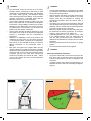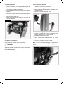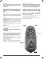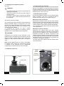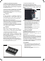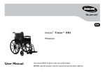
1
Powered Wheelchair Instructions for Use Quickie Tango 034202.UK If you are visually impaired, this document can be viewed in PDF format at www.SunriseMedical.com or alternatively is available on request in large text. For further information on the full specification and options and accessories please refer to the order form. All information is subject to change without notification. Please consult Sunrise Medical with any queries you may have. User Information WARNING! Intended use power wheel chairs: DO NOT USE YOUR WHEELCHAIR UNTIL THIS MANUAL HAS BEEN READ AND UNDERSTOOD. Power wheelchairs are exclusively for a user who is unable to walk or has limited mobility, for their own personal use in- and outdoor. When an Attendant Control Module is fitted, the Power Wheelchair may be operated by an assistant on behalf of the user. When a Dual Control Module is fitted the Power Wheelchair may be operated by the user, or control may be switched to an assistant to operate on behalf of the user. The maximum weight limit (includes both the user and any weight of accessories fitted to the wheelchair) is marked on the serial number label, which is affixed to the chassis of the chair. The chair serial number is affixed also to the front page of the owners manual supplied with the wheelchair. Warranty can only be taken on if the product is used under the specified conditions and for the intended purposes. The intended lifetime of the wheelchair is 5 years. Please DO NOT use or fit any 3rd party components to the wheelchair unless they are officially approved by Sunrise Medical. Area of application The variety of fitting variants as well as the modular design mean that it can be used by those who cannot walk or have limited mobility e.g. because of: • Paralysis • Loss of extremity (leg amputation) • Extremity defect deformity • Joint contractures/joint injuries • Strokes and brain injuries • Neurological disabilities (e.g. MS, Parkinson…) • Illnesses such as heart and circulation deficiencies, disturbance of equilibrium or cachexia as well as for elderly people who still have the strength in the upper body. • Persons who are mentally and physically able to control an input device to operate the chair and its functions in a safe way. When considering provision, please also note the body size, weight including the distribution of body weight, the user’s physical and psychological constitution, the age of the user, their living conditions and their environment. If in doubt a health care professional should be involved to ensure the user is not exposed to unacceptable risks. Sunrise Medical is ISO 9001 certified, which ensures quality at all stages of the development and production of this wheelchair. Sunrise Medical declares under its sole responsibility that this product is in conformity with the requirements of the directive 93/42/EEC amended by 2007/47/EEC.” Sunrise Medical declares that this product fulfils the performance requirements for a “Crash Test” to ISO 7176-19. The Serial Number and other important information may be found on a label situated on the right-hand side, main frame of the product. Back Upholstery Joystick Stabilising Bar Hand control Module Control Lever Height/width adjustable Armrests cushion Battery Box Drive Wheel Motors footrests Castors Due to its modular design, simplicity and wide range of adjustments, the Quickie Tango is a perfect choice for easy service, refurbishment and recycle requirements. As a part of our ongoing product improvement initiative, Sunrise Medical reserves the right to change specifications and design without notice. Further, not all features and options offered are compatible with all configurations of the wheelchair. All dimensions are approximate and may be subject to change. 1.0 Your Wheelchair: 7 7.0 VR2 Control System (Fig.7.1): 2.0 How to use this manual: 7 7.1 On/Off button: ������������������������������������������������������� 26 7.2 Battery Level Indicator: ��������������������������������������� 26 7.3 Locking/unlocking the wheelchair: �������������������� 26 7.4 Operating the control joystick: ��������������������������� 27 7.5 Maximum speed/profile indicator: ���������������������� 27 7.6 The horn button: ��������������������������������������������������� 27 7.7 Speed/Profile decrease button: �������������������������� 27 7.8 Speed/Profile increase button: ��������������������������� 27 7.9 Actuator button and LEDs: ���������������������������������� 27 7.10 VR2-L ������������������������������������������������������������������� 28 7.11 Charging and programming socket: ����������������� 29 7.12 VR2 dual control unit: ���������������������������������������� 29 7.13 Control button and indicator: ���������������������������� 29 7.14 Actuator button and LED: ���������������������������������� 29 7.15 Maximum speed button and indicator: ������������� 30 7.16 Quickie Direct Actuator Control Box: ��������������� 30 7.17 Directional attendant control............................. 30 2.1 Introduction: �����������������������������������������������������������������7 2.2 Guarantee: ��������������������������������������������������������������������7 2.3 Warranty conditions: ����������������������������������������������������7 3.0 Label Explantation / Word definitions: 8 3.1 Definitions of words used in this manual: �����������������8 4.0 Safety: 10 4.1 General Warnings: ������������������������������������������������������10 4.2 Features and options: ������������������������������������������������10 4.3 Preliminary checks: ���������������������������������������������������10 4.4 Emergency braking: ���������������������������������������������������10 4.5 Kerbs, (Fig 4.1): ����������������������������������������������������������10 4.6 Tyres: ���������������������������������������������������������������������������11 4.7 Freewheel device, (Fig.4.2): ���������������������������������������11 4.8 Transportation in vehicles: ����������������������������������������11 4.9 Occupant Restraint Instruction: ��������������������������������12 4.10 Transportability - Positioning of Tie down Restraints on the Wheelchair: ����������������13 4.11 EMC - Radio transmitting devices: �������������������������14 4.12 Sharp turns: ��������������������������������������������������������������15 4.13 Weight limit: ��������������������������������������������������������������15 4.14 Hot surfaces: ������������������������������������������������������������15 4.15 Road caution: �����������������������������������������������������������15 4.16 Adverse conditions: �������������������������������������������������15 4.17 Ramps: ����������������������������������������������������������������������15 4.18 Transfer to and from the chair: �������������������������������15 4.19 Anti tips: ��������������������������������������������������������������������15 4.20 Use on a slope: ���������������������������������������������������������16 4.21 Gradients: ascents: ��������������������������������������������������16 4.22 Gradients: descents: �����������������������������������������������16 4.23 Lap belt: ��������������������������������������������������������������������16 4.24 Rear View Mirror:...................................................... 18 5.0 Assembly: 19 5.1. Footrest (Fig. 5.0-5.1): ����������������������������������������������19 5.2. Armrest (Fig. 5.2): �����������������������������������������������������19 5.3. Anti-tip wheels (Fig.5.3): ������������������������������������������19 5.4. Kerb climber (Fig. 5.4): ���������������������������������������������19 5.5. Batteries (Fig.5.5): ����������������������������������������������������20 5.6. Wheels (Fig.5.6 & 5.7): ���������������������������������������������20 5.7. Fitting The Lap Belt : �������������������������������������������������21 5.8 Crutch Holder, (Fig.5.11): �������������������������������������������21 5.9 Lights and indicators, (Fig.5.12): ������������������������������21 6.0 Using The Wheelchair: 22 6.1 Preparing for stowed transportation: ����������������������22 6.2 To use the wheelchair again: �������������������������������������22 6.3 Mechanical Fixed Reclining back (-3° to 12°): ��������22 6.4 Manual Reclining back with gas strut: ���������������������22 6.5 Powered Reclining back (-3° to 30°) �����������������������22 6.6 Fixed Seat Tilt: ������������������������������������������������������������23 6.7 Manual seat tilt: ����������������������������������������������������������23 6.8 Powered seat tilt: ��������������������������������������������������������23 6.9 Powered Height-adjustable legrests: �����������������������24 6.10 Manual Elevating-Height-adjustable footrests �����24 6.11 Slopes (Fig.6.8): �������������������������������������������������������24 6.12 Transfers (Fig.6.9): ��������������������������������������������������24 6.13 Freewheel device (Fig. 6.6): �������������������������������������25 6.14 Tyre pressure: ����������������������������������������������������������25 6.15 Laterals (Fig.6.11-6.12)����������������������������������������������25 6.16 Mounting a kerb or step (Fig. 6.11): ������������������������25 6.17 Dismounting the kerb (Fig. 6.12): ����������������������������25 26 8.0 Troubleshooting The VR2 Hand Control: 31 9.0 Batteries and Charging: 33 10.0 Adjustments: 38 9.1. Battery & Charger Specification: ����������������������� 33 9.2 Electrical fuses: ��������������������������������������������������� 33 9.3 Batteries (Fig. 9.1 - 9.9): ��������������������������������������� 33 9.4 General battery information: ������������������������������� 35 9.5 Maintenance-free batteries: ��������������������������������� 35 9.6 Battery care: ��������������������������������������������������������� 35 9.7 Maintenance-free battery care plan: ������������������� 35 9.8 General charger information: ������������������������������ 36 9.9 Charger Specification: ���������������������������������������� 36 9.10 Charger safety features: ������������������������������������ 36 9.11 Procedure for connecting the charger and charging: ������������������������������������������������������ 36 9.12 Charger safety and caution notes: ������������������� 36 9.13 The range of your vehicle: ��������������������������������� 37 9.14 Common battery statements: ���������������������������� 37 10.1 Adjustment of the footrest (Fig. 10.1): ������������ 38 10.2 Width Adjustment of the footrests: ������������������ 38 10.3 Adjustment of the armrests: ������������������������������ 38 10.4 Seat depth adjustments: ����������������������������������� 38 10.5 Control Adjustment (Fig. 10.6): ������������������������ 39 10.6 Dual/Attendant control: �������������������������������������� 39 10.7 Parallel swing-away control (Fig.10.7): ������������ 39 10.8 Programming: ���������������������������������������������������� 39 11.0 Cleaning: 40 11.1 Cleaning General: ����������������������������������������������� 40 11.2 Cleaning seating: ������������������������������������������������ 40 11.3 Cleaning control system: ����������������������������������� 40 11.4 Speciality controls: �������������������������������������������� 40 12.0 Shipping & Storage Requirements: 40 12.1 Storage temperature & humidity: �������������������� 40 12.2 Special shipping requirements: ����������������������� 40 12.3 Medium to long term storage: �������������������������� 40 13.0 Disposal: 41 14.0 Specifications: 41 15.0 Guarantee: 42 16.0 Service History: 42 17.0 Performance checks: 43 1.0 Your Wheelchair: 2.0 How to use this manual: We at Sunrise Medical want you to get the best out of your TANGO wheelchair. This Owner’s Manual will familiarise you with the chair and its features. It contains hints on everyday usage and general care in addition to information on the high quality standards which we adhere to and details about the guarantee. 2.1 Introduction: Please keep a note of your local service agent’s address and telephone number in the space below. In the event of a breakdown, contact them and try to give all relevant details so they can help you quickly. The wheelchairs shown and described in this manual may not be exactly the same in every detail as your own model. However, all instructions are still entirely relevant, irrespective of detail differences. Your wheelchair should be delivered fully configured for your use; there are a wide range of components and adjustments available on the Tango. For further information about these you should contact your Sunrise Medical authorised dealer. Your wheelchair will reach you in excellent condition having been personally inspected before leaving our factory. Following the guidelines for maintenance and cleaning your wheelchair will maintain its first class condition and give you complete satisfaction. The Tango has been designed for use by an individual on a daily basis. It is suitable for both indoor and outdoor use (Class B). It is only intended for use as a pavement vehicle, but may also be used when crossing between pavements. This vehicle has been designed for a single occupant of limited mobility up to the weight of 125Kg (dependant on options chosen for your chair) who has the cognitive, physical and visual ability to control the vehicle safely on a maximum slope of 18% (10°). If you are in any doubt as to the suitability of the power chair, contact your local Sunrise Medical approved supplier for clarification, prior to commencing use. It is very important to read the relevant section of the owner’s manual when making any minor adjustments. Consult the Technical Manual or your local Sunrise Medical authorised dealer for more complex adjustments. If you have any queries about the use, maintenance or safety of your wheelchair, please contact your local approved Sunrise Medical service agent. If you do not know of an approved dealer in your area or have any other questions please write or telephone: Sunrise Medical Thorns Road Brierley Hill West Midlands DY5 2LD Phone:0845 605 66 88 Fax: 0845 605 66 89 www.SunriseMedical.com NOTE: The manufacturer reserves the right to alter without notice any weights, measurements or other technical data shown in this manual. All figures, measurements and capacities shown in this manual are approximate and do not constitute specifications. 2.2 Guarantee: The guarantee form is included in the Sunrise Pack. Please fill in the relevant details and return to us to register your entitlement. THIS IN NO WAY AFFECTS YOUR STATUTORY RIGHTS. 2.3 Warranty-Repair-Service conditions: 1) The repair or replacement will be carried out by an authorised Sunrise Medical dealer/service agent. 2) To apply the warranty conditions, should your wheelchair require attention under these arrangements, notify the designated Sunrise Medical service agent immediately giving full information about the nature of the difficulty. Should you be operating the wheelchair away from the locality of the designated Sunrise Medical service agent, work under the “Warranty Conditions” will be carried out by any other service agent designated by the manufacturer. 3) Should any part of the wheelchair require repair or replacement, as a result of a specific manufacturing or material defect, within twenty four months from the date on which the possession of the wheelchair was transferred to the original purchaser, and subject to it remaining within that ownership, the part or parts will be repaired or replaced completely free of charge if returned to the authorised service agent. If you are unsure who your local servicing agent is: Please contact Sunrise Medical using the contact details opposite. Dealer signature and stamp Quickie Tango 7 4) Any repaired or replaced part will benefit from these arrangements for the balance of the warranty period applicable to the wheelchair. 3.0 Label Explantation / Word definitions: 3.1 Definitions of words used in this manual: 5) Parts replaced after the original warranty has expired are covered for a further twelve months. Word Definition 6) Items of a consumable nature will not generally be covered during the normal warranty period, unless such items have clearly suffered undue wear as a direct result of an original manufacturing defect. These items include amongst others upholstery, tyres, inner tubes and similar parts. On powered products this will also include batteries, motor brushes etc DANGER! Advice to the user of Potential Risk of serious injury or death if the advice is not followed WARNING! Advice to the user of a potential risk of injury if the advice is not followed CAUTION! Advice to user that potential damage to equipment may occur if the advice is not followed 7) The above warranty conditions apply to all wheelchair parts for models purchased at full retail price. 8) Under normal circumstances, no responsibility will be accepted where the wheelchair has required repair or replacement as a direct result of: a) The wheelchair or part not having been maintained or serviced in accordance with the manufacturer’s recommendations, as stated in the Owner’s Manual and/or Service Manual. Or failing to use only the specified original equipment parts. b) The wheelchair or part having been damaged by neglect, accident or improper use. NOTE: RWD General advice or best practice Rear Wheel Drive Reference To Additional Documentation c) The wheelchair or part having been altered from the manufacturer’s specifications, or repairs having been attempted prior to the service agent being notified. FREEWHEEL LEVER DECALS Right-Hand decal left-hand decal Fig.3.1 8 Quickie Tango Fig.3.2 WARNING! – Do Not Touch - HOT WARNING! – Danger of finger entrapment The power Tilt modules are factory fitted for optimum stability and for conformance to strict standard requirements. Changing the fitted position of the module can reduce the stability of the product, therefore do not change this setting Battery Label Warning! Instructions and Circuit Diagram ATTACHED TO JOYSTICK Warning! DO NOT DRIVE YOUR WHEELCHAIR ON A SLOPE WITH THE BACKREST RECLINED Fig.3.3 Quickie Tango 9 4.0 Safety: If you follow the instructions given in this manual, you will enjoy many trouble-free years of use: WARNING! • • • This vehicle is not designed for use on the road except for crossing from one kerb to another. Load data always refers to one single person as operator. The wheelchair is authorised for use by one person or one seated person and their attendant if using a Dual or Attendant control unit. WARNINGS! 4.1 General Warnings: • Always ensure that your wheelchair is switched off before attempting to mount or dismount. • Always ensure that you are able to operate all controls from a comfortable position. Paying attention to your posture is essential to ensure your continued comfort and well being. • Always make sure that you can be seen clearly, especially if you intend using your wheelchair in poor light. • This wheelchair has been built to match the needs of a particular user. If used by another user then it may need to be adjusted and reprogrammed. • Do not let children or others use your wheelchair. • Do not lift or hoist the wheelchair by any detachable parts such as leg rests, arm rests etc. CAUTION! 4.2 Features and options: Some of the options shown in this manual may not be available in your country and may also restrict the overall physical limits of the standard product (e.g. max. speed, user weight limit, etc.). Those limitations are marked on the order form, in the technical manual and in this owner’s manual. For further information please consult your Sunrise Medical authorised dealer. DANGER! 4.3 Preliminary checks: • You should not try to manoeuvre at full speed. • If you have to make a sudden turn, slow down first using the joystick or the speed control knob. • This is very important if you are going down a hill. • Lack of attention to this point may result in your overturning the wheelchair. • Always check that the wheelchair is switched off before trying to get in or out. • Always check that you can operate all the controls from a comfortable seated position. It is essential to pay attention to posture in order to assure comfort and well-being. • Always check that the freewheel device is switched off before setting the chair in motion. • Always check that you can be seen clearly, especially if you are using the wheelchair in conditions of low visibility. WARNING! 4.4 Emergency braking: If power is cut by means of the ON/OFF button, braking will be immediate and total. This method of stopping is not recommended except for emergencies, since the stop will be extremely sudden. 4.5 Kerbs, (Fig 4.1): • Always cross the road as rapidly as possible, since other vehicles may appear. • Do not attempt to climb or to descend from, a kerb of more than 100 mm. height. • Do not attempt to ascend high kerbs, steep slopes or cambers due to the risk of falling out of the chair or tipping over. • Do not attempt to ascend any kerb in the vicinity of a drain cover, uneven surfaces, or gravel covering. • Do not attempt to descend a kerb of more than 50 mm in forward position. • Do not attempt to climb or descend any kerb at an oblique angle. Approach only at an angle of 90° with at least 500mm run-up. Fig.4.1 10 Quickie TANGO Tango Ref: P19093 4.6 Tyres: The tyres of a wheelchair suffer wear depending on how much the chair is used. Check them regularly, especially for inflation pressure, according to the service instructions in this manual. 4.8 Transportation in vehicles: This product is suitable to use as a seat in vehicles as per certificate ISO / NP 7176-19: 2001, and using the restraint system Unwin (4 point WWR / ATF / K / R) DANGER! WARNING! NEVER inflate the tyres with the air hose of a service station. WARNING! 4.7 Freewheel device, (Fig.4.2): Also see Fig.3.1 • Only use this function to push the chair manually from one spot to another. • Keep in mind that while the freewheel system is in operation, the chair is without a braking system. • Disengaging the motor causes an error message to appear in the control, which is indicated when the LED display flashes rapidly. • For safety reasons the wheelchair can no longer be moved using the joystick. • Do not operate the freewheel device whilst seated in the wheelchair. • The freewheel device should only be operated by a person who has the strength and agility to be able to fully manoeuvre the wheelchair safely, during freewheel. A wheelchair secured in a vehicle will not provide the equivalent level of safety and security of a vehicle seating system. It is always recommended that the user transfers to the vehicle seating. It is recognised that this is not always practical for the user to be transferred and in these circumstances where the user must be transported whilst in the wheelchair the following advice should be followed: • • • • Fig. 4.2 Confirm that the vehicle is suitably equipped to transport a passenger in a wheelchair, and ensure the method of access/egress is suitable for your wheelchair type. The vehicle should have the floor strength to take the combined weight of the user, the wheel chair and accessories. Sufficient space should be available around the wheelchair to enable clear access to attach, tighten and release the wheelchair and occupant tie down restraints and safety belts. The occupied wheelchair must be located in a forward facing position and secured by the wheelchair tie down and occupant restraint straps (WTORS tie downs) meeting the requirements of ISO 10542 or SAE J2249, in accordance with the WTORS manufacturers’ instructions, (Fig. 4.3). The wheelchair’s use in other positions within a vehicle has not been tested e.g. transportation in a side facing position must not be carried out under any circumstances. (Fig. 4.3). Fig.4.3 Quickie Tango 11 DANGER! • • • • • The wheelchair should be secured by a Tie Down Restraint system, conforming to ISO 10542 or SAE J2249 with non-adjustable front straps and adjustable rear straps, which typically use Karabiner clips/S hooks and tongue and buckle fittings. These restraints generally comprise of 4 individual straps that are attached to each corner of the wheelchair. The tie-down restraints should be fitted to the main frame of the wheelchair as indicated by the diagrams in the section, Transportability Positioning of Tie down Restraints on the Wheelchair, (next page), and not to any attachments or accessories, e.g. not around the spokes of wheels, brakes or footrests. The tie–down restraints should be attached as close as possible at an angle of 45 degrees and tightened securely in accordance with the manufacturer’s instructions. Alterations or substitutions must not be made to the wheelchair tie down points or to structural and frame or components without consulting the manufacturer. Failure to do so will invalidate the ability of a Sunrise Medical wheelchair to be transported within a vehicle. Both pelvic and upper torso restraint belts must be used to restrain the occupant to reduce the possibility of head and chest impacts with the vehicle components and serious risk of injury to the user and other vehicle occupants. (Fig.4.4) The upper torso restraint belt should be mounted to the vehicle “B” pillar - failure to do so will increase the risk of serious abdominal injuries to the user. Fig.4.4 12 Quickie Tango DANGER! • • • • • • • A head restraint suitable for transportation (see label on headrest) must be fitted and suitably positioned at all times during transportation. Postural supports (lap straps, lap belts) should not be used or relied on for occupant restraint in a moving vehicle unless they are labelled as meeting the requirements specified in ISO / NP 7176-19: 2001 or SAE J2249 The safety of the user during transportation depends upon the diligence of the person securing the tie-down restraints and they should have received appropriate instructions and/or training in their use. Wherever possible remove and stow safely away from the wheelchair all auxiliary equipment, for example: Crutches, Loose cushions, Tray Tables, etc. Articulating/elevating leg rest should not be used in the elevated position when the wheelchair and user are being transported and the wheelchair is restrained using Wheelchair Transport and Occupant Restraints. Reclining backrests should be returned to an upright position. The manual brakes must be firmly applied. DANGER! 4.9 Occupant Restraint Instruction: • The pelvic restraint belt must be worn low across the front of the pelvis so that the angle of the pelvic belt is within the preferred zone of 30 to 75 degrees to the horizontal. • A steeper (greater) angle within the preferred zone is desirable i.e.closer to, but never exceeding 75degrees. (Fig.4.5). Fig.4.5 • • • • • • • The upper torso restraint belt must fit over the shoulder and across the chest as illustrated Fig 4.6 and Fig 4.7. Restraint belts must be adjusted as tightly as possible consistent with user comfort. Restraint belt webbing must not be twisted when in use. Restraints should be mounted to the vehicle “B” pillar and should not be held away from the body by wheelchair components such as armrest or wheels, (Fig.4.6). The tie down symbol (Fig.4.8) on the wheelchair frame indicates the position of the wheelchair restraint straps. The straps are then tensioned after the front straps have been fitted to secure the wheelchair. The attachment points to the chair are the brackets on the front side frames, (Fig.4.10) and the brackets on the rear of the frame, (Fig.4.12). The straps are attached to the brackets as shown in Fig.11 for front and Fig.13 for rear. 4.10 Transportability - Positioning of Tie down Restraints on the Wheelchair: The Tie Down Label indicates the position of the fixing points for the tie down restraints on the wheelchair, Fig.4.8 The wheelchair secured with front and rear wheelchair tie down restraints (Fig 4.9). Fig.4.6 Fig.4.9 Position of the Front tie down label and bracket, (Fig.4.10). Fig.4.7 Fig.4.10 Quickie Tango 13 Fig.4.11 Position of the Front tie down restraint., (Fig.4.11). Fig.4.12 Fig.4.13 Position of the Rear tie down restraint, (Fig.4.13). WARNING! 4.11 EMC - Radio transmitting devices: When operating two-way radio, walkie-talkies, C.B., amateur radio, public mobile radio and other powerful transmitting devices the wheelchair should be brought to a halt and turned off. The operation of cordless, mobile telephones and cell phones including hands-free devices is permitted but if abnormal operation of the wheelchair is encountered then the chair must be brought immediately to a halt and turned off. Note: the electrical systems of the wheelchair may disturb the performance of alarm systems in retail shops. Position of the Rear tie down label & bracket, (Fig.4.12). 14 Quickie Tango DANGER! 4.12 Sharp turns: Full speed turns should not be attempted. If you need to turn sharply you must reduce your speed with the joystick or speed setting. This is particularly important when travelling across or down a slope. Disregarding this advice could lead to your wheelchair tipping over. DANGER! 4.13 Weight limit: • The user plus items carried should never exceed a total weight of 125 kgs. • Never use this chair for weight training if the total weight (user plus additional weights) exceed a total weight of 125 kgs. • Exceeding the weight limit is likely to damage the seat, frame or fasteners and may cause severe injury to you or others from chair failure • Exceeding the weight limit will void the warranty Wheelchair motors: 4.14 Hot surfaces: WARNING! After prolonged use, the motors will produce heat, which is radiated through the motors’ outer casing. Do not touch the motors’ outer casing for at least 30 minutes after using the wheelchair, to allow it to cool. WARNING! Not only motors can become hot during the operation of the chair, the upholstery material and armrests may heat up when standing in the sun. DANGER! 4.15 Road caution: • Please show the utmost consideration for the other traffic on the road. • Remember that the last thing a car or lorry driver expects to see is a wheelchair backing off the kerb into the road. • If in any doubt, do not risk crossing the road until you are certain that it is safe. • Always cross the road as quickly as possible; there may be other traffic. WARNING! 4.16 Adverse conditions: Please be aware that when driving your wheelchair in adverse conditions, e.g. on wet grass, mud, ice, snow or other slippery surfaces, you may experience a reduction in the grip and traction of your wheelchair. We recommend you take extra precautions in these conditions, particularly on hills and slopes; your wheelchair could become unstable or skid causing possible injury. Extreme variances in temperature may trigger the self protect mechanism in the control system. If this occurs the control system will temporarily shut down to prevent damage to the electronics or the chair. WARNING! 4.17 Ramps: • When using a ramp, please ensure that it is capable of taking the combined weight of the power chair and yourself. • If a ramp is being used to load a chair into a vehicle, please ensure the ramp is properly secured to the vehicle. • Always approach the ramp head-on and exercise caution. • Please ensure your ramp is suitable for the product you are transporting. WARNING! Maximum ramp angle is 10° (18%) 4.18 Transfer to and from the chair: Sunrise Medical recommend that you consult your healthcare professional for assistance in developing your personal front or side transfer technique to best suit your needs and avoid any personal injury. WARNING! 4.19 Anti tips: • Make sure that anti tips are not damaged or worn before using your chair. • Check the anti tips are functioning correctly on a regular basis. • Attendants must be aware of the location of the anti tips to prevent feet being trapped underneath causing injury. • Attendants - Do not stand on the anti tips, this could cause the wheelchair to become unstable. Quickie Tango 15 WARNING! 4.20 Use on a slope: Your wheelchair has been designed and tested to allow its use on slopes or gradients of up to 10° (18%). • Before attempting to climb or descend a slope or a kerb, caution should be taken when using weight shift options (e.g. powered recline) of the seat and/or your body for a counter balance weight. • To improve stability lean forward when driving uphill, with the seat and back in an upright position. • Alternatively sit in an upright position when travelling in a forward, downhill direction or recline the seat backwards. We strongly recommend that you return back to an upright lowered position before attempting to climb or descend a slope. • Failure to do this may cause the wheelchair to become unstable. • If you are in any doubt about the capabilities of your wheelchair on a slope then do not attempt to drive up or down the slope/kerb; try to find an alternative route. WARNING! 4.23 Lap belt: Before using your wheelchair ensure the Lap belt is worn and correctly adjusted before use. The lap belt is fitted to the wheelchair as shown in the fitting instructions in section 5.7. It is important that the belt is secured around the back of the wheelchair. The straps can be fed between the armrest and backrest. Adjust the belt position so that the buckles are in the centre of the seat. See section 5.7. Adjust the lap belt to suit the user’s needs as follows: To increase the belt length: Feed the belt through slide adjusters and male buckle to provide more belt length, (Fig.4.14). Fig.4.14 WARNING! 4.21 Gradients: ascents: • When going uphill, keep the chair moving. • Steer by moving the joystick from side to side. • If you have stopped on a hill, you should start slowly. • On a RWD chair, if necessary lean forward to prevent the tendency for the front wheels to lift. WARNING! 4.22 Gradients: descents: • On descents, it is important not to let the wheelchair accelerate beyond its normal level of ground speed. • It is safer to proceed slowly down steep descents (below the speed of 5kph) and stop, if any anxiety arises regarding directional control. • If the chair picks up speed, centre the control to slow it or to stop all forward movement, then restart slowly and do not allow the speed to increase. 16 Quickie Tango To reduce the belt length: Feed the belt back through male buckle and slide adjusters, (Fig.4.15). Fig.4.15 Ensure that there is no excess belt material looping out of the male buckle, (Fig.4.16) Fig.416 When fastened check space between the lap belt and the user, when correctly adjusted it should be possible to insert the flat of the hand between the lap belt and the user, (Fig.4.17). Fig.4.17 Generally the Lap Belt should be fixed so that the straps sit at an angle of approximately 45°, and when correctly adjusted should not allow user to slip down in the seat, (Fig.4.18). Fig. 4.18 To fasten buckle: Firmly push the male buckle into female buckle, (Fig.4.19). Fig.4.19 To release belt: Press the exposed sides of the male buckle and push towards the centre whilst gently pulling apart, (Fig.4.20). Fig.4.20 WARNING! Do not rely on the lap belt only when the wheelchair and occupant are transported in a vehicle, use the separate occupant lap and diagonal restraints provided in the vehicle, (Fig 4.7). Quickie Tango 17 WARNING! Advice to Client The lap belt must be checked on a daily basis to ensure it is adjusted correctly and it is free from any obstruction or adverse wear. DANGER! Failure to make sure that the lap belt is secure and adjusted prior to use could cause serious injury to the user. E.g. too loose a strap may allow the user to slip down in the chair and risk suffocation. WARNING! Maintenance: • Check lap belt, and securing components; at regular intervals for any sign of fraying or damage. • Replace if necessary. • Clean the lap belt with warm soapy water and allow to dry. • The lap belt should be adjusted to suit the end user as detailed above. • Sunrise Medical also recommend that the length and fit of the belt is checked on a daily basis to reduce the risk of the end user inadvertently re-adjusting the belt to an excessive length. • If in doubt about the use and operation of the seat belt then ask your healthcare professional, wheelchair dealer, carer or attendant for assistance. 4.24 Rear View Mirror: To fit the rear view mirror, (Fig.4.21 - 4.23): • Insert the stem of the mirror into the hole in the parallel swing-away, (A). • Fit the washer and nut onto the thread of the mirror stem, (B). • Tighten the nut just enough to allow the mirror to be positioned correctly for the user, (Fig 4.22). • Use a 13.0mm spanner to fully tighten the nut to a torque of 10.0Nm, (Fig.4.23). WARNING! • • • • Take care when close manoeuvring as the mirror may catch on people or objects. Do not hang objects off the mirror. If affected by glare, tilt the mirror slightly. Keep the mirror clean. Fig.4.21 A WARNINGS! • • • • • • • • • • • 18 The rider plus item should never exceed a total weight of 125 kg. Before you use the chair, carefully check the functionality. If you discover any chair malfunction, take it to be repaired or reset. Your dealer can help you to find the fault and correct it. Make sure batteries are charged. Do not use the chair when battery is low. The chair may come to a sudden, unexpected stop. Be aware that there is a point during every transfer when the wheelchair seat is not below you. Use extra care when you drive your chair in reverse. If one of the wheels hits an obstacle, you could lose control of the chair or fall out. Never use your chair on a slope unless you are sure you can do so without losing traction. Lift the chair only by non-detachable parts of the main frame. Never short-circuit electrical connections as you could cause an explosion. Do not use this chair if any of the tyres are under or over-inflated. When using mobile phones you should switch off the chair to avoid causing electromagnetic radiation. Quickie Tango Fig.4.22 Fig.4.23 B 13.0mm 5.0 Assembly: 5.1. Footrest (Fig. 5.0-5.1): The footrests can be swung away by pulling the release lever back towards the seat and pushing the hanger outwards. To remove the footrest, activate the release lever, rotate the footrest approximately 90° outwards and then pull it out upwards. To refit the footrest follow the reverse procedure and the lock engages automatically when swung inward. Fig.5.0 5.3. Anti-tip wheels (Fig.5.3): These are mounted when the wheelchair leaves the factory. The anti-tip wheel tube is welded to the motor retaining plate of the wheelchair frame. Note: Anti-tips wheels may interfere with kerbs when mounting or dismounting. Follow the instructions in sections 6.13 & 6.14. WARNING! Never use the wheelchair without the anti-tip wheels fitted. Fig.5.3 Fig.5.1 5.2. Armrest (Fig. 5.2): Slide the armrest tube into the receiver of the wheelchair and turn the lever to the right to secure it. If you require a different individually fixed armrest height, you can set this using the adjusting screw on the connecting tube. Fig.5.2 5.4. Kerb climber (Fig. 5.4): • The left and right mounting plates for the Kerb Climber Tube (1) are fixed onto the inside of the frame using the mounting plates, nuts and bolts provided. • Next fit the Kerb Climber Tube, starting on the left hand side and fitting the end of the tube into the round socket on the left-hand mounting plate. • Then fit the right-hand end into the square socket on the right mounting plate and pass the quick release pin through it (2). Fig.5.4 1 1 2 Quickie Tango 19 5.5. Batteries (Fig.5.5): Also see Chapter 9.0 for detail. • Remove the Battery cover by gently levering out the plastic clips with a flat bladed screwdriver. • Undo the the Velcro® securing strip. • Undo the GREY plug that connects the two batteries together. • Remove the battery nearest to you by sliding it out. • Go to the front of the wheelchair and locate the power module just beneath the centre of the seat pan. • Disconnect the middle plug. • Return to the rear of the wheelchair and slide the second battery out. Front castor wheel (Fig.5.6): • Use a 6 mm. Allen wrench & 13.0mm spanner to remove the wheel axle from the fork. • Remove the damaged wheel. • When the wheel has been repaired, follow the reverse procedure to refit. • Tighten the axle to a torque of 19 Nm. Fig.5.6 Fig.5.5 5.6. Wheels (Fig.5.6 & 5.7): If it is necessary to remove the wheels, to repair a damaged tyre for example, proceed as follows: WARNING! All wheels are safety critical items. If you are unsure about performing these tasks, please contact your approved Sunrise Medical dealer. 20 Quickie Tango Rear drive wheel (Fig.5.7): • Loosen the 4 studs with a 5.0mm. Hexagonal socket wrench, (Allen Key) and 13.0mm spanner. • Elevate the wheel using blocks. • Remove the studs & damaged wheel. • When it has been repaired, follow the reverse procedure to refit. • Tighten the 4 studs to a torque of 25Nm Note: The rear wheels are designed as separate rims and can be disassembled to simplify changing the tube or tyre. Fig.5.7 WARNING! The Lap Belt is a safety critical item. If you are unsure about fitting it, please contact your approved Sunrise Medical dealer. 5.7. Fitting The Lap Belt : 1) Remove Lap belt from bag, (Fig.5.8). Fig.5.8 5.8 Crutch Holder, (Fig.5.11): WARNING! • • • • • Ensure that the crutch is securely fastened to the crutch holder. Ensure that the crutch is not interfering with the mechanisms of the chair. Ensure that the crutch does not protrude from the chair. Do not attempt to remove the crutch whilst the chair is in motion. Always come to a complete stop and turn off the power to the controls before attempting to remove the crutch. This will avoid accidentally operating the chair. Fig.5.11 2) Fix the lap belt to the backrest bracket using the hole provided, (Fig.5.9). Fig.5.9 5.9 Lights and indicators, (Fig.5.12): Ensure that the lights and indicators are functioning correctly and lens are clean before going outdoors at night. Lights assemblies can become very hot - Care must be taken if removing them for repair. NOTE: Please contact your local Sunrise medical approved servicing agent for any warranty, service or repair work required. Fig.5.12 3) The Lap Belt should look like this when fitted, (Fig.5.10), Fig.5.10 Quickie Tango 21 6.0 Using The Wheelchair: WARNING! Parts of the wheelchair are heavy. Please use correct lifting techniques. If you are unsure about lifting or removing any assemblies, or performing any other task requiring physical effort, get someone to help you who can manage the task. 6.4 Manual Reclining back (-3° to 30°) with gas strut: (Fig.6.2): The backrest angle can be adjusted without tools by pressing the lever as shown in fig 6.2. To fix the required back angle just release the lever. The gas strut offers some force to support the upwards movement. Fig.6.2 6.1 Preparing for stowed transportation: Remove the batteries as described in section 5.5 and Chapter 9.0 To lift the batteries please use the handles on the webbing cradle surrounding the batteries. Ensure that the cushion, back, kerb climber are removed or folded & foot plates are flipped up or removed. To lift the chair please use the upper parts of the side frame tubes. 6.2 To use the wheelchair again: Reverse the above procedure ie; Put the cushion, kerb climber, backrest & foot rests back in place. Refit the batteries. WARNING! Never lift the wheelchair by the armrests or foot rests, since they are detachable parts and harm could be done to the user or to the wheelchair. 6.3 Mechanical Fixed Reclining back (-3° to 12°): (Fig. 6.1): The backrest can be adjusted in 3° increments by removing the two star knobs. To reposition, choose the required back angle, insert the two star knobs again and tighten. 6.5 Powered Reclining back (-3° to 30°) (Fig. 6.3): The backrest can be adjusted through the joystick or the Quickie Direct Actuator Control. Press the actuator mode button to swap into the actuator mode. Moving the joystick forwards brings the backrest forward, moving the joystick backwards moves it into the opposite direction. A left or right joystick movement will select other seat actuator functions. Press the actuator mode button again to return to drive mode. WARNINGS! Reclining backs: • • • Fig.6.1 22 Quickie Tango For safety reasons never remove the anti-tip wheels. In order to avoid any malfunction in the cable, you must ensure that the cables are not completely taut. When adjusting the back angle, be careful not to get your fingers caught. Fig.6.3 6.6 Fixed Seat Tilt: The seat can be tilted and set manually within a range of 0° to 9° (Fig.6.4). • Undo the 2 studs. • Move the seat to the desired tilt angle. • Replace and tighten the 2 studs. 6.8 Powered seat tilt: The seat can tilt up to 25 degrees by operating it through your control system or the Quickie Direct Actuator Control. CAUTION! Operating the powered tilt greater than 9 degrees from its lowest position will bring the chair into ‘creep mode’, allowing slow speed driving only. Fig.6.4 Tilt Adjuster Studs 6.7 Manual seat tilt: The manual seat tilt option allows tilt up to 25°, (Fig.6.5). To operate the tilt; • Squeeze the tilt actuator lever located on the back brace. • Use the push handles to move the seat to the desired tilt angle. • Let the lever go. • The seat tilt locks in place automatically. To operate the powered tilt: Push the mode button to select actuator mode. Operate the joystick left or right to select the actuator required (actuator 1 or actuator 2). Selection is indicated via the lighting of the orange LED adjacent to the desired actuator number. Operate the joystick in the forward or rearward direction to move the tilt forward or backward. Release the joystick when the desired angle is reached. To return to drive mode, press the actuator button again. Once the seat is fully tilted or in its lowest position do not hold the joystick in its operating position as this could damage the actuator. Fig.6.5 seat tilt actuator lever Quickie Tango 23 6.9 Powered Height-adjustable legrests: FIG.6.7.2 3 The legrests can be adjusted via the joystick. Press the actuator mode button to select Actuator Mode. Moving the joystick forwards brings the legrests up, moving the joystick backwards brings them down. A left or right joystick movement will select other seat actuator functions. Press the actuator mode button again to return to drive mode. Fig. 6.6 WARNING! • • Keep hands clear of the adjustment mechanism between the frame and moving parts of the footrest during adjustment. Leg rests must not be used for lifting or carrying the wheelchair under any circumstances. 6.11 Slopes (Fig.6.8): The following instructions explain how to manoeuvre correctly on steep ramps and slopes, especially in the course of descent. WARNING! 6.10 Manual Elevating-Height-adjustable footrests: Option Elevating legrest (Fig.6.7.0 - 6.7.2) To remove, pull the lever (1), swing the footplate outwards and then lift the leg rest out. Height Adjustment: The lower leg length can be adjusted infinitely by releasing the screw (2). Adjust the suitable height and tighten the screw again. • • • CAUTION! The distance between the footplate and the ground must be at least 40 mm. • Angle Adjustment: • Press the lever (3) downward with one hand while supporting the legrest with the other hand to take the load off. When a suitable angle is achieved, let go of the lever and the legrest will lock into one of the preset positions. • FIG.6.7.0 If your chair has a powered seat tilt, powered recline or manual recline back, we strongly recommend that you bring the backrest into an upright position and set the seat tilt to the level position. If you stop on an incline, start off slowly and, if necessary, lean forward to counteract the tendency of the front wheels to rise. On descents it is important not to allow the wheelchair to exceed normal speed. Indeed, the safest course is to go down steep hills slowly and to stop immediately if you have any doubts about the steering. If the chair gathers speed, move the joystick to its central position to slow down, or stop completely. Start off again slowly and do not allow speed to increase. Make sure the automatic brakes are engaged. Climbing or descending a slope with the automatic brakes disengaged can be dangerous. Fig.6.8 Fig.6.9 FIG.6.7.1 1 2 24 Quickie Tango 6.12 Transfers (Fig.6.9): Always position the wheelchair close to the place where the transfer will be carried out. It is important that the controller is turned OFF, so that the wheelchair will not move throughout the procedure. The wheelchair is highly stable owing to its weight. Do not stand up on the footrests at any time during the transfer. 6.13 Freewheel device (Fig. 6.10): Push the lever on each motor inwards so that it is in the freewheel position. Each drive wheel will turn freely. If you wish to push the wheelchair with the motors off, you should follow this procedure with both wheels. When the levers are pushed outwards, the drive wheel will automatically connect with the propulsion mechanism. Follow this procedure with both wheels. Fig. 6.10 6.16 Mounting a kerb or step (Fig. 6.13): Always approach a kerb at 90 degrees, Approach the kerb (step) head on driving forwards slowly and steadily and always at a 90 degrees angle. As the kerb climber or castor makes contact with the kerb (step), the wheelchair should be moving slowly. Small kerbs can be climbed from a standstill. Apply sufficient power to the motors to lift the front of the chair up onto the kerb (step) and then apply slightly more power and speed so that the drive wheels climb the kerb (step) smoothly and without hesitation. As far as possible, keep the joystick in the straight forward position. In accordance to the ground clearance, the maximum obstacle height possible to climb is 5 cm (10 cm with kerb climber). WARNING! The approach speed and process can vary depending on your wheelchair performance and castor wheel choice. 6.14. Tyre pressure: It is important to check inflation pressure regularly, along with the state of wear of the tyres. The maximum pressure recommended for the front wheels is 36 psi (2.5 bars), while for the rear wheels it is 40 psi (2.7 bars). 6.17 Dismounting the kerb (Fig. 6.14): • • WARNING! Never inflate the tyres with a service station air pump. It is recommended that you use a manual pump or a pressure regulator (manometer). 6.15 Laterals (Fig.6.11-6.12) To Adjust the Width. Loosen the lever (A) and slide the lateral to the desired position then retighten to 20Nm. • Reverse the chair slowly and carefully until both rear wheels are on the edge of the kerb, again in a 90 degrees position to the kerb. Reverse as slowly as possible off the kerb with the rear wheels. You will feel more secure if you can lean forward, but if you can’t, don’t worry, the wheelchair is extremely stable. As long as you stay within its limitation, you will be quite safe. The front of the chair will naturally follow down the kerb as you continue to drive slowly backwards. Fig. 6.13 To Adjust the Height. Undo the lever (A) and move the bracket (B) to the desired height on the back posts. Additional height adjustment can be made by removing the bolts on the back of the lateral pad (C) and placing them into the optional extra positioning holes. WARNING! • Laterals should only be adjusted by medically trained personnel. Do not hang objects from the pads or brackets. • Fig.6.11 B Fig. 6.14 Fig.6.12 C A Quickie Tango 25 7.0 VR2 Control System (Fig.7.1): Your wheelchair is controlled by the Joystick. This regulates the power & speed of the wheelchair. The Joystick determines the speed and direction of the wheelchair. 7.1 On/Off button: The On/Off button applies power to the control system electronics, which in turn supply power to the wheelchair’s motors. WARNING! Do not use the on/off button to stop the wheelchair unless there is an emergency. (If you do you may shorten the life of the wheelchair drive components). To unlock the wheelchair; • Use the On/Off button to switch the control system on. The maximum speed/profile indicator will be rippling up and down. • Deflect the joystick forwards until the control system beeps. • Deflect the joystick in reverse until the control system beeps. • Release the joystick, there will be a long beep. • The wheelchair is now unlocked. WARNING! To avoid unexpected or unintentional movement of the wheelchair and to conserve battery power, it is recommended that the control system is switched Off when drive or seating adjustments are not being used. 7.2 Battery Level Indicator: The battery gauge shows you that the wheelchair is switched on. It also indicates the status of the wheelchair. Refer to Fig.7.1. 7.3 Locking/unlocking the wheelchair: The VR2 control system can be locked to prevent unauthorised use. The locking method is via a sequence of key presses and joystick movements as detailed below. To lock the wheelchair; • While the control system is switched on, depress and hold the On/Off button. • After 1 second the control system will beep. Now release the On/Off button. • Deflect the joystick forwards until the control system beeps. • Deflect the joystick in reverse until the control system beeps. • Release the joystick, there will be a long beep. • The wheelchair is now locked. Battery level indicator On/Off button Horn Speed or Profile buttons Joystick 26 Quickie Tango Maximum Speed Profile indicator Fig. 7.1 7.4 Operating the control joystick: When engaging the main On/Off button, allow a few seconds prior to moving the joystick. This allows the system to self check. If you move the joystick too soon, the battery level indicator display will not illuminate until the joystick is released. If the joystick is off centre at the time of switching on, after 5 seconds a system error will occur. Whilst this is not harmful to your wheelchair, you will need to switch off and then back on to clear the system. Note: This is a safety feature to prevent unintended movement. Proportional control summary: Steering. To steer the chair simply move the joystick knob in the desired direction. The further you move the joystick from the central position, the faster the wheelchair will travel in the direction the joystick is pushed. Look ahead while you drive, not at the controls. Stopping. When the joystick returns to its central position, the brakes will activate automatically. Braking Distance. On flat ground, braking distance is approximately equal to the length of the wheelchair. Going downhill the braking distance may be slightly longer. Forward/Reverse. WARNING! It is important that you stop the wheelchair before you change direction from forward to reverse. WARNING! 7.7 Speed/Profile decrease button: This button decreases the maximum speed setting or, if the control system is programmed for drive profile operation, selects a lower drive profile. 7.8 Speed/Profile increase button: This button increases the maximum speed setting or, if the control system is programmed for drive profile operation, selects a higher drive profile. Remember that only with practice will you become a competent driver. Find a safe, hazard free environment to practice controlling the wheelchair and familiarise yourself with the controls and functions. 7.9 Actuator button and LEDs: Depending on whether your wheelchair is fitted with one or two actuators the operation of this button will differ. Wheelchairs with one actuator: Depressing the actuator button will enter actuator adjustment mode. This will be indicated by the illumination of both actuator LED’s. Actuator adjustment can then be made by deflecting the joystick forwards or backwards. To re-enter drive mode, depress either actuator button. Wheelchairs with two actuators: Depressing the actuator button will enter actuator adjustment mode. Depressing the button once illuminates the left LED, and deflection of the joystick will adjust the actuator motor connected to that channel. If the right button is depressed the associated LED will be illuminated, and deflection of the joystick will adjust the actuator motor connected to the other channel. To re-enter drive mode, depress the selected actuator button, as indicated by the associated LED. It is also possible to select the other actuator by left or right movements of the joystick. Always turn the controller off before you transfer in or out of the wheelchair. 7.5 Maximum speed/profile indicator: This is a gauge which shows the maximum speed setting for the wheelchair or if the control system is programmed for drive profile operation, the selected drive profile. This gauge also indicates if the speed of the wheelchair is being limited or if the control system is locked. 7.6 The horn button: The horn will sound while this button is depressed. Quickie Tango 27 7.10 VR2-L There are common controls between the VR2 and the VR2-L control systems where a control differs it will be described below. All common controls can be found on the previous page. Lights and indicators: The wheelchair can be equipped with lights and indicators. Where lights are not factory fitted, they may be fitted as an optional extra by an approved Sunrise Medical authorised dealer. WARNING! Ensure that the lights and indicators are functioning correctly and lenses are clean before going outdoors at night. Indicators: To turn on the wheelchairs indicators operate the required button either left or right, the associated LED will also illuminate continuously. If the LED flashes rapidly either a total short circuit, a single lamp open circuit or a total open circuit in the left or right indicator circuit has been detected. Depress the indicator button to turn off the indicator and the associated LED. Main lights: To turn on the wheelchairs lights operate this button, the associated LED will illuminate continuously. If the LED flashes a short circuit in the lighting circuit has been detected. Depress the light button to turn off the lights and the associated LED. Wheelchairs with one actuator Depressing the actuator button will enter actuator adjustment mode. This will be indicated by the illumination of both actuator LED’s. Actuator adjustment can then be made by deflecting the joystick forwards or backwards. To re-enter drive mode, depress either actuator button. Wheelchairs with two actuators Depressing the actuator button will enter actuator adjustment mode. Depressing the button once illuminates the left LED, and deflection of the joystick will adjust the actuator motor connected to that channel. If the right button is depressed the associated LED will be illuminated, and deflection of the joystick will adjust the actuator motor connected to the other channel. To re-enter drive mode, depress the selected actuator button, as indicated by the associated LED. It is also possible to select the other actuator by left or right movements of the joystick. hazard LIGHTs LIGHTs actuator button Hazard warning lights: To turn on the wheelchairs hazard warning lights operate this button, the associated LED will flash at the same rate. The left and right turn indicator LEDs will also flash. If the LED flashes rapidly either a total short circuit, a single lamp open circuit or a total open circuit in the entire indicator circuit has been detected. Depress the hazard warning button to turn off the lights and the associated LED. indicators Actuator button and LEDs: Depending on whether your wheelchair is fitted with one or two actuators the operation of this button will differ. Actuator Led’S Fig. 7.2 28 Quickie Tango rs 7.11 Charging and programming socket: (Fig.9.10) WARNING! • • • This socket should only be used for programming and charging the wheelchair. This socket should not be used as a power supply for any other device. Connection of other electrical devices may damage the control system or affect the EMC performance of the wheelchair. See Section 9.0 about charging. The programming socket will enable an approved Sunrise Medical authorised dealer to re-programme your chair and also gain useful information when tracing any faults. When the chair leaves the factory, the parameters of the controller are set to default. To programme the controller you need a special programming device (handheld or PC software), which is available to your Sunrise Medical authorised dealer. WARNING! Programming the controller of the wheelchair is only allowed through authorised personnel trained by Sunrise Medical. Incorrect controller settings could cause driving outside the safe limits and could result in damage or injury. 7.13 Control button and indicator: This shows which joystick has control. If the red wheelchair light is on the wheelchair occupants joystick has control. If the green attendant light is on the dual attendant systems joystick has control. The button is used to transfer control between the two choices, (Fig.7.4). 7.14 Actuator button and LED: All VR2 dual attendant systems have an actuator button fitted as standard. If the VR2 is programmed with no actuators then this button has no function, (Fig.7.4). Wheelchairs with one actuator: Depressing the actuator button once will enter actuator adjustment mode. This will be indicated by the illumination of both actuator LED’s. Actuator adjustment can then be made by deflecting the joystick forwards and backwards. To re-enter drive mode, depress either the actuator button or the speed button. Wheelchairs with two actuators: Depressing the actuator button will enter actuator adjustment mode. Depressing the button once illuminates the left LED and deflection of the joystick forwards or backwards will adjust the actuator connected to that channel. Selection between the two actuators is achieved by deflecting the joystick to the left and right. As the actuator selected changes so will the LED which illuminates. Left for actuator 1 and right for actuator 2. To re enter drive mode, depress either the actuator button or the speed button. Note: Sunrise Medical does not accept responsibility for damages which result from unexpected movement or stopping of the wheelchair due to inappropriate programming or unauthorised use of the wheelchair. 7.12 VR2 dual control unit: Speed indicator Control button & Indicator LED’s Maximum speed button Joystick Control panel Fig. 7.3 VR2 Dual Control Unit Actuator button VR2 Dual Control Unit Fig. 7.4 Quickie Tango 29 7.15 Maximum speed button and indicator: This shows the maximum speed setting for the wheelchair when the dual attendant system has control. There are five settings - setting 1 is the slowest speed and setting 5 is the highest speed. The speed setting is changed with the speed button, (Fig.7.4). 7.17 Directional attendant control. Optional Directional Attendant Control The directional attendant control is a mechanical device that translates mechanical attendant movements into joystick movements using a regular joystick control. (Fig.7.6). If the control system is programmed for drive profile operation, then the dual attendant system speed adjuster will only adjust the speed within the selected profile. Changing between drive profiles can only be achieved using the VR2 main joystick. Fig. 7.6 WARNING! To avoid unexpected or unintentional movement of the wheelchair and to conserve battery power, it is recommended that the control system is switched Off when drive or seating adjustments are not being used. Note: Always move the chair with care. If the programming of the attendant drive profile (s) needs adjustments to make it more convenient for the attendant and/or the person sitting in the wheelchair, please contact your Sunrise Service agent for adaptation. If the direction of movement of the directional attendant control needs to be altered, please contact your authorised Sunrise Medical dealer for adaptation. WARNING! Do not attempt to program the wheelchair yourself. Always consult a qualified health care professional. Contact your Sunrise medical approved dealer for details. 7.16 Quickie Direct Actuator Control Box: The direct actuator switches can operate any factory approved actuator. Operation is dependent on what options are fitted to your wheelchair. To operate the leg rest, seat tilt or backrest recline; Push the toggle switch for the relevant actuator forward until you reach the required angle/height. Release the toggle switch and the actuator will stop. When the actuator reaches its maximum/minimum position do not hold the toggle switch in its operating position as this could damage the actuator. (Fig. 7.5). On/Off Button Using the Directional Attendant Control, (Fig7.6). • Press the On/Off button on the hand control, the directional attendant control is now ready to use. • Set the speed, starting at the lowest value. • Pushing the handle grip to the LEFT, drives the wheelchair to the RIGHT. • Pushing the handle grip to the RIGHT, drives the wheelchair to the LEFT. • Pushing the Red joystick lever DOWN drives the wheelchair FORWARDS. • Pulling the Red Joystick lever UP, drives the wheelchair in REVERSE. Emergency stop, (On/Off). The directional attendant control On/Off button acts as an EMERGENCY STOP button (Fig.7.6). When this button is pressed, it brings the chair to a controlled stop. Note: Always move the chair with care. If the programming of the attendant drive profile(s) needs adjustments to make it more convenient for the attendant and/or the person sitting in the wheelchair, please contact your Sunrise Service agent for adaptation. If the direction of movement of the directional attendant control needs to be altered, please contact your authorised Sunrise Medical dealer for adaptation. WARNING! Fig. 7.5 • • • 30 Quickie Tango Reduce the speed setting to approximately 0-3kph. Find a safe place to familiarise yourself with the joystick directions, before taking the user out into the general environment. Ensure all fixings are tight and that there are no obstructions to the joystick. 8.0 Troubleshooting The VR2 Hand Control: Always consult your Sunrise Medical authorised dealer when a diagnostic fault has appeared on your hand control. The battery gauge and maximum speed/profile indicator show the status of the control system, (Section 7.0, Fig.7.1). Battery Gauge is steady - This indicates that everything is OK. Battery Gauge flashes slowly - The control system is functioning correctly but the batteries need charging as soon as possible. Battery Gauge steps up - The wheelchair batteries are being charged. You will not be able to drive the wheelchair until the charger is disconnected and you have switched the control system off and on again. Battery Gauge flashes rapidly (even with the joystick released) The control system safety circuits have operated and the control system has been prevented from moving the wheelchair. Self help guide, (Fig.8.1). See next page. If a system trip occurs you can find out what has happened by counting the number of bars on the battery gauge that are flashing. Go to the number on the list which matches the number of flashing bars and follow the instructions. Slow or sluggish movement - If the wheelchair does not travel at full speed or does not respond quickly enough and the battery condition is good, check the maximum speed setting. If adjusting the speed setting does not remedy the problem then there may be a non hazardous fault. Consult your Sunrise Medical authorised dealer. Speed/Profile Indicator ripples up and down - This indicates the control system is locked, refer to section 7.3 for details on how to unlock the control system. Speed/Profile Indicator flashes - This indicates that the speed of the wheelchair is being limited for safety reasons. The exact cause will depend on the build of the chair but usually indicates that the seat is elevated. Actuator LED flashes - This indicates that the actuators may be inhibited in one or both directions. This indicates a system trip. i.e. the VR2 has detected a problem somewhere in the wheelchairs electrical system. • • • • • • • Switch off the control system. Make sure that all connectors on the wheelchair and the control system are mated securely. Check the condition of the battery. If you can’t find the problem, try the self help guide on the next page. Switch on the control system again and try to drive the wheelchair. If the safety circuits operate again, switch off and do not try to use the wheelchair. Contact your Sunrise Medical authorised dealer. Quickie Tango 31 Fault code Possible cause The batteries need charging, or there is a bad connection to the battery. Check the connections to the battery. If the connections are good, try charging the batteries. The left hand motor has a bad connection. Check the connections to the left hand motor. The left hand motor has a short circuit to a battery connection. Contact your Sunrise Medical authorised dealer. The right hand motor has a bad connection. Check the connections to the right hand motor. The right hand motor has a short circuit to a battery connection. Contact your Sunrise Medical authorised dealer. The wheelchair is being prevented from driving by an external signal. One possibility is that the battery charger is plugged in. A joystick fault is indicated. Make sure that the joystick is in the centre position before switching on the control system. A control system fault is indicated. Make sure the control system connections are secure. The parking brakes have a bad connection. Check the parking brake and the motor connections. Make sure that the control system connections are secure. Fault code Possible cause An excessive voltage has been applied to the control system. This is usually caused by a poor battery connection. Check the battery connections. S = Speed indicator LED’s A communication fault is indicated. Make sure that the joystick cable is securely connected +S and not damaged. +A A = Actuator LED’s An actuator trip is indicated. If more than one actuator is fitted, check which actuator is not working. Check the actuator wiring. Fig. 8.1 32 Quickie Tango 9.0 Batteries and Charging: WARNING! Please read the owner’s manual supplied with the charger carefully. The general procedures and effects for the interference with the chair and the batteries remain valid. WARNING! Do not expose any part of the battery to direct heat (i.e. naked flame, gas fire). Fig. 9.1 WARNING! When charging always place your charger on a hard surface in a room with good ventilation. WARNING! You should not charge your batteries in outdoor conditions. 9.1. Battery & Charger Specification: Batteries: 24 V (2x12 V) / 40 Ah., Gel Type-maintenance-free Dimensions: 197 x 165 x 170 mm Capacity at the discharge time 34 Ah/5 h Optional 24 V (2x12 V) / 50 Ah., Gel Type-MF Dimensions: 197 x 165 x 170 mm Optional 24 V (2x12V) / 50Ah Gel Type MF Dimensions: 228 x 139 x 235mm Charger: Connector: 3 pin “Cannon” type Charger: 24 Vd.c. 8 A 9.2 Electrical fuses: To prevent the wheelchair from becoming overloaded, fuses been built into the battery looms. The fuses automatically isolate the battery from the wheelchair wiring and control systems in the event of an electrical short circuit. If you suspect that the fuses have blown, contact your Sunrise Medical authorised dealer as soon as possible, who will carry out a full diagnostic to determine the cause of the original the fault. 9.3 Batteries (Fig. 9.1 - 9.9): Also see next page. The batteries are installed under the Battery Box Cover located at the rear of the wheelchair. To remove the batteries: • • • • • • • Remove the Battery cover by gently levering out the plastic clips with a flat bladed screwdriver. Undo the the Velcro® securing strip. Undo the GREY plug that connects the two batteries together. Remove the battery nearest to you by sliding it out. Go to the front of the wheelchair and locate the power module just beneath the centre of the seat pan. Disconnect the middle plug. Return to the rear of the wheelchair and slide the second battery out. DANGER! Do not short circuit the battery terminals. Remember that spanners or jewelry are conductive and if dropped across the battery terminals may cause severe burns and/or explosion! WARNING! • • Batteries are heavy. Use correct lifting techniques when removing them from the wheelchair and from the battery boxes. Always use the handles or straps provided to lift the batteries. To refit the batteries please reverse the above procedure. WARNING! Do not attempt to change the fuses yourself. Do not attempt to by-pass the fuse as this would be very dangerous. Contact your Sunrise Medical authorised dealer as soon as possible. Quickie Tango 33 Side clips Inner clips 34 Quickie Tango Fig. 9.2 Fig. 9.3 Fig. 9.4 Fig. 9.5 Fig. 9.6 Fig. 9.7 Fig. 9.8 Fig. 9.9 9.4 General battery information: Batteries are the power source for almost all of the modern mobility products available today. The design of batteries used in mobility products is significantly different to the batteries used to start a car for example. Car batteries are designed to release a large amount of power over a short period of time, whilst mobility batteries (commonly called deep cycle batteries) release their power evenly, over a long period of time. Therefore, due to the lower production volumes and increased technological requirements, mobility batteries are typically more expensive. Commonly two 12 volt batteries are used together in a mobility product, giving a total voltage of 24 volts. The size of the battery (e.g. its available power) is expressed in amps per hour e.g. 80 A/hr. The higher the number, the bigger the battery size, weight and, potentially, the greater the distance you can travel. Sunrise Medical only fit as standard maintenance-free batteries into these types of wheelchairs. 9.5 Maintenance-free batteries: This type of battery uses a method of carrying the electrolyte commonly referred to as ‘gel’, that is held within the battery case. As the name implies, no maintenance is required other than regular charging. You can safely transport this type of battery without fear of acid spilling. Furthermore, they are approved for transportation on aircraft, trains and ships. 9.6 Battery care: Below is set out a battery care plan for maintenance-free batteries. This has been agreed between Sunrise Medical and the battery manufacturers, to enable you to get the best out of your batteries. If a different care plan is followed, this may result in lower than expected performance from your mobility vehicle. red 9.7 Maintenance-free battery care plan: • Only use an approved Sunrise Medical charger compatible with the vehicle to be charged. • Charge your batteries every night, regardless of the amount of use your mobility device has had during the day. • Do not interrupt the charging cycle. • If your mobility device is not required for use, it should remain connected to the charger until required. This will not damage your batteries, as long as the mains socket/plug is left switched on. Turning the mains socket/plug off, but leaving the mains cable plugged in will eventually deplete your battery charge. • If you leave your vehicle for an extended period (more than 15 days) charge the batteries fully and then disconnect the main battery lead. • Failure to allow for recharge will damage the batteries and can lead to shortened distances and premature failure. • Do not top up the charge of your batteries during the day. Wait until the evening for a full overnight charge. • As a general rule, maintenance-free batteries take longer to fully charge than lead acid batteries. • The battery terminals need to be checked regularly for signs of corrosion. If any corrosion is apparent, then clean the terminals completely (a wire brush is ideal) and re-grease the terminal using Vaseline petroleum jelly, not ordinary grease. Ensure that the terminal nut and bolt, cable clip and exposed cable are completely covered with jelly. • Following all the points above should result in a healthier battery, greater range for the vehicle user and a longer life for your batteries. • Return the batteries back to Sunrise Medical or directly to the battery manufacturer for recycling, when they no longer hold charge. battery connector label red yellow controller conector yellow Black label - battery wiring diagram Fig. 9.10 Quickie Tango 35 9.8 General charger information: The external charger has been designed to charge two 12 V Gel type batteries connected in series (= 24 V). 9.9 Charger Specification: WARNING! Only use chargers for cyclic batteries, Gel-Type with 24V/8A output nominal max. For more information about the charger operation, consult the instructions provided with the charger. Note: If the charger is not connected to the control it does not output charge voltage. WARNING! It is possible that the charger’s metallic box may slightly raise in temperature due to use. 9.10 Charger safety features: The chargers have features which prevent hazards or accidents occurring as a result of connecting batteries the wrong way round, overheating caused by fault conditions or attempting to charge wrong voltage batteries. The majority of charger sizes are electrically double insulated and no earth connection is required. Some larger sizes may be electrically earthed and this will be clearly stated on the label. The 3 pin UK mains input plug contains a replaceable fuse. The rating of this fuse is shown on the charger label. 9.11 Procedure for connecting the charger and charging: • The wheelchair can be charged via the charger socket at the front of the VR2 remote control, (Fig. 9.11). • Ensure the VR2 is switched off. • First, connect the charger to the VR2. • Then, connect the charger to the mains supply by means of the mains plug and switch on. • Do not leave the charger connected to the battery with the mains disconnected or switched off. This could result in damage to your battery being caused by deep discharge over a period of time. • Always switch off at the mains before disconnecting the batteries. 9.12 Charger safety and caution notes: WARNING! • • • The charger is designed for indoor use. Do not use outdoors or expose to rain, snow, spray or moisture. When buying replacement batteries or charger always consult your Sunrise Medical service agent. The charger may be used with other brands of Gel type batteries, subject to written confirmation from the Technical Department of Sunrise Medical. WARNING! Always replace with the same type and size of fuse as specified. Fitting of different fuses can result in damage to the charger or failure of the charger to operate properly. If your charger has been specified for use in Continental Europe it will contain a European two pin plug which does not have a fuse. In this case the fuse is located in the fascia panel of the charger. 36 Quickie Tango Fig. 9.11 9.13 The range of your vehicle: The batteries give the chair a range of approximately 25 kilometres. Most manufacturers of mobility products state the range of their vehicles either in the sales literature or within the Owner’s Manual. The range stated sometimes differs from manufacturer to manufacturer even though the battery size is the same. Sunrise Medical measure the range of their vehicles in a consistent and uniform manner, but variances still occur due to motor efficiencies and overall product load weight. The range figures are calculated to I.S.O. Standard 7176. Part 4: Wheelchair Energy Consumption Theoretical Range. This test is carried out in controlled conditions with new, fully charged batteries, on a level test surface and a user weight of 100 kg. The range figures stated should be seen as a theoretical maximum and could be reduced if any single, or combination, of the following circumstances occur: • • • • • • • • • User weight heavier than 100 kg. Batteries whose age and condition are less than perfect. The terrain is difficult e.g. very hilly, sloping, muddy ground, gravel, grass, snow and ice. The vehicle climbs kerbs regularly. The ambient temperature is very hot or very cold. Incorrect tyre pressures in one or more tyres. Lots of start/stop driving. Also thick pile carpets within the home can affect range. Use of additional power consumption options (e.g. light, actuators, etc.). 9.14 Common battery statements: Over the years, battery technology has moved forward but, unfortunately, some of the advice given on battery care has not. This has resulted in a number of confused and at times contradictory instructions on the ‘best’ way to care for your batteries. This section will help to dispel some of these myths and legends. To reduce the risk of damage to electric plug and cord, pull by the plug rather than the cord when disconnecting the charger. Make sure the cord is located so that it will not be stepped on, tripped over or otherwise subjected to damage or stress. An extension cord should not be used unless absolutely necessary. Use of an improper extension cord could result in a risk of fire and electric shock. If any extension cord must be used, make sure the pins on the plug of the extension cord are the same number, size and shape as those of the plug on the charger; and that the extension cord is properly wired and in good electrical condition. The battery sizes available on each Sunrise Medical product should give sufficient range to cope with the majority of customer’s lifestyles. Quickie Tango 37 10.0 Adjustments: 10.1 Adjustment of the footrest (Fig. 10.1): To adjust the height of a footrest: Loosen the screw, using a 4.0mm Allen key and set the footrest at the height desired, then tighten the screw in the hole. Screw on Inside Note: Make sure that the screws are tightened securely. Handle Fig. 10.3 Fig. 10.1 Seat width adjustment (Fig. 10.4): To adjust the width between the armrests, use a size 10.0 mm spanner to loosen the hexagonal bolts on the armrest adapter retainers, which are located on the side frame below the armrests, and pull the armrests outwards or inwards to achieve the desired position. Tighten the bolts securely. Make sure that the bolts are secured with the locking-nuts. 10.2 Width Adjustment of the footrests: To adjust the width between the footrests, use a size 10.0 mm spanner to loosen the hexagonal bolts on the adjustable footrest frame. These are located at the front of the seat frame. Pull the footrests outwards or inwards to achieve the desired position. Tighten the bolts securely. Make sure that the bolts are secured with the lockingnuts. 10.0mm Bolts Fig. 10.4 width adjustement bolts Fig. 10.2 10.3 Adjustment of the armrests: Height adjustment (Fig. 10.3): Set the screw in the hole of the armrest tube that corresponds with the desired height. Turn the handle clockwise to tighten. 38 Quickie Tango 10.4 Seat depth adjustments: (Fig. 10.5). Remove the 2 bolts on the backrest brackets 1 for each side of the frame, using a 5.0mm Allen key and 13.0mm spanner. Move the backrest into the seat depth position required. Put the bolts back and tighten them up. To compensate for the armrest position, use a combination of the bolt adjustment under each armpad and swapping the armrest retainers from left to right, to achieve a forward or rearward bias. There are 4 Seat depths; 42.5, 45, 47.5, 50mm. The Four adjustments are: • 42.5mm: Armrest retainer forward biased and armpad fixed fully forwards. • 45mm: Armrest retainer forward biased and armpad fixed in the fully backwards position. • 47.5mm: Armrest retainer rearward biased and armpad fixed fully forwards. • 50mm: Armrest retainer rearward biased and armpad fixed in the fully backwards position. 10.7 Parallel swing-away control (Fig.10.7): WARNING! • • • Fig. 10.5 10.5 Control Adjustment (Fig. 10.6): The control can be adjusted to various positions by pushing it along the armrest. The control can be moved by turning the lever below the arm pad anti-clockwise, reposition the controller and secure by turning the lever clockwise to tighten. WARNING! • • • Do not replace the joystick knob with any unauthorised item. It may cause hazardous operation and loss of control of the chair. It is important that the joystick boot is replaced if it is torn or brittle; failure to do so could cause substance damage to the controller and unexpected movement of the chair. Ensure that you always have comfortable access to the controls whilst the chair is moving and make sure that the controller is fixed securely to the chair. 10.6 Dual/Attendant control: WARNING! • • Ensure that you set the speed of the attendant control to a speed that you can comfortably follow. Always turn off the power to the controller when leaving the user in the chair. (See sections 7.11 - 7.15). • • • • • Before adjusting the swing-away arm, switch off the controller to avoid accidental displacement of the joystick which would cause unwanted movement of your wheelchair. Keep your fingers and clothing, etc. clear while operating the swing-away mechanism. Be aware that the width of your chair has increased if the swing-away arm is out and you may not get between certain obstacles. Do not hang any items on or over the parallel swingaway remote assembly as this could damage the swing-away mechanism. When transferring to and from the wheelchair do not use the remote as a means of support. Keep fingers, clothing, etc. clear of the swing-away mechanism at all times. Ensure the power is switched off while adjusting the parallel swing-away arm. Only operate the wheelchair at low manoeuvring speed when the parallel swing-away is in use, (Fig.10.6). 10.8 Programming: When the chair leaves the factory, the parameters of the controller are set to default. However, if any alterations are required, then you should contact your dealer, where a specialist can carry out this work. Note: A programmer or a PC-based software program with the appropriate connecting lead are required to program the wheelchair. WARNING! Never attempt to programme the wheelchair yourself. WARNING! Programming the controller of the wheelchair is only allowed through authorised personnel trained by Sunrise Medical. Incorrect controller settings could cause driving outside the safe limits and could result in damage or injury. Fig. 10.6 Fig. 10.7 Quickie Tango 39 11.0 Cleaning: 11.1 Cleaning General: • The wheelchair should be wiped over once per week with a slightly damp, not wet, cloth and any fluff or dust that has accumulated around the motors should be blown or dusted away. • Make sure that you dry all parts of your wheelchair if it becomes wet or damp after cleaning or if it is used in a wet or damp atmosphere. • It is important that should the wheelchair be used by more than one person it is cleaned thoroughly to ensure there is no cross infection. You should use a proprietary disinfectant for this task. Please pay attention to the manufacturer`s instructions of the disinfectant you are using. • Inspect the upholstery/seating for tears, dents, wearing or slackening of upholstery particularly near to metal as this could result in poor posture or lower levels of comfort and pressure relief. 11.2 Cleaning seating: All parts/accessories such as swing-away trays should be cleaned with a damp cloth. All lateral supports, headrest, armrests, side-guards, calf pads, lap belts and kneepads should be cleaned with a damp cloth. CAUTION! Do not use a hose or a pressure washer to clean your chair. 11.3 Cleaning control system: Clean the control system and the joystick with a cloth dampened with diluted detergent. Be careful when cleaning the joystick. CAUTION! Never use abrasive or spirit based cleaners. 11.4 Speciality controls: Ensure that joysticks (all variants) are cleaned with a mild disinfectant and a cleaning cloth to avoid any cross infection possibilities. WARNING: Ensure the controller is switched off before cleaning. 12.0 Shipping & Storage Requirements: 12.1 Storage temperature & humidity: Storage Temperature: Min: -40ºC Max: 65ºC Relative Humidity ( non-condensing): Min:5% Max: 95% 12.2 Special shipping requirements: The wheelchair may be transported by road, rail, sea or air and the batteries conform to IATA regulations. 40 Quickie Tango CAUTION! Before you travel, please contact the appropriate carrier. The travel operator will be able to supply details of any special requirements/instructions. • Ensure that any detachable parts are secured with your mobility aid or separately packed and labelled so they do not get lost during loading and unloading. • Take this Owner’s Manual with you. • The carrier will need to refer to the following sections. • How to lock/unlock the Joystick, (Section 7.3). • How to disconnect the batteries, (Section 9.3, Fig.9.1 to 9.9). • How to disconnect the drive, (Section 6.10). 12.3 Medium to long term storage: When storing your wheelchair for long periods of time (in excess of one week), follow these simple instructions: Fully charge the wheelchair for at least 24 hours. Disconnect the batteries or battery boxes. WARNING! Never store your wheelchair; • Outside. • In direct sunlight, (plastic parts may discolour). • Near a source of direct heat. • In a damp environment. • In a cold environment. • With the batteries/battery boxes connected, (even if the controller is switched off). Avoiding all of the above will minimise battery deep cycle discharge and extend battery lifetime. When returning the wheelchair to use, please reconnect the batteries/battery boxes and charge the wheelchair for at least 24 hours before use. 13.0 Disposal: The symbols below mean that in accordance with local laws and regulations your product should be disposed of separately from household waste. When this product reaches the end of its life, take it to the local collection point designated by local authorities. The separate collection and recycling of your product at the time of disposal will help conserve natural resources and ensure that it is recycled in a manner that protects the environment. Ensure you are the legal owner of the product prior to arranging for the product disposal in accordance with the above. 14.0 Specification sheets (EN 12184 & ISO 7176-15) Operating temperature: - 25°C to 50°C Storage temperature: -40°C to 65°C Moisture resistance: IPx4 No restrictions on humidity and air pressure Sunrise Medical S.L. Polígono Bakiola, 41 48498 Arrankudiaga – Vizcaya España Tel.: +34 (0) 902142434 Fax: +34 (0) 946481575 www.sunrisemedical.com Model: Quickie Tango iso 7176-15 Maximum occupant mass (test dummy mass): 125 kg The wheelchair Quickie Tango conforms to the following standards: a) requirements and test methods for static, impact and fatigue strengths (ISO 7176-8) b) power and control systems for electric wheelchairs requirements and test methods (ISO 7176-14) c) climatic test in accordance with ISO 7176-9 d) requirements for resistance to ignition in accordance with ISO 7176-16 max. comments Overall length (Inc. Leg rest) 1070mm 1100mm 70° hangers Overall width 580mm 600mm Total mass (with batteries) 85kg 100kg Mass of the heaviest part - 16.5kg Heaviest removable part Static stability downhill - 20° 3° tilt + 3° recline Static stability uphill - 14° 3° tilt + 3° recline Static stability sideways - 18° 3° tilt + 3° recline Energy consumption (max. range) - 25km 6kph motor & 100kg user Dynamic stability uphill - 10° Max. Safe Slope = 10° (18%) Obstacle climbing (with kerb climber) 50mm (100mm) Max. speed forward 6kph 10kph (12.”-14” wheels) Min. brake distance from max. speed - - Depends on programming Seat plane angle (set with tools) 0° 9° 3° Increments Effective seat depth 425mm 500mm 25mm increments Effective seat width (400mm) 500mm (Using pads) Seat surface height at front edge - 450mm @ 3°Seat angle Back rest angle -3° 12° Set with tools Back rest height 450mm 500mm 25mm increments Footrest to seat distance 290mm 460mm Leg to seat surface angle 110° - Armrest to seat distance 270mm 355mm Front location of armrest structure 370mm 390mm Min. turning radius 900mm Nominal battery voltage 24V e) the product is specified as Battery cut-off voltage a Class B power chair Battery fusible links f) all materials used on this product conform to EN1021 parts 1 and 2. min. 7mm increments 70° Hanger 16V - 150A In-line fuse on each battery Quickie direct actuator control box fusible link 6.3A 5x20mm Schurter fuse Mass of test dummy 125kg en 12184 min. max. comments Max. kerb height 50mm (100mm) (With kerb climber) Ground clearance 80mm 90mm Turning space/Reversing width 1300mm - Speed control operation force 2N Direction control operation force 1N 12” - 14” wheels NOTE: Some of the options and measures may be not available in all countries. Quickie Tango 41 15.0 Guarantee: SUNRISE MEDICAL guarantees this product for two years as from the date indicated on the invoice, receipt or delivery note. For products containing batteries, the battery warranty is 6 months. This warranty covers parts in need of replacement, labour and transport. In warranty claims the user must submit the product and the purchase invoice as proof of delivery date. This warranty does not cover: NORMAL WEAR AND TEAR, e.g. on upholstery, tyres, inner tubes, rims, wheels, fabric, etc. ACCIDENTS, e.g. bent structures, scratches, flat tyres, etc. IMPROPER USE and damage caused by users who weigh more than the weight limit indicated in the user’s manual. LACK OF MAINTENANCE and failure to follow the conservation instructions in the user’s manual. MODIFICATIONS or REPAIRS carried out by persons not authorised by Sunrise Medical. PRODUCTS WITH NO INVOICE OR SERIAL NUMBER (when appropriate). Life Expectancy We estimate a life expectancy of 5 years for this product, provided that: It is used in strict accordance with the intended use as set out in this document. All service and maintenance requirements are met. The estimated life expectancy can be exceeded if the product is carefully used and properly maintained. The life expectancy can also be considerably reduced by extreme or incorrect usage. The fact that we estimate a life expectancy for this product does not constitute an additional warranty. Servicing Agents Only: Any parts required should be obtained from Sunrise Medical only either through our web site or by direct contact with our Customer Service or Service department. Do not used unauthorized parts or carry out unauthorised modifications. DEALER STAMP 16.0 Service Advice-Service History: This section is designed to assist you in keeping a record of any service and repairs to your wheelchair. The service Agent will complete this section and return the manual to you. NOTE: Please contact your local Sunrise medical approved servicing agent for any warranty, service or repair work required. Model Serial Number Year Service dates Controller On/Off switch Output plug Operation Dynamic braking Programmable configuration Batteries Physical Damage Connections Discharge tests Wheels/Tyres Wear Pressure Bearings Whel nuts Motors Wiring Noises Connections Brakes Brushes Freewheel Device Chassis Condition Steering Upholstery Seat Back Armrests Electric's Condition of loom Connections Test run Forward Reverse Emergency stop Left run Right run Up/Down slope Over obstacle Parking brake 42 Quickie Tango 1 2 3 4 17.0 Performance checks: WARNING! After performing any maintenance or repairs on the wheelchair you must make sure that it is functioning correctly before it is used. If you are in any doubt about the performance requirements of your wheelchair contact your Sunrise Medical authorised dealer. • NOTE: Only the tasks in the GREEN boxes below should be attempted by the user. If you are in any doubt, please contact your Sunrise Medical authorised dealer. • • • • • • Visually inspect the wheelchair to make sure the legrests, armrests etc are correctly positioned and attached to the wheelchair and all fasteners are sufficiently tightened. Make sure that the backrest is correctly fitted and adjusted. Make sure that all of the cushions are in place. Switch on the hand control – Do the lights flash? This signifies that there is a fault in the electronic system. Refer to section 8.0 for basic troubleshooting. Perform the parking brake check. Operate all of the electric options, including lights and indicators (if fitted) to make sure that they work correctly. Drive the wheelchair in each of the drive profiles, (if installed), to make sure the wheelchair performs as it did before. 17.1 Re-use Due to its construction the Tango is ideal for inside use (low seat height, compact dimensions) as well as outside use, (lights, 40Ah/50Ah batteries, etc.). Its high level of flexibility, due to the number of possible adjustments, and the modular platform technology (modular construction system) make the Tango ideal for re-use. Individual modules (seat tilt in space, backrest angle adjustment) can be fitted and removed very quickly and within the seating system there are a range of possibilities so that individual adjustments can be made to suit the end user. Optional mounting of the operating unit on the left or right side of the chair, with the possibility of changing later, and adjustable distance from the backrest. ¯ Check lapstrap for wear and make sure the buckle is operational. ¯ Check tyres and inflate. ¯ ¯ Ensure the fasteners on the seat depth adjustment are tight, ¯ Ensure all cables and connectors are sound and are tidy and out of the way. ¯ Clean wheelchair and upholstery. ¯ Parking brake test. ¯ Complete inspection, safety check and service should be made by a Sunrise Medical authorised dealer. ¯ Check upholstery, seating, headrests, armpads and calfpads for wear. ¯ Battery terminal inspection – Remove any corrosion and apply Vaseline. Annually ¯ Ensure all removable parts are securely fastened. Six month ¯ Check the joystick of the hand control is not bent or damaged. Quarterly Check battery level indicator and charge if necessary. Weekly Daily Maintenance and Inspection Schedule Quickie Tango 43 OM Sunrise Medical GmbH & Co. KG Kahlbachring 2-4 69254 Malsch/Heidelberg Deutschland Tel.: +49 (0) 7253/980-400 Fax: +49 (0) 7253/980-111 www.SunriseMedical.de Sunrise Medical Thorns Road Brierley Hill West Midlands DY5 2LD Phone: 0845 605 66 88 Fax: 0845 605 66 89 www.SunriseMedical.com Sunrise Medical S.L. Polígono Bakiola, 41 48498 Arrankudiaga – Vizcaya España Tel.: +34 (0) 902142434 Fax: +34 (0) 946481575 www.SunriseMedical.com ZAC de la Vrillonnerie 17 Rue Michael Faraday 37170 Chambray-Lès-Tours France Tel : 02 47 55 44 00 Fax : 02 47 55 44 03 www.SunriseMedical.fr Sunrise Medical Srl Via Riva 20, Montale 29100 Piacenza (PC) Italy Tel.: +39 0523-573111 Fax: +39 0523-570060 www.SunriseMedical.com Sunrise Medical A.G. Lückhalde 14 3074 Muri bei Bern Switzerland Tel.: +41 (0) 31-958-3838 Fax: +41 (0) 31-958-3848 www.SunriseMedical.com Sunrise Medical AS Dynamitveien 14B 1400 SKI Norway Tel.: +47 (0) 66963800 Fax: +47 (0) 66963838 www.SunriseMedical.com Sunrise Medical AB Box 9232 400 95 Göteborg Sweden Tel: +46 (0)31 748 37 00 Fax: +46 (0)31 748 37 37 www.SunriseMedical.com Sunrise Medical B.V. Groningenhaven 18-20 3433 PE NIEUWEGEIN The Netherlands T: +31 (0)30 – 60 82 100 F: +31 (0)30 – 60 55 880 E: [email protected] www.SunriseMedical.nl G2 A/S Graham Bells Vej 21-23 A 8200 Arhus N Denmark Tel.: +45 87 41 31 00 Fax: +45 87 41 31 31 www.G2.dk Sunrise Medical Poland Sp. z o.o. ul. Elektronowa 6, 94-103 Łódź Polska Telefon: + 48 42 209 36 67 Fax: + 48 42 209 35 23 E-mail: [email protected] Sunrise-Medical.pl OM_TANGO_EU_EN_Rev.2.0_05_09_2012