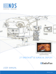
1
ENDOVUE 24 SURGICAL DISPLAY
High-Definition
User manual
[ English]
© 2009 NDS Surgical Imaging, LLC. All rights reserved.
Information in this document has been carefully checked for accuracy; however, no guarantee is given to
the correctness of the contents. This document is subject to change without notice. NDSsi provides this
information as reference only. Reference to products from other vendors does not imply any
recommendation or endorsement.
This document contains proprietary information protected by copyright. No part of this manual may be
reproduced by any mechanical, electronic, or other means, in any form, without prior written permission of
NDSsi.
NDS Surgical Imaging, NDSsi, Radiance and SmartSync are either registered or unregistered trademarks of
NDS Surgical Imaging. All other trademarks are the property of their respective owners.
Table of Contents
Tab 1
Safety Considerations --------------------------------------------------------------------------------ii
Declaration of Conformity ------------------------------------------------------------------------- iii
Legal Statement--------------------------------------------------------------------------------------- iii
Tab 2
About This Manual ------------------------------------------------------------------------------------1
Quick Startup -------------------------------------------------------------------------------------------1
Powering On The Unit--------------------------------------------------------------------------------1
First Time Users and Initial Test--------------------------------------------------------------------1
Tab 3
Connector Panel ----------------------------------------------------------------------------------------2
Electrical Symbols---------------------------------------------------------------------------------------3
Tab 4
Control----------------------------------------------------------------------------------------------------3
Image Adjustments -----------------------------------------------------------------------------------3
Brightness---------------------------------------------------------------------------------------------3
Contrast------------------------------------------------------------------------------------------------3
Backlight-----------------------------------------------------------------------------------------------3
Tab 5
Menu Systems Overview ----------------------------------------------------------------------------4
Video Source --------------------------------------------------------------------------------------------5
Display Set Up ------------------------------------------------------------------------------------------6
SD-SDI Picture Menu-------------------------------------------------------------------------------6
S-Video Picture Menu------------------------------------------------------------------------------6
Composite Picture Menu -------------------------------------------------------------------------6
VGA / RGBS Picture Menu ------------------------------------------------------------------------7
YPbPr Picture Menu --------------------------------------------------------------------------------7
DVI-Digital Picture Menu -------------------------------------------------------------------------8
Color Menus ------------------------------------------------------------------------------------------9
Setup Menu ---------------------------------------------------------------------------------------- 10
Defaults Menu ------------------------------------------------------------------------------------- 11
Tab 6
Troubleshooting ------------------------------------------------------------------------------------- 12
Tab 7
Drawing and Dimensions ------------------------------------------------------------------------- 13
Tab 8
Data Connectors and Pin Outs------------------------------------------------------------------- 14
Power Connector and Pin Out ------------------------------------------------------------------- 15
Tab 9
Specifications ----------------------------------------------------------------------------------------- 16
Video Inputs------------------------------------------------------------------------------------------- 17
Video Formats ---------------------------------------------------------------------------------------- 17
Cleaning Instructions ------------------------------------------------------------------------------- 17
Applications / Supported Devices ------------------------------------------------------------- 18
Safety Precautions----------------------------------------------------------------------------------- 19
Classification ------------------------------------------------------------------------------------------ 19
Product Disposal------------------------------------------------------------------------------------- 19
VESA Mounting--------------------------------------------------------------------------------------- 20
Contact ------------------------------------------------------------------------------------------------- 22
i
1
CAUTION
This symbol alerts the user that important literature concerning the operation of this unit has
been included. Therefore, it should be read carefully in order to avoid potential problems.
This symbol warns user that un-insulated voltage within the unit may have sufficient magnitude
to cause electrical shock. Therefore, it is dangerous to make contact with any part inside the unit.
To reduce the risk of electric shock, DO NOT remove cover (or back). There are no user
serviceable parts inside. Refer servicing to qualified service personnel.
To prevent fire or shock hazards, do not expose this unit to rain or moisture. Also, do not use this unit's
polarized plug with an extension cord receptacle or other outlets unless the prongs can be fully inserted.
The display is designed to meet the medical safety requirements for a patient vicinity device. This device
may not be used in connection with life support equipment.
Underwriters Laboratories (UL) Classification:
UL Safety Compliance:
This LCD monitor is U.L. Classified WITH RESPECT TO ELECTRIC SHOCK, FIRE AND MECHANICAL
HAZARDS ONLY IN ACCORDANCE WITH UL 60601-1/CAN/CSA C22.2 NO. 601.1.
EEC Safety Compliance:
This display unit meets the requirements of EN-60601-1 so as to conform to the Medical
Device Directive 93/42/EEC (general safety information).
This monitor complies to the above standards only when used with the supplied medical grade power
supply.
Power Supply: SL Power Electronic Corp MW155RA2400F02
AC Input: 100 to 240 Volts at 50 to 60 Hz.
DC Output: 24 volts
Power Cord: Use a hospital grade power cord with the correct plug for your power source.
The monitors should be powered from a center tapped circuit when used in the US at voltages over 120
volts. Monitor is intended for continuous operation.
This display is energized from an external electrical power source for class 1 equipment. It is the
responsibility of the installer to test the display’s earth ground to verify that it complies with the hospital,
local and national impedance requirements.
A ground post, located on the back of the display, may be used for the purpose of grounding the display’s
chassis. Any such ground must be installed in accordance with applicable electrical codes. The ground
post is shown on the mechanical drawing found on page 2.
Recycling:
Follow local governing ordinances and recycling plans regarding the recycling or disposal of this
equipment.
ii
Declarations of Conformity
FCC and Council Directives of European Standards:
This device complies with Part 15 of FCC rules and 93/42/EEC of the Council Directives of European Standards. Operation is subject
to the following two conditions: (1) This device may not cause harmful interference, and (2) this device must accept any
interference received, including interference that may cause undesirable results.
1. Use the attached specified cables with the color monitor so as not to interfere with radio and television reception. Use of
other cable and adapters may cause interference with other electronic equipment.
2. This equipment has been tested and found to comply with the limits pursuant to FCC part 15 and CISPR 11. This equipment
generates, uses and can radiate radio frequency energy and, if not installed and used in accordance with the instructions, may
cause harmful interference to radio communications.
IEC:
This equipment has been tested and found to comply with the limits for medical devices to the IEC 60601-1-2:2001. These limits
are designed to provide reasonable protection against harmful interference in a typical medical installation. This equipment
generates, uses and can radiate radio frequency energy and, if not installed and used in accordance with the instructions, may
cause harmful interference to other devices in the vicinity.
FCC, Council Directives of European Standards and IEC:
There is no guarantee that interference will not occur in a particular installation. If this equipment does cause harmful interference
to radio or television reception, which can be determined by turning the equipment off and on, the user is encouraged to try to
correct the interference by one or more of the following measures:
•
Reorient or relocate the receiving antenna.
•
Increase the separation between the equipment and receiver.
•
Connect the equipment into an outlet on a circuit different from that to which the receiver is connected.
•
Consult your dealer or an experienced radio/TV technician for help.
Accessory equipment connected to this monitor must be certified according to the respective IEC Standards (i.e., IEC 60950-1) for
data processing equipment and IEC 60601-1 for medical equipment). Furthermore, all configurations shall comply with the system
standard, IEC 60601-1-1. Anyone who connects additional equipment to the signal input part or signal output part configures a
medical system, and is therefore responsible that the system complies with the requirements of system standard IEC 60601-1-1.
Whoever is responsible for securing the monitor to a system needs to insure that the mounting equipment used with this display
complies to IEC standard 60601-1. If in doubt, consult the technical services department or your local representative.
Legal Statement
NDS sells its products through other medical device manufacturers, distributors and resellers and therefore, purchasers of this NDS
product should consult with the entity through which this product was originally purchased regarding the terms of any applicable
product warranties provided by such entity, if any.
NDS neither assumes nor authorizes any person to assume for it any other liabilities in conjunction with and/or related to the sale
and/or use of its products. To ensure proper use, handling and care of NDS products, customers should consult the product
specific literature, instruction manual, and/or labeling included with the product or otherwise available.
Customers are cautioned that system configuration, software, the application, customer data and operator control of the system,
among other factors, affect the product’s performance. While NDS products are considered to be compatible with many systems,
specific functional implementation by customers may vary. Therefore, suitability of a product for a specific purpose or application
must be determined by the consumer and is not warranted by NDS.
NDS SPECIFICALLY DISCLAIMS ALL WARRANTIES OF ANY KIND, WHETHER EXPRESS, IMPLIED AND/OR STATUTORY,
INCLUDING, BUT NOT LIMITED TO WARRANTIES OF MERCHANTABILITY, FITNESS AND/OR OF SUITABILITY FOR A
PARTICULAR PURPOSE, AND NON-INFRINGEMENT WITH RESPECT TO ALL NDS PRODUCTS OR SERVICES. ANY AND ALL
OTHER WARRANTIES, REPRESENTATIONS AND/OR GUARANTEES, OF ANY TYPE, NATURE OR EXTENT, BE IT IMPLIED,
EXPRESS AND/OR WHETHER ARISING UNDER OR AS A RESULT OF ANY STATUTE, LAW, COMMERCIAL USAGE, CUSTOM,
TRADE OR OTHERWISE, ARE HEREBY EXPRESSLY EXCLUDED AND DISCLAIMED.
NDS, its suppliers and/or distributors are not liable, directly or by way of indemnity for any special, incidental, consequential,
punitive, exemplary or indirect damages, including but not limited to alleged damages for delayed shipment, non-delivery,
product failure, product design or production, inability to use such products or services, loss of future business (lost profits), or
from any other cause, whatsoever, in connection with or arising from the purchase, sale, lease, rental, installation or use of such
NDS products, these terms and conditions, or with respect to any the terms of any agreement which incorporates these terms and
conditions.
SOME JURISDICTIONS DO NOT ALLOW EXCLUSIONS AND DISCLAIMERS OF CERTAIN WARRANTIES OR LIMITATIONS OF
LIABILITY, SO THE LIMITATIONS AND/OR EXCLUSIONS, SET FORTH HEREIN, MAY NOT APPLY. IN THAT EVENT LIABILITY
WILL BE LIMITED TO THE GREATEST EXTENT PERMITTED BY LAW IN THE SUBJECT JURISDICTION.
The information provided in this document, including all designs and related materials, is the valuable property of NDS and / or its
licensors and, as appropriate, they reserve all patent, copyright, and other proprietary rights to this document, including all design,
manufacturing reproduction, use, and sales rights thereto, except to the extent said rights are expressly granted to others.
iii
About This Manual
2
This manual is designed to assist the user with proper installation, setup and operation of the EndoVue
LCD display. Depending on the model and options that were purchased, some of the features and options
in this manual may not apply to the display you are using.
A black numbered tab on the side of the page denotes the beginning of a section.
The functional descriptions in this manual are representative of:
Part Numbers: 90K0001(Except U.S. A. and Canada) and 90K0004 (U.S. A. and Canada only)
Firmware BIOS: 58M0001, A06 Version and later.
Note: This BIOS supports both High Definition SDI (HD SDI) and Standard Definition SDI (SD SDI).
Manual Part Number: 60G0410 Rev C
Intended Use and Contraindications
Intended Use:
This monitor is intended for use in a medical environment to display high quality video and graphic
images .
Contraindications:
The monitor may not be used in the presence of flammable anesthetics mixture with air, oxygen or nitrous
oxide.
For mission critical applications, we strongly recommend that a replacement unit be immediately
available.
Quick Startup
Powering On The Unit:
Connect the power supply to the display via the power plug. Plug in the AC adapter. Connect a video
source to the display. Apply power to the peripheral device, then to the display. The power switch location
is shown on page 13. The NDS logo is displayed, followed shortly by video.
The electronics, designed by NDS, incorporates proprietary SmartSync™ technology which at initialization,
examines the incoming signal and automatically displays the video image in its proper format. This
eliminates adjustments for most video sources. To fine tune the image, please refer to “Image
Adjustments” on page 3.
First time users and initial test:
Visually, Flat-Panel (LCD) images will look crisper than those of a traditional CRT. For the same reason, live
video may appear a little blocky. Users not familiar with the image differences should familiarize
themselves before utilization in a critical application and determine its usability. It is recommended that
first time users view the display next to a CRT to familiarize themselves with any subtle differences in
viewing quality.
1
Connector Panels
3
Notes
1. DC IN power supply cord shall be reliably fixed and not be removable without the use of a TOOL.
2. The 5V/1A DC output is protected Auxiliary connection. See page 15 for details.
Electrical Symbols
Equipotentiality: connector to other equipment (earth equipotential)
This symbol appears next to the display’s Potential Equalization Conductor. (ground post)
Open (Off) Switch:
This symbol appears on the open, or off, side of the display’s rocker switch.
Closed (On) Switch:
This symbol appears on the closed, or on, side of the display’s rocker switch.
Alternating Current
Direct Current
2
Control
The display is controlled via a 6 button keypad. The keypad, located on the bottom front of the display,
allows the user to make adjustments to various display parameters using the On Screen Menus (OSM)
system.
4
Image Adjustments
Adjust Brightness
Press the Brightness / Contrast button to display the Brightness control.
Press the ◄ or ► button to increase or decrease brightness. Setting the
brightness too high or too low will decrease the amount of visible
grayscales.
Adjust Contrast
Press the Brightness / Contrast button twice to display the Contrast control.
Press the ◄ or ► button to adjust the contrast. Setting the contrast too
high or too low causes loss of some grayscales. Color saturation may
appear incorrect.
Adjust Backlight
Press the Brightness / Contrast button three times to display the Backlight
control. Press the ◄ or ► button to set the backlighting.
Note: Lowering the backlight level will increase the backlight lifetime.
3
Menu Systems Overview
Press the MENU button once to open the Menu System. The current video input and its resolution are
shown in the Display Mode tab on the top right of the menu. The Menu System opens with Picture menu
displayed. Press the ◄ or ► button to select the menu you want to work with, then press the SCROLL
button to select the parameter. Press the ◄ or ► button to set the parameter to the desired value. Press
the MENU button to save your changes and close the Menu System.
Notes:
1. All parameter names change to the language selected in the Setup Menu.
2. Grayed out parameters are not accessible.
5
Language List
English
Português Polski
Deutsch
Norsk
한국어
Français
Dansk
日本語
Italiano
Suomi
简体中文
Svensk
Türkçe
繁體中文
Español
Ελληνικά
Nederlands Русский
4
Video Source
Inputs Menu
When the display is powered on Auto Source Select looks at the previously selected video source first. If a
signal is present it is displayed, otherwise Auto Source Select starts scanning the inputs for a signal.
To switch to a different input source, press the INPUT button to open the input menu. The Input menu
shows: selected to the right of the active input. Press the SCROLL button to highlight the desired input.
Finally, press the ◄ button to select it.
5
Setting Up the Display
SDI Picture Menu
S-Video Picture Menu
Composite Picture Menu
Horizontal Position
Moves the image to the left or right. Press ◄ or ► to horizontally center the image.
Vertical Position
Moves the image up or down. Press ◄ or ► to vertically center the image.
Sharpness
Press ◄ or ► to adjust the sharpness (focus) of the displayed image.
Overscan (Video)
This parameter is enabled when the input is video (camera) data.
0 = The image is displayed at a size that fills the screen without losing any video information. The image
presented to the display may include black bars top and bottom or left and right.
1, 2, 3, 4, 5 or 6 = The image is linearly enlarged, while remaining centered, in incremental steps. As the
image becomes larger video information will be lost from the top and bottom and / or left and right.
Select using ◄ or ► buttons.
Video Format
Auto = Automatically sets the unit to the format of the connected video source. NTSC = Sets the unit to
accept NTSC video. PAL = Sets the unit to accept PAL video. Select using ◄ or ► buttons.
6
VGA / RGBS Picture Menu
YPbPr Picture Menu
Horizontal Position
Moves the image to the left or right. Press ◄ or ► to horizontally center the image.
Vertical Position
Moves the image up or down. Press ◄ or ► to vertically center the image.
Sharpness
Press ◄ or ► to adjust the sharpness (focus) of the displayed image. Note: When the VGA input is active
Sharpness cannot be adjusted when the display is operating at native resolution.
Phase
Press ◄ or ► to adjust the phase of the display’s pixel clock.
Frequency
Adjusts the frequency of the display’s pixel clock. With Scaling set to Fill adjust until image just fills the
screen horizontally. Press ◄ or ► to adjust the frequency of the display’s pixel clock.
Overscan (Video)
This parameter is enabled when the input is video (camera) data.
0 = The image is displayed at a size that fills the screen without losing any video information. The image
presented to the display may include black bars top and bottom or left and right.
1, 2, 3, 4, 5 or 6 = The image is linearly enlarged, while remaining centered, in incremental steps. As the
image becomes larger video information will be lost from the top and bottom and / or left and right.
Select using ◄ or ► buttons.
Scaling (Graphics)
This parameter is enabled when the input is graphics (computer) data.
Fill = Expands the video image to fill the entire screen. The aspect ratio may not be accurately displayed.
Aspect = Expands the video image until its largest dimension fills the screen. Image may be displayed with
black bars on the top and bottom or the left and right. 1:1 = Displays the video data in its native size and
aspect ratio. Image may be displayed with black bars on the top and bottom and on the left and right.
Select using ◄ or ► buttons.
SmartSync / Alternate Modes
On initialization NDS’ proprietary SmartSync technology examines the incoming signal and automatically
displays the video image in its proper format. To run SmartSync select the SmartSync / Alternate Modes
parameter and press the ◄ button. An Alternate Mode may be selected by pressing the ► button.
The Alternate Mode (format) parameter has two arguments X and Y. The left (X) argument is the current
mode and the right (Y) is the number of modes available. The mode (format) and / or Frequency changes
each time the ► button is pressed. When the mode count reaches its maximum the next ► button press
returns the mode count to 1.
7
DVI Digital Picture Menu
Overscan (Video)
This parameter is enabled when the input is video (camera) data.
0 = The image is displayed at a size that fills the screen without losing any video information. The image
presented to the display may include black bars top and bottom or left and right.
1, 2, 3, 4, 5 or 6 = The image is linearly enlarged, while remaining centered, in incremental steps. As the
image becomes larger video information will be lost from the top and bottom and / or left and right. Select using ◄ or ► buttons.
Scaling (Graphics)
This parameter is enabled when the input is graphics (computer) data.
Fill = Expands the video image to fill the entire screen. The aspect ratio may not be accurately displayed.
Aspect = Expands the video image until its largest dimension fills the screen. Image may be displayed with
black bars on the top and bottom or the left and right. 1:1 = Displays the video data in its native size and
aspect ratio. Image may be displayed with black bars on the top and bottom and on the left and right. Select using ◄ or ► buttons.
8
Color
Menus
Color
ColorMenus
Menus
VGA / RGBS, DVI-A / RGBS, DVI-D
SDI, S-Video, Composite, YPbPr, DVI-YPbPr
Gamma (for graphic mode, e.g. 1920 x 1200 / 60.0 Hz)
Press ◄ or ► to select a preset Gamma, Video or PACS
Notes:
1. Video is a color corrected Look Up Table (LUT) available with DVI and VGA.
2. Picture Archive Communications System (PACS) is a DICOM-like LUT available with DVI and VGA.
Saturation (for video mode, e.g. 1920 x 1080p / 30.0 Hz)
Press ◄ or ► to set the saturation (color intensity) of the image.
Red, Green, Blue (for both graphic & video mode)
Press the ◄ or ► button to increase or decrease the intensity of the selected color.
Hue (for video mode, e.g. 1920 x 1080p / 30.0 Hz)
Press ◄ or ► to set the hue (color tint) of the image.
9
9
Setup Menu
Menu Position
Places the menu in 1 of 9 predefined screen positions. Press the ◄ or ► button to select any of the 9
screen positions.
Language
Selects 1 of 19 languages: English, Deutsch, Francais, Italiano, Nederlands, Espanol, Dutch, etc. Press the ◄
or ► button to select any of the 19 languages.
DPMS Enable
Display Power Management System. When DPMS is enabled (on), and no input signal is present, an
“Entering Power-Save Mode” message is displayed for 10 - 15 seconds, after which the display shuts down.
This prolongs the life of the backlight tubes in the display. The display turns on when the input signal is
restored. Press the ► button to enable DPMS, press the ► button to disable DPMS.
Auto Source Select
on = Searches through all possible input sources until an active video source is found. off = Video input is
manually selected. Press the ◄ or ► button to disable or enable Auto Source Select.
Menu Lock
Disables access to menu system. This prevents inadvertent changes to the display’s settings. To enable
Menu Lock, press the ► button. MENU LOCKED is displayed when the ► button is pressed. To unlock,
simultaneously press and hold the MENU and SCROLL buttons until MENU UNLOCKED is displayed.
Operating Hours: Backlight hours of operation.
BIOS: Version of the display’s BIOS firmware.
10
Defaults Menu
Factory Defaults
Displays Restoring Factory Defaults message and returns all settings to their factory preset values. Press
the SCROLL button to highlight Factory Defaults, then press the ► button.
User Defaults
Allows up to five customized user settings to be saved.
Setting User Defaults
1. Set the Picture, Color and Setup parameters to the user’s preferences.
2. Select the Defaults tab.
3. Use the SCROLL button to select an available User Defaults. ***EMPTY*** appears in available User
Defaults.
4. Press the ◄ to save the user’s settings. The ***EMPTY*** message will be removed, see User Defaults 1
in the above OSM illustration.
5. Repeat steps 1 thru 4 for up to 5 users.
Restoring User Defaults
1. Select the User Defaults to be restored, then press the ► button .
Clearing User Defaults
1. Select the User Defaults to be cleared, then press the Brightness / Contrast button .
Note: The prompt at the bottom of the Defaults menu appears only when one of the User Defaults is
selected.
11
Troubleshooting Section
Image Size is Very Large for the Screen
If the computer data does not appear to be the correct format, then SmartSync™ must be run. To run
SmartSync™, press the Menu button. Select the Setup menu. Press SCROLL to highlight SmartSync™ , then
press the ◄ button. SmartSync™ will run and size the image properly.
Ghosting in Characters
Ghosting in characters is usually attributed to reflections in the video cable or source. Use a high quality
coaxial cable and, if possible, lower the vertical refresh rate. Lower scan rates can help eliminate reflections.
Unlike a CRT a flat-panel will not flicker at lower refresh rates (60 Hz is optimal) and data update will be the
same at all refresh rates.
Text is Too Small
Since the monitor accepts and displays computer data with a higher resolution than the display’s native
resolution, this may produce small text. In the Menu check the Display Mode tab. Verify that the computer
data resolution does not exceed the Native Resolution specification shown on page 16.
Character Jitter
If text characters seem to be “shaky” or bold, then Sharpness, Frequency and / or Phase may require
adjusting. See: Setting Frequency, Phase and Sharpness below.
Character Noise and Vertical Distortion
The Frequency adjustment expands or contracts the horizontal size of the displayed image. The displayed
image may be too wide or too narrow and vertical banding and pixel jitter may appear in grays and light
colors. Adjust the Frequency until the image just fits the screen. Horizontal position adjustment can be
used to verify that Frequency is set correctly. Line up the image on the left edge of the screen and then
shift by one “click” to the right. The image should have one column off the screen on the right side if the
Frequency is set correctly.
Black Screen
Power the display Off and On. If the NDS logo appears then the display is working properly. Check if the
power management feature (DPMS) is enabled. A “Searching” message appears when the video source is
not present or when an input source is out of the display’s resolution range.
Setting Frequency, Phase and Sharpness
Windows Users: Open a WordPad document and set the font to Arial 8. Press the enter key to move the
cursor to the middle of the page. Hold the shift and + keys down to create a line of +s.
If the + signs appear in groups of light or dark, then the Frequency is not correct. Press the MENU button
to open the OSM, then SCROLL to the Frequency parameter. Press the ◄ or ► buttons to increase or
decrease Frequency. There will be a point were all the + signs snap into focus and are the same intensity.
Phase and Sharpness are subtle adjustments and are best set using a display calibration program.
12
6
Drawing and Dimensions
7
Power Switch
13
Data Connectors and Pin Outs
DVI-I*
VGA / RGBS / YPbPr
1 RED
6 GND RED
11 ID0
2 GREEN
7 GND GREEN
12 ID1
3 BLUE
8 GND BLUE
13 HORIZ SYNC
4 ID2
9 N. C.
14 VERT SYNC.
5 GND
10 SYNC GND
15 ID3
S-Video
Pin Name
Description
Digital & Analog
DVI-I supports digital and analog (RGBS/YPbPr).
Analog data appear on pin 8 and pins, C1 through C5.
* Compliant with DVI 1.0
SIGNAL
PIN#
SIGNAL
1
T.M.D.S. DATA 2-
16
HOT PLUG DETECT
2
T.M.D.S. DATA 2+
17
T.M.D.S. DATA 0-
3
T.M.D.S. DATA 2/4 SHIELD
18
T.M.D.S. DATA 0+
4
T.M.D.S. DATA 4-
19
T.M.D.S. DATA 0/5 SHIELD
5
T.M.D.S. DATA 4+
20
T.M.D.S. DATA 5-
6
DDC CLOCK
21
T.M.D.S. DATA 5+
PIN#
1
GND Ground (Y)
7
DDC DATA
22
T.M.D.S. CLOCK SHIELD
2
GND Ground (C)
8
ANALOG VERT. SYNC
DVI 2 Only
23
T.M.D.S. CLOCK+
9
T.M.D.S. DATA 1-
24
T.M.D.S. CLOCK-
10
T.M.D.S. DATA 1+
11
T.M.D.S. DATA 1/3 SHIELD
C1
ANALOG RED
12
T.M.D.S. DATA 3-
C2
ANALOG GREEN
13
T.M.D.S. DATA 3+
C3
ANALOG BLUE
14
+5V POWER
C4
ANALOG HORIZ SYNC
15
GND
C5
ANALOG GROUND
3
Y
Intensity (Luminance)
4
C
Color (Chrominance)
Serial Control
Pin Name
1
NC
Description
No Connection
2
RXD Flash Upgrade Receive Data
3
TXD Flash Upgrade Transmit Data
4
NC
5
RGBS & YPbPr (DVI)
No Connection
GND Ground
6
NC
No Connection
7
NC
No Connection
8
NC
No Connection
9
RXD Flash Upgrade Receive Data
14
8
Power Connectors and Pin Out
24 volt connector
Pin
X
Z
Y
1
2
3
+ 24
VDC
GND
Shield
5 Volt Connectors
CUI P/N PP-015
SMK P/N LLP-0143
5 Volt Connector Wiring
15
Connector
Center Pin
Shell
CUI P/N PP-015
+ 5 VDC
Return
SMK P/N LLP-0143
+ 5 VDC
Return
Specifications1
Viewable Diagonal (inches)
24.0
Brightness2 (cd/m2, typical)
400
Native Resolution
1920 x 1200
Dot Pitch (mm)
.270
Vertical Viewing Angle
130°
Horizontal Viewing Angle
150°
Contrast Ratio (typical)
1300:1
VGA Input signal level at 75 Ohm
0.7 V p-p
HD-SDI Input signal level
0.8 to 2.0 V p-p
S-Video Input signal level
0.7 V p-p
Composite Input signal level
0.7 V p-p
RGBS Input signal level
0.7 V p-p
RGBS Input Sync level
0.4 to 4.0 V p-p
DC Power Consumption (nominal) 3
115W
AC Power Consumption (nominal) 3
125W
Display Weight
16.1 lbs (7.3 kg)
9
Environmental
Operating Temperature
0 to 350C
Operating Humidity (non condensing)
30 to 75%
Storage/Transport Temperature
-20 to 500C
Storage/Transport Humidity (non condensing)
5-85%
Altitude, operating
0 - 3,000 meter
Altitude, non-operating
0 - 12,000 meter
Notes:
1. Specifications are subject to change without notice. Contact factory for current specifications.
2. Brightness shown is without a Touch Screen or A/R filter installed.
3. Applies to the SL Power Electronic Corp MW155RA2400F02 power supply provided with the display.
AC input: 100 to 240 Volts at 50 to 60 Hz.
16
Video and Graphics Inputs
Connector Type
HD-SDI / SDI
BNC, 75 Ohm terminated
S-video
DIN-4, 75 Ohm terminated
RGBS / YPbPr
DVI-A, 75 Ohm terminated
RGBS / YPbPr
HD-15, 75 Ohm terminated
Composite
BNC, 75 Ohm terminated
DVI
DVI-D
VGA
HD-15
Video Formats
Horiz.
Interlaced / Aspect
Freq (kHz) Progressive
Standard
Digital/Analog
576/50i (PAL) SDI, Comp, S-video, RGBS, YPbPr
15.625
Interlaced
4:3
SMPTE 259M/C ITU 601
480/60i (NTSC) SDI, Comp, S-video, RGBS, YPbPr
15.734
Interlaced
4:3
SMPTE 259M/C ITU 601
576/50p RGBS, YPbPr, DVI
31.250
Progressive
4:3
ITU-R-BT1358
480/60p RGBS, YPbPr, DVI
31.469
Progressive
4:3
SMPTE 293M
720/50p RGBS, YPbPr , HD-SDI, DVI
37.500
Progressive
16:9
SMPTE 292M, SMPTE 296M
720/60p RGBS, YPbPr , HD-SDI, DVI
45.000
Progressive
16:9
SMPTE 296M, SMPTE 292M
1080/50i RGBS, YPbPr , HD-SDI, DVI
28.125
Interlaced
16:9
SMPTE 274M, SMPTE 292M
1080/60i RGBS, YPbPr , HD-SDI, DVI
33.750
Interlaced
16:9
SMPTE 274M, SMPTE 292M
1080/50p RGBS, YpbPr, HD-SDI, DVI
56.200
Progressive
16:9
SMPTE 274M
1080/60p RGBS, YPbPr , HD-SDI, DVI
67.300
Progressive
16:9
SMPTE 274M
Serial Digital and Analog
Cleaning Instructions
We recommend turning the display off prior to cleaning.
Follow your organization’s protocol for the handling of blood and body fluids. Clean the display
with a diluted mixture of mild detergent and water. Use a soft towel or swab. Use of certain
cleaning agents may cause degradation to the plastic enclosure and labels of the product. The plastic is
ABS. Consult the cleanser manufacturer to see if the agent used is compatible with ABS. Do not allow liquid
to enter the display.
17
Applications / Supported Devices
Fully compliant for medical use in surgery, the EndoVue™ widescreen from NDSsi offers a high quality,
low-cost solution for surgical imaging environments. Its compact and lightweight design makes it very
maneuverable and easy to install on a surgical cart or boom arm. The new EndoVue™ is an affordable
alternative to a full-featured surgical display but can still accommodate high-definition signals from a
variety of medical imaging sources, including endoscopes, ultrasound, PACS, and vital signs. It also
features a fanless cooling design to minimize the risk of spreading airborne contaminates near the sterile
field.
SOURCE
• DVI, HD-SDI
• HD-RGBS, HD-YPbPr
• RGBS, YPbPr , SDI
• S-Video, Composite
• VGA
APPLICATION
• HD Endoscopy, PACS, Vital Signs, Room Camera
• HD Endoscopy
• SD Endoscopy
• Fluoroscopy, SD Endoscopy, Ultrasound
• PACS, Endoscopy, Ultrasound, Angiography
18
Safety Precautions, Classification, Product Disposal
Safety Precautions
• To prevent the risk of electric shock, make sure power cord is unplugged from wall socket. To fully
disengage the power to the unit, please disconnect the power cord from the ac outlet.
• Grounding reliability can only be achieved when the equipment is connected to an equivalent
receptacle marked “Hospital Only” or “Hospital Grade”.
• The signal input parts or signal output parts (SIP/SOP) need to be connected properly and any unused
SIP/SOP shall not be accessible to unqualified personnel after the LCD is integrated into a medical
system.
Classification
• Power by Class I power Adapter.
• No Applied Part.
• Ingress Protection: IPX0 (Front side can meet IP32 (3: opening size, minor dim. ≤ 2.5mm; 2: dripping
water (front only), ± 15° from vertical))
• Mode of operation: Continuous Operation
• The equipment not suitable for use in the presence of a flammable anesthetic mixture with air or with
oxygen or nitrous oxide: Not AP or APG Category.
Product Disposal
• Outside the European Union - If you wish to dispose of used electrical and electronic
products outside the European Union, please contact your local authority so as to comply
with the correct disposal method.
•
Within the European Union:
EU-wide legislation, as implemented in each Member State, requires that waste electrical and
electronic products carrying the mark (left) must be disposed of separately from normal household waste.
This includes monitors and electrical accessories, such as signal cables or power cords. When you need to
dispose of your display products, please follow the guidance of your local authority, or ask the shop where
you purchased the product. The mark on electrical and electronic products only applies to the current
European Union Member States.
19
VESA Mounting
Install VESA Mounting
The LCD display provides standard VESA (100mm) mounting allowing the display to be conveniently
integrated a system. Installation should be performed by a qualified technician. Please contact your
provider’s service department if you require assistance installing the display.
VESA mounting dimension diagram (100 x 100 mm)
Installation instructions follow:
The wall-mounting attachment is comprised of one mounting bracket and screws.
Attach the mounting bracket to the rear cover of the LCD display using the provided (M4 type) screws.
The mounting bracket must be securely tightened. Failure to properly secure the display to the
mounting bracket could be hazardous.
CL
100mm
Monitor Mounting Detail
20
Notes
Notes
Notes
WWW.NDSSI.COM
Corporate Headquarters
NDS Surgical Imaging
5750 Hellyer Avenue
San Jose, CA 95138
USA
Tel: 408.776.0085
Fax: 408.776.9878
EMail: [email protected]
Europe Headquarters
NDS Surgical Imaging BV
Nijverheidscentrum 28
2761 JP Zevenhuizen (ZH)
The Netherlands
Tel: 0031 180 63 43 56
Fax: 0031 180 63 21 91
E Mail: [email protected]
Japan Headquarters
NDS Surgical Imaging K.K.
Takanawa Kaneo Bldg., 6F
3-25-22 Takanawa
Minato-ku Tokyo 108-0074
Japan
Tel: +81-3-5475-1835
Fax: +81-3-5475-2835
Email: [email protected]
60G0410
Author: Walt Thompson 2010