1
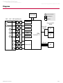
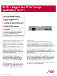
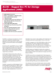
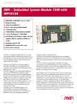
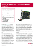
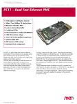
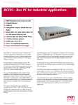
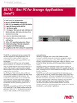
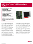
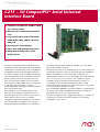
Embedded Solutions
for Transportation and Industrial Markets
www.men.de/products/02G215-.html
G215 – 3U CompactPCI® Serial Universal
Interface Board
n 5 interfaces at 8 HP front: 2 UARTs, 2 CAN
bus, 1 binary I/O port
n Other function combinations via FPGA IP
cores
n For protocols/physical layers like RS232/
RS422/RS485, HDLC, CAN bus, IBIS, GPS,
binary I/O
n Physical layers via SA-Adapters
n -40 to +85°C with qualified components
n PICMG CPCI-S.0 CompactPCI® Serial
peripheral card
The G215 is a universal interface board based on 3U
CompactPCI® Serial. The physical layer can be realized
individually for each channel by means of SA-Adapters.
SA-Adapters are small universal boards providing the
line drivers for legacy serial I/O, fieldbus interfaces and
other small I/O functions. Most SA-Adapters use 9-pin
D-Sub connectors which are accessible at the front
panel. Alternatively, the adapter can be connected to
the front panel via ribbon cable. The SA concept allows
to add additional I/O interfaces to the G215,
enhancing flexibility with regard to the line transceivers
and isolation requirements.
Two SA-Adapters can be mounted directly on the
G215, the other maximum six adapters need more
front-panel space and are connected to the carrier via
ribbon cable. The G215 comes in a standard
configuration with five pre-defined functions on 8 HP:
two CAN interfaces, two UARTs and one 8-channel
binary I/O interface. SA-Adapters are not included in
G215 Data Sheet / 2013-02-06
the delivery, because different types are available, e.g. for the UARTs.
They can be ordered as needed.
The board's I/O functions are realized by means of an FPGA, making it a
very flexible, inexpensive solution for dedicated serial I/O. The card can
become "everything" from a customized I/O combination to a
specialized 8-port CAN card or even an intelligent I/O board including a
Nios® soft core, on 4, 8 or 12 HP. As an option, further I/O signals,
including high-speed interfaces, can be accessed via rear I/O on
CompactPCI® Serial connectors P3 and P4. The FPGA is loaded
automatically after power-up from a 4 MB serial Flash. It is also possible
to access this Flash to update its contents.
Up to 64 MB DDR2 SDRAM are optionally available for complementing
the functions of the FPGA. This DRAM can be used for example as a
large buffer memory for more complex protocols.
The G215 is designed for use in rugged environments. For example, all
components are soldered-on and are specified for an operating
temperature of -40 to +85°C.
Page 1
Embedded Solutions
for Transportation and Industrial Markets
www.men.de/products/02G215-.html
Diagram
DDR2 RAM
F
Front connector
SA
SA-Adapter™
Options
4 HP 4 HP 4 HP (additional)
F
SA
B
CAN bus
F
SA
B
CAN bus
F
SA
UART
F
SA
UART
SA
F
F
B
Binary I/O
CompactPCI®
Serial
Rear I/O
signals
FPGA
Cyclone™ IV
P4
P3
SA
PCIe x4
G215 Data Sheet / 2013-02-06
F
SA
B
F
SA
B
Custom I/O
P1
Page 2
Embedded Solutions
for Transportation and Industrial Markets
www.men.de/products/02G215-.html
Technical Data
I/O Interfaces
n
n
n
n
Different variations possible through FPGA IP cores and SA-Adapters:
o RS232
o RS422
o RS485
o IBIS master/slave
o CAN bus
o HDLC
o Binary I/O
o GPS
o The FPGA offers the possibility to add customized I/O functionality. See FPGA.
o Option matrix showing possible IP cores and SA-Adapters (PDF)
Accessible via onboard connectors
o Physical interface at front panel using SA-Adapters
o Two interfaces for direct onboard connection of SA-Adapters
o Up to six interfaces for connection of SA-Adapters via 10-pin ribbon cable
Standard factory interface configuration:
o 8 HP front panel with five SA-Adapter cut-outs for
o 2 CAN bus interfaces
o 2 UART interfaces
o 1 binary I/O interface
o No SA-Adapters included by standard; they can be selected as needed
Standard factory FPGA configuration:
o 16Z029_CAN - CAN controller (controls CAN X1)
o 16Z029_CAN - CAN controller (controls CAN X2)
o 16Z125_UART - UART controller (controls UARTs X3/X4)
o 16Z037_GPIO - GPIO controller (8 I/O lines on X5)
Memory
n
4 MB serial Flash for FPGA configuration
Miscellaneous
n
Four status LEDs at front panel
o One status LED to signal FPGA configuration (interfaces ready)
o Three user LEDs, FPGA-controlled by 16Z034_GPIO controller
CompactPCI® Serial
n
Compliance with CompactPCI® Serial PICMG CPCI-S.0 Specification
Peripheral slot
Host interface:
®
o One PCI Express x4 link
®
o PCIe 1.x support
o Data rate 1 GB/s in each direction (2.5 Gbit/s per lane)
n
n
Electrical Specifications
n
Supply voltage/power consumption:
o +12 V (-5%/+5%), 0.125 A
Mechanical Specifications
n
Dimensions: conforming to CompactPCI® Serial specification for 3U boards
Front panel: 8 HP with ejector
o For up to five interfaces
Weight: 168 g (w/o SA-Adapters)
n
n
G215 Data Sheet / 2013-02-06
Page 3
Embedded Solutions
for Transportation and Industrial Markets
www.men.de/products/02G215-.html
Technical Data
Environmental Specifications
n
Temperature range (operation):
o -40..+85°C (qualified components)
o Airflow: min. 1.0 m/s
Temperature range (storage): -40..+85°C
Relative humidity (operation): max. 95% non-condensing
Relative humidity (storage): max. 95% non-condensing
Altitude: -300 m to +3000 m
Shock:
o 15 g, 11 ms (EN 60068-2-27)
o 50 m/s², 30 ms (EN 61373)
Bump: 10 g, 16 ms (EN 60068-2-29)
Vibration (sinusoidal): 1 g, 10 Hz - 150 Hz (EN 60068-2-6)
Vibration (function): 1 m/s², 5 Hz - 150 Hz (EN 61373)
Vibration (lifetime): 7.9 m/s², 5 Hz - 150 Hz (EN 61373)
Conformal coating on request
MTBF
n
529 954 h @ 40°C according to IEC/TR 62380 (RDF 2000)
Safety
n
PCB manufactured with a flammability rating of 94V-0 by UL recognized manufacturers
EMC
n
Tested according to EN 55022 (radio disturbance), IEC 61000-4-2 (ESD) and IEC 61000-4-4 (burst)
Software Support
n
Driver software for Windows®, Linux, VxWorks®, QNX®
Flash update tools for Windows®, Linux, VxWorks®
For more information on supported operating system versions and drivers see Downloads.
n
n
n
n
n
n
n
n
n
n
n
n
FPGA
This product offers the possibility to add customized I/O functionality in FPGA.
Flexible Configuration
n
n
n
FPGA Capabilities
n
n
n
n
n
n
n
G215 Data Sheet / 2013-02-06
Customized I/O functions can be added to the FPGA.
It depends on the board type, pin counts and number of logic elements which IP cores make sense and/or
can be implemented. Please contact MEN for information on feasibility.
You can find more information on our web page "User I/O in FPGA"
FPGA Altera® Cyclone® IV EP4CGX30 (Standard)
o 29 440 logic elements
o 1080 Kbits total RAM
FPGA Altera® Cyclone® IV EP4CGX75 (Option)
o 73 920 logic elements
o 4158 Kbits total RAM
FPGA Altera® Cyclone® IV EP4CGX150 (Option)
o 149 760 logic elements
o 6480 Kbits total RAM
For interface functions
4 MB external Flash for FPGA configurations
Connection
o Pin count on onboard SA-Adapter connectors: 64 pins
o SA-Adapters are used to realize the physical lines.
®
o Option: Connection via CompactPCI Serial rear I/O P3 and P4, pin count: 128 pins
Functional updates via software
o MEN offers Flash update tools for different operating systems.
Page 4
Embedded Solutions
for Transportation and Industrial Markets
www.men.de/products/02G215-.html
Configuration & Options
Standard Configurations
Article No.
Front Panel
FPGA Cores
Operating Temperature
02G215-00
8 HP, 5 D-Sub slots
2 CAN, 2 UARTs, 1 binary I/O (8bit)
-40..+85°C
Options
Physical Layers
n
n
Via up to eight SA-Adapters
Different variations possible through FPGA IP cores and SA-Adapters:
o RS232
o RS422
o RS485
o IBIS master/slave
o CAN bus
o HDLC
o Binary I/O
o GPS
o Other physical layers dependent on FPGA configuration
o Option matrix showing possible IP cores and SA-Adapters (PDF)
FPGA
n
FPGA Altera® Cyclone® IV EP4CGX30, EP4CGX75 or EP4CGX150, see FPGA
Memory
n
16 MB, 32 MB, 64 MB DDR2 SDRAM, FPGA-controlled, e.g., as a buffer memory for more complex
protocols
Rear I/O
n
Up to 128 I/O signals on CompactPCI® Serial connectors P3 and P4
o FPGA-controlled
o Also for high-speed interfaces
o In addition to SA-Adapter I/O
Mechanical
n
4, 8 or 12 HP front panel dependent on number of SA-Adapters
o 4 HP with 2 onboard SA-Adapters
o 8 HP with 5 SA-Adapters (standard)
o 12 HP with 8 SA-Adapters
One-piece front panel
n
Operating Temperature
n
Depends on system configuration
Maximum: +85°C
Minimum: -50°C
n
Also available with conduction cooling in MEN CCA frame
n
n
Cooling Concept
Please note that some of these options may only be available for large volumes. Please ask our sales staff for more information.
G215 Data Sheet / 2013-02-06
Page 5
Embedded Solutions
for Transportation and Industrial Markets
www.men.de/products/02G215-.html
Ordering Information
Standard G215 Models
02G215-00
SA-Adapters
You can find a more detailed overview of possible carrier board/SA-Adapter combinations along with
software support in our option matrix (PDF).
Software: Linux
Software: Windows®
G215 Data Sheet / 2013-02-06
8 HP FPGA-based universal interface prepared for direct connection of 2x CAN (first slot),
2x UART and 1x 8-bit GPIO (second slot) at front as standard FPGA content plus space
for user-defined functions, -40..+85°C with qualified components (SA-Adapters to be
ordered separately)
08SA01-00
RS232, not optically isolated, 0..+60°C
08SA02-00
RS422/485, half duplex, optically isolated, 0..+60°C
08SA02-07
RS422/485, full duplex, optically isolated, -40..+85°C screened
08SA03-01
1 RS232, optically isolated, -40..+85°C screened
08SA08-01
CAN ISO high-speed, optically isolated, -40..+85°C screened
08SA15-00
8 digital I/O channels, -40..+85°C with qualified components, no RoHS
08SA22-00
IBIS master SA-Adapter, -40..+85°C screened
08SA22-01
IBIS slave SA-Adapter, -40..+85°C screened
08SA25-00
GPS receiver, isolated, -40..+85°C screened
This product is designed to work under Linux. See below for potentially available separate software packages
from MEN.
13Z015-06
MDIS5 low-level driver sources (MEN) for 16Z029_CAN (MSCAN/Layer2)
13Z016-06
MDIS5 driver (MEN) for 16Z029_CAN (CANopen master)
13Z017-06
MDIS5 low-level driver sources (MEN) for 16Z034_GPIO, 16Z037_GPIO and
16Z127_GPIO
13Z025-90
Linux native driver (MEN) for 16Z025_UART, 16Z057_UART and 16Z125_UART
13Z055-90
Linux native driver (MEN) for 16Z055_HDLC with TCP/PPP support
13Z100-91
Linux FPGA update tool (MEN)
This product is designed to work under Windows®. See below for potentially available separate software
packages from MEN.
10Y000-78
Windows® Embedded Standard 7 BSP for F11S, F19P, F21P, F22P, F75P, G20, G22, XM1L,
XM2, MM1, MM2, SC21, SC24, SC27, BC50M, BC50I, BL50W, BL50S, DC13, F206,
F210, F215, F216, G215, P506, P507 and P511
13F215-77
Windows® Installset (MEN) for F215 and G215
(Includes all free drivers developed by MEN for the supported hardware.)
13Y018-70
Windows® 64-bit FPGA update tool (MEN)
13Z016-70
MDIS5 Windows® driver (MEN) for 16Z029_CAN (CANopen master)
Page 6
Embedded Solutions
for Transportation and Industrial Markets
www.men.de/products/02G215-.html
Ordering Information
Software: VxWorks®
Software: QNX®
This product is designed to work under VxWorks®. For details regarding supported/unsupported board
functions please refer to the corresponding software data sheets.
13Z015-06
MDIS5 low-level driver sources (MEN) for 16Z029_CAN (MSCAN/Layer2)
13Z016-06
MDIS5 driver (MEN) for 16Z029_CAN (CANopen master)
13Z017-06
MDIS5 low-level driver sources (MEN) for 16Z034_GPIO, 16Z037_GPIO and
16Z127_GPIO
13Z025-60
VxWorks® native driver (MEN) for 16Z025_UART, 16Z057_UART and 16Z125_UART
13Z100-60
VxWorks® FPGA update tool (MEN)
This product is designed to work under QNX®. For details regarding supported/unsupported board functions
please refer to the corresponding software data sheets.
13Z015-06
MDIS5 low-level driver sources (MEN) for 16Z029_CAN (MSCAN/Layer2)
13Z016-06
MDIS5 driver (MEN) for 16Z029_CAN (CANopen master)
13Z017-06
MDIS5 low-level driver sources (MEN) for 16Z034_GPIO, 16Z037_GPIO and
16Z127_GPIO
13Z025-40
QNX® 6.3 native driver (MEN) for 16Z025_UART and 16Z125_UART
13Z025-41
QNX® 6.4 native driver (MEN) for 16Z025_UART and 16Z125_UART
13Z025-42
QNX® 6.5 native driver (MEN) for 16Z025_UART and 16Z125_UART
13Z100-40
QNX® FPGA update tool (MEN)
For operating systems not mentioned here contact MEN sales.
Documentation
Compare Chart 3U CompactPCI® Serial CPU and I/O cards » Download
Compare Chart 3U CompactPCI® / PlusIO CPU cards » Download
G215 Data Sheet / 2013-02-06
20G215-00
G215 User Manual
20SA01-00
SA1 User Manual
20SA02-00
SA2 User Manual
20SA03-00
SA3 User Manual
20SA08-00
SA8 User Manual
20SA15-00
SA15 User Manual
20SA22-00
SA22 User Manual
20SA25-00
SA25 User Manual
Page 7
Embedded Solutions
for Transportation and Industrial Markets
www.men.de/products/02G215-.html
Contact Information
Germany
France
USA
MEN Mikro Elektronik GmbH
Neuwieder Straße 3-7
90411 Nuremberg
Phone +49-911-99 33 5-0
Fax +49-911-99 33 5-901
MEN Mikro Elektronik SAS
18, rue René Cassin
ZA de la Châtelaine
74240 Gaillard
Phone +33 (0) 450-955-312
Fax +33 (0) 450-955-211
MEN Micro Inc.
860 Penllyn Blue Bell Pike
Blue Bell, PA 19422
Phone (215) 542-9575
Fax (215) 542-9577
[email protected]
www.men.de
[email protected]
www.men-france.fr
[email protected]
www.menmicro.com
The date of issue stated in this data sheet refers to the Technical Data only. Changes in ordering information given herein do not affect the date of issue. All brand or product names are
trademarks or registered trademarks of their respective holders.
MEN is not responsible for the results of any actions taken on the basis of information in the publication, nor for any error in or omission from the publication.
MEN expressly disclaims all and any liability and responsibility to any person, whether a reader of the publication or not, in respect of anything, and of the consequences of anything,
done or omitted to be done by any such person in reliance, whether wholly or partially, on the whole or any part of the contents of the publication.
The correct function of MEN products in mission-critical and life-critical applications is limited to the environmental specification given for each product in the technical user manual.The
correct function of MEN products under extended environmental conditions is limited to the individual requirement specification and subsequent validation documents for each product
for the applicable use case and has to be agreed upon in writing by MEN and the customer.Should the customer purchase or use MEN products for any unintended or unauthorized
application, the customer shall indemnify and hold MEN and its officers, employees, subsidiaries, affiliates, and distributors harmless against all claims, costs, damages, and expenses,
and reasonable attorney fees arising out of, directly or indirectly, any claim or personal injury or death associated with such unintended or unauthorized use, even if such claim alleges
that MEN was negligent regarding the design or manufacture of the part.
In no case is MEN liable for the correct function of the technical installation where MEN products are a part of.
Copyright © 2014 MEN Mikro Elektronik GmbH. All rights reserved.
G215 Data Sheet / 2013-02-06
Page 8