1
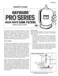
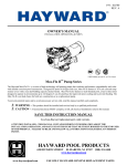
ISDE2423 Rev C
INSTALLATION, OPERATION, & PARTS
PRO-GRID VERTICAL DE FILTER SERIES
MODEL
DE2420
DE3620
DE4820
DE6020
DE7220
EFFECTIVE FILTRATION
RATE
DESIGN FLOW RATE
RECOMMENDED AMOUNT
OF D.E.
FT2
M2
GPM
LPM
LBS
24
2.2
48
182
3.0
36
3.4
72
273
4.5
48
4.5
96
363
6.0
60
5.6
120
454
7.5
72
6.7
144
545
9.0
MAXIMUM WORKING PRESSURE FOR ALL MODELS 50 PSI (3.45 BAR)
KGS
1.4
2.0
2.7
3.4
4.0
ATTENTION INSTALLER: THIS MANUAL CONTAINS IMPORTANT INFORMATION
ON THE OPERATION, AND SAFE USE OF THIS EQUIPMENT.
THIS MANUAL IS INTENDED FOR THE END USER OF THIS PRODUCT
USE ONLY HAYWARD GENUINE REPLACEMENT PARTS
Page 2 of 12
Pro-GridTM VERTICAL D.E. SERIES FILTER
ISDE2423 REV C
This is the safety-alert symbol. When you see this symbol on your equipment or in this manual, look for one of the
following signal words and be alert to the potential for personal injury or death.
WARNING Warns about hazards that could cause serious personal injury or death, and if ignored presents a
potential hazard.
CAUTION Warns about hazards that will or can cause minor or moderate personal injury and if ignored presents a
potential hazard. It can also make consumers aware of actions that are unpredictable and unsafe.
The NOTICE label indicates special instructions that are important but not related to hazards.
READ, UNDERSTAND, AND FOLLOW ALL SAFETY AND OPERATION
INSTRUCTIONS. FAILURE TO FOLLOW SAFETY AND OPERATION INSTRUCTIONS CAN RESULT
IN SEVERE PERSONAL INJURY OR DEATH.
CAUTION To reduce risk of injury, do not permit children to use or climb on this product. Closely
supervise children at all times. The ANSI/NSPI-4 Standard (above-ground and on-ground pools) advises that
components such as the filtration system, pumps, and heaters be positioned to prevent their being used as a
means of access to the pool by young children.
WARNING COMPONENT SEPARATION HAZARD
Pool and spa water circulation systems operate under hazardous pressure during start up, normal
operation, and possibly after pump shut off. Pressure in system can cause explosive component
separation of the upper filter body if safety and operation instructions are not followed. Severe
personal injury or death can result.
This product should be installed and serviced only by a qualified pool professional.
TO AVOID COMPONENT SEPARATION
•
•
•
•
•
•
•
•
•
•
•
•
Follow all safety and operation instructions.
Do not operate water circulation system if a system component is assembled improperly, damaged, missing, or not a
genuine Hayward component.
Before performing maintenance on the water circulation system, verify all system and pump controls are in OFF position
and filter manual air relief valve is in the OPEN position.
Use ONLY Hayward clamp system components: DEX2421JKIT clamp assembly, DEX2421J2 nut/bolt assembly, and a
DEX2422Z2 metal reinforced seal.
Non-Hayward components may fail in use and cause explosive separation.
Never rely on hand tightening the clamp nut to the clamp bolt. Using a ¾” socket on a torque wrench, torque clamp nut
and clamp bolt to 150 inch-lbs.
Before starting system pump, insure filter manual air relief valve body is in LOCK position in filter upper body.
Before starting the system pump, verify that all system valves are set in a position to allow water from the filter to return
back to the pool.
Before starting the system pump, the manual air relief valve must be in the OPEN position.
When starting pump, do not stand over or near filter.
If water leakage appears in the area of the filter tank clamp, immediately turn off all system circulation pumps and
electrical power. Do not return to the filter until all water flow has stopped. Reassemble the clamp system per the
instructions in this owner’s manual to stop the leak.
Return to filter to close manual air relief valve only when a steady stream of water (Not air or air and water mix) is
discharged from the manual air relief valve.
Do not change filter control valve position while system pump is running.
WARNING EXCESS PRESSURE HAZARD
Pressure testing of the pump and filter system in excess of the 50 PSI can cause explosive separation
of the components. Component separation can result in severe personal injury or death.
WARNING ELECTROCUTION HAZARD
High Voltage electricity is present in the pool and spa equipment. High voltage electricity can cause
shock and electrocution. Shock and electrocution can result in severe personal injury or death.
•
•
•
•
•
All electrical wiring MUST be in conformance with applicable local codes, regulations and the
National Electrical Code (NEC).
Before performing any service or maintenance on electrical equipment turn off all electrical power.
Contact a licensed electrician or building inspector for information on local electrical codes for bonding requirements.
Verify water discharge from the filter manual air relief valve is directed away from electrical devices.
Do not locate pump controls over or near filter.
USE ONLY HAYWARD GENUINE REPLACEMENT PARTS
Page 3 of 12
Pro-GridTM VERTICAL D.E. SERIES FILTER
ISDE2423 REV C
WARNING – SUCTION ENTRAPMENT HAZARD.
Suction in suction outlets and/or suction outlet covers that are, damaged, broken, cracked,
missing, or unsecured can cause severe injury and/or death due to the following entrapment
hazards:
Hair Entrapment- Hair can become entangled in suction outlet cover.
Limb Entrapment- A limb inserted into an opening of a suction outlet sump or suction outlet
cover that is damaged, broken, cracked, missing, or not securely attached can result in a
mechanical bind or swelling of the limb.
Body Suction Entrapment- A negative pressure applied to a large portion of the body or
limbs can result in an entrapment.
Evisceration/ Disembowelment Entrapment- A negative pressure applied directly to the
intestines through an unprotected suction outlet sump or suction outlet cover that is,
damaged, broken, cracked, missing, or unsecured can result in evisceration/
disembowelment entrapment.
Mechanical Entrapment- There is potential for jewelry, swimsuit, hair decorations, finger,
toe or knuckle to be caught in an opening of a suction outlet cover resulting in mechanical
entrapment.
TO REDUCE THE RISK OF ENTRAPMENT HAZARDS:
•
•
•
•
•
•
•
•
•
•
A minimum of two functioning suction outlets per pump must be installed. Suction outlets
in the same plane (i.e. floor or wall), must be installed a minimum of three feet (3’)
[.94 meter] apart, as measured from near point to near point.
Dual suction outlets shall be placed in such locations and distances to avoid “dual
blockage” by a user.
Dual suction outlets shall not be located on seating areas or on the backrest for such
seating areas.
The pool or spa circulation system shall be designed to comply with ANSI/APSP-7 2006.
Suction outlet covers shall conform to ANSI/ASME A112.19.8
Never use Pool or Spa if any suction outlet component (cover/grate) is damaged, broken,
cracked, missing, or not securely attached.
Immediately replace damaged, broken, cracked, missing, or not securely attached suction
outlet components.
The CPSP as well as the ICC International Residential Code Part IX, Appendix G, Section
AG106 specifies the installation of a safety vacuum release system conforming to ASME
A112.19.17, or an approved gravity drain system.
Failure to remove pressure test plugs and/or plugs used in winterization of the pool/spa
from the suction outlets can result in an increased potential for suction entrapment.
Failure to keep suction outlet components clear of debris, such as leaves, dirt, hair, paper
and other material can result in an increased potential for suction entrapment.
Suction outlet covers and grates have a finite life. They should be inspected frequently
and replaced within specified life.
USE ONLY HAYWARD GENUINE REPLACEMENT PARTS
Page 4 of 12
Pro-GridTM VERTICAL D.E. SERIES FILTER
GENERAL INFORMATION
ISDE2423 REV C
Your Hayward Pro-GridTM Vertical Grid D.E. Filter combines superior water filtration with ease of operation and totally
corrosion-free construction. It uses diatomaceous earth (D.E.), which is the most efficient dirt remover and filter medium
known.
The D.E., which is usually fed through the skimmer at initial start-up, uniformly coats the curved vertical filter elements
that are covered with a custom fitted monofilament polypropylene filter cloth. As pool water is pumped through the
control valve into the bottom of the filter tank, the D.E. surface, or coating, filters out even the minutest particles
resulting in clear, clean, sparkling water.
After a period of time, the accumulated dirt in the filter causes a resistance to flow, the pressure rises, and flow
diminishes. This means the dirt holding capacity of the D.E. has been reached, and it is time to clean (backwash) your
filter. With the control valve in the back wash position, the water is automatically reversed through the filter, flushing
trapped dirt, debris and D.E. out the waste line. Once the filter is backwashed (cleaned) of D.E. and dirt, the control
valve is manually re-sequenced to filter position and a fresh charge of D.E. is added to resume normal filtering.
A
DE2420
DE3620
DE4820
DE6020
DE7220
IN
32.0
34.1
40.1
46.1
52.0
CM
81
87
102
107
132
REQUIRED CLEARANCE
“B” SIDE
“C” ABOVE
IN
CM
IN
CM
18
46
15
38
18
46
16
41
18
46
18
46
18
46
22
56
18
46
25
63
INSTALLATION
WARNING
This product should be installed and serviced only by a
qualified professional.
Only simple tools (screwdriver and wrenches), plus pipe sealant
for plastic adapters, are required to install and/or service the
filter.
1. The filter system should be installed on a level concrete slab
or other rigid base. Select a well drained and vented area,
one that does not flood when it rains. Position the filter so
that the piping connections, and winter drain are convenient
and accessible for operation, service, maintenance and
winterizing.
2. Position filter so the filter will drain by gravity.
3. If practical, place pump and filter in the shade to shield it
from continuous, direct heat from the sun.
4. Assemble appropriate Filter Control valve (See Page 10 for
selection) to filter. Lubricate the O-ring first (we recommend
using Jack’s 327 Lubricant). Align the two (2) valve pipe
connections, with O-rings in place, with the two openings in
the side of the filter tank and press in firmly. Secure the
assembly to the tank connections with the two bulkhead lock
nuts. Do not over-tighten.
5. Connect the pool suction plumbing between the skimmer,
pool outlet and the pump.
6. Install the pool return plumbing.
7. If pressure gauge is not installed, apply Teflon tape to the
gauge threads and carefully screw the gauge into the gauge
adapter assembly.
8. Do not locate pump controls over or near filter.
9. Verify water discharge from the filter manual air relief valve is
directed away from electrical devices
USE ONLY HAYWARD GENUINE REPLACEMENT PARTS
Pro-GridTM VERTICAL D.E. SERIES FILTER
Page 5 of 12
ISDE2423 REV C
STARTING THE PUMP and FILTER SYSTEM
WARNING
Before Starting the Pump
1. Use ONLY Hayward clamp system components; DEX2421JKIT clamp system, DEX2421J2 nut/bolt assembly,
DEX2422Z2 metal reinforced seal. Non-Hayward clamp components may fail in use and cause explosive
component separation. Verify that upper and lower filter bodies are properly secured with the filter body clamp.
Never rely on hand tightening the clamp nut to the clamp bolt. Using a ¾” socket on a torque wrench, torque clamp
nut to clamp bolt to 150 inch-lbs. Verify that the filter manual air relief body is in the LOCK position, and no filter
components are missing, damaged or not genuine Hayward components. (See Fig 2)
2. Close filter drain. Note: Filter plug requires an o-ring seal. (See Fig 4)
3. Open all system valves to allow water from the pool to the filtration system and from the filter to return to the pool.
4. Place the manual air relief valve in OPEN position. (See Fig 2)
Starting Pump
1. When starting system pump, do not stand over or near filter. If water leakage appears at filter tank clamp,
immediately turn off all system circulation pumps and all electrical power. Do not return to the filter until all water
leakage has stopped.
Reassemble the clamp system per the instructions on page 7 in this owner’s manual to stop leak.
2. Return to filter to CLOSE manual air relief valve only when a steady stream of water (not air or, air and water mix) is
discharged from the manual air relief valve.
3. To avoid damages to the grid elements, DO NOT operate the filter for more than a minute or two without the D.E.
pre-coat.
CLAMP NUT
Manual Air Relief Shown Open
In Locked Position
Tighten clamp bolt
and nut using a
torque wrench to
150 inch-lbs.
CLAMP BOLT
Figure 1
Figure 2
Pre-Coating
Add the correct amount of D.E. (see specifications on the front page of this manual or on the filter label) into the system
through the skimmer – as fast as the plumbing will take it. Record the pressure gauge reading after the D.E. has been
added. This is the “pre-coat” or “clean” pressure.
OPERATION
WARNING
FILTERING
Filtration starts as soon as the filter has been pre-coated. As the filter removes
dirt from the pool water, the accumulated dirt causes a resistance to flow. As a
result, the gauge pressure will rise and the flow will decrease. When the
pressure rises 8-10 psi (.55-.69 bar) above the pre-coat pressure, it is time to
backwash (clean) the filter. Once your filter is running and there is a pressure
reading, line up the green arrow with the current reading. (See Fig 3) When the
pressure rises to or above the red or second arrow, it is time to clean your filter.
Note: During initial clean-up of the pool, particularly with a new pool or a very
dirty pool, it may be necessary to backwash more frequently due to the heavy
initial dirt load in the water.
Figure 3
USE ONLY HAYWARD GENUINE REPLACEMENT PARTS
Page 6 of 12
Pro-GridTM VERTICAL D.E. SERIES FILTER
ISDE2423 REV C
To prevent unnecessary strain on piping system and valves, always shut off pump before switching Filter
Control Valve positions.
FILTER CONTROL VALVE FUNCTIONS
Six-Position Vari-FloTM Filter Control Valve SP0710XR50 or SP0715XR50
(A) FILTER – Set valve to FILTER for normal filtering. Also use for regular Vacuuming.
(B) BACKWASH –
a. Shut off the pump.
b. Set Filter Control Valve to BACKWASH.
c. Start Pump and backwash approximately two minutes, or until water out waste line appears clean.
d. Shut off pump.
e. Set Control Valve to RINSE.
f. Start pump and operate for 20 seconds.
g. Shut off pump.
h. Set Filter control valve to FILTER.
i. Proceed as in Pre-Coating to add fresh D.E.
(C) RINSE – Water Flows through the filter the same as in FILTER position, except that the water goes to WASTE. An optimal
position used for pre-coating if a large cloud (pre-coat puff) is observed returning to pool during the pre-coating process.
(D) WASTE – To bypass filter for draining or lowering water level and for vacuuming heavy debris directly to WASTE.
(E) RECIRCULATE – Water is re-circulated through the pool system, bypassing the filter.
(F) CLOSED – Shuts off flow from pump to filter.
Four Position Selecta-FloTM Filter Control Valve SP0740DE
(A) FILTER– Set valve to FILTER for normal filtering. Also use for regular Vacuuming.
(B) WASTE– To bypass filter for draining or lowering water level and for vacuuming heavy debris directly to WASTE.
(C) BACKWASH–
a. Shut off the pump.
b. Set Filter Control Valve to BACKWASH.
c. Start Pump and backwash approximately two minutes, or until water out waste line appears clean.
d. Shut off pump
e. Set Filter control valve to FILTER.
f. Proceed as in Pre-Coating to add fresh D.E.
(D) POOL OR SPA BOOST - Water is re-circulated through the pool system, bypassing the filter.
Two-Position Slide Valve SP0410X502S
(A) FILTER – Set Valve to FILTER for normal filtering. Also use for vacuuming (Handle in Down position).
(B) BACKWASH –
a. Shut off the pump.
b. Set valve to BACKWASH (UP position).
c. Start Pump and backwash approximately two minutes, or until water out waste line appears clean.
d. Shut off pump
e. Set Filter control valve to FILTER (DOWN Position).
f. Proceed as in Pre-Coating to add fresh D.E. for cleaning filter (Handle in Up position)
MANUAL CLEANING
Before manually cleaning the filter, backwash by following BACKWASHING instructions under each type of
valve.
WARNING
This product should be installed and serviced only by a qualified professional.
FILTER DISASSEMBLY INSTRUCTIONS
1. Turn off all system circulation pumps and all electric power on the pad.
2. Set all system valves in a position to prevent water flow to the filter.
3. The manual air relief valve must be placed in the OPEN position. (FIG 6)
4. Remove filter drain plug (FIG 4) and drain water from filter.
5. Using 3/4” wrenches, loosen and remove the clamp nut and the clamp bolt. (Fig 5)
6. Holding both ends of the filter body clamp carefully spread the clamp ends. Remove the clamp by lifting over the
upper filter body. Do not to drop the clamp during removal because the clamp could be damaged. Do not strike the
clamp with metal tools as they can damage the clamp.
7. Lift off upper filter body. Do not use the pressure gauge to lift the upper filter body.
USE ONLY HAYWARD GENUINE REPLACEMENT PARTS
Page 7 of 12
Pro-GridTM VERTICAL D.E. SERIES FILTER
ISDE2423 REV C
INITIAL CLEANING OF ELEMENT CLUSTER ASSEMBLY
Before removing the element cluster assembly we recommend hosing it
down with a strong stream from a garden hose or preferably with the
Hayward cleaning wand (EC2024). Be sure the drain plug is not in place
or the drain valve is open. Remove as much of the dirty D.E. and
accumulated debris by flushing it out of the drain opening. This will
allow for easier removal of the element cluster assembly.
REMOVING ELEMENT CLUSTER
Rock the element cluster assembly slightly from side to side to free the
manifold from the vertical outlet elbow. The element cluster assembly
may now be removed by lifting it straight up using the lift handles.
CLEANING ELEMENT CLUSTER
Figure 4
The filter element cluster can be cleaned by washing inside and outside
with a garden hose. After hosing filter element cluster, for best results,
carefully brush the surface to remove fine particles. Do Not Pressure
Wash as it can damage the filter element cluster.
You may find some debris on the filter element cluster, which may not
have been removed with hosing.
Clamp Nut
Figure 5
Figure 6
Clamp Bolt
Manual Air Relief Shown in Open
FILTER RE-ASSEMBLY INSTRUCTIONS
WARNING
CLEAN SEAL RING AND SEAL SURFACE
1. Remove filter tank seal.
2. With a clean cloth wipe the lower filter body seal surface. (Fig 4) Do not use a solvent.
3. With a clean cloth wipe the upper filter body seal surface.
Notice: •Do not use any petroleum solvents to clean filter components.
•Do not lubricate DEX2422Z2 Seal.
RE-INSTALLING ELEMENT CLUSTER
1. Lubricate outlet elbow O-rings with Jack’s Formula 327 Multilube.
2. Replace filter element cluster into filter tank, carefully fitting top collector manifold outlet over outlet elbow O-ring.
USE ONLY HAYWARD GENUINE REPLACEMENT PARTS
Page 8 of 12
Pro-GridTM VERTICAL D.E. SERIES FILTER
ISDE2423 REV C
WARNING
This product should be installed and serviced only by a
qualified professional.
BODY AND CLAMP RE-ASSEMBLY
1. Place the metal reinforced seal on the lower filter body (Fig 4).
Place the upper filter body on the Hayward DEX2422Z2 metal
reinforced seal and lower filter body in a position which allows
all operation and safety labels to be clearly visible and the
upper body to be centered on the lower filter body. Press
down firmly and evenly to set the upper filter body. (Fig 7)
2.
Replace the filter clamp around the upper and lower filter
bodies. Hold the clamp ends to position the clamp on the filter
bodies with the clamp ends adjacent to the safety and
operation labels on the filter bodies. (Fig 7)
DO NOT HIT OR STRIKE CLAMP WITH
HAMMER OR METAL TOOLS.
3.
4.
5.
Figure 7
Insert clamp bolt through the clamp ends and thread the clamp
nut onto clamp bolt with rounded end of the nut (Fig 8) towards
the ends of the clamp.
Never rely on hand tightening of clamp nut to clamp bolt.
Using a ¾” socket on a torque wrench, torque clamp nut to
clamp bolt to 150 inch-lbs. (Fig 9).
Follow Operation Instructions for “Starting the Pump and Filter
System” (Page 5).
Clamp Bolt
VACUUMING
Vacuuming can be performed directly into the filter whenever
needed. Backwash filter after vacuuming, if required.
Clamp Nut
Figure 8
Tighten clamp
bolt and nut
using a
torque
wrench to 150
inch-lbs.
Clamp Bolt
Clamp Nut
Figure 9
USE ONLY HAYWARD GENUINE REPLACEMENT PARTS
Pro-GridTM VERTICAL D.E. SERIES FILTER
Page 9 of 12
ISDE2423 REV C
REMOVING THE MANUAL AIR RELIEF VALVE
WARNING
Your Filter comes with a Manual Air Relief Valve (MAR) pre-installed from the
factory.
Only qualified pool professionals should service your filter’s Manual Air
Relief Valve.
For Qualified pool professionals only: If MAR valve needs to be serviced, follow
these instructions carefully.
1. Turn off all system circulation pumps and all electric power on the pad.
2. Set all system valves in a position to prevent water from flowing to the filter.
3. The manual air relief valve must be placed in the OPEN position.
4. Wait until all water leakage has stopped.
5. Grasp the MAR body at the flats, turn the MAR counterclockwise until the
indicator on the on the MAR flange is aligned with the “UNLOCK” position on
the upper filter body.
6. Pull straight up to remove the MAR, a slight rocking motion may help.
Figure 10
Manual Air Relief Shown Open
In Locked Position
Rotate counterclockwise to UNLOCK
RE-INSTALLATION OF THE MANUAL AIR RELIEF VALVE
1.
2.
3.
4.
5.
6.
Check the o-ring seals, replace as needed.
With a clean cloth, wipe upper filter body and o-ring groove. Remove all dirt and debris.
Align the notch in the MAR Flange with notch on top of the upper filter body.
Press the MAR straight down into the upper filter body
Turn the MAR clockwise until the indicator is aligned with the “LOCK” position on the upper filter body.
Verify the MAR discharge points away from all electrical connections.
WINTERIZING FILTER
In areas where subfreezing temperatures can be expected, the filter should be drained to protect the filter from
damage.
1. The filter should be disassembled and the filter cartridges elements cleaned or replaced.
2. Follow directions under FILTER DISASSEMBLY INSTRUCTIONS
3. Then REMOVING CARTRIDGES per instructions
4. Reassemble per the instructions on Page 8.
5. Be sure to leave the drain plug unattached during the winter season to avoid cracking the filter body.
SERVICE AND REPAIRS
Consult your local authorized Hayward dealer or service center. No returns may be made directly to the factory without
the expressed written authorization of Hayward Pool Products.
SUGGESTED POOL CHEMISTRY LEVELS
pH
7.2 to 7.8
TOTAL ALKALINITY
80 to 120 ppm
CALCIUM HARDNESS
200 to 400 ppm
COMBINED CHLORINE
.2 ppm Maximum
CHLORINE (STABILIZED)
1.0 to 3.0 ppm
CHLORINE STABILIZER
60 to 80 ppm
(Cyanuric Acid)
PROBLEM SOLVING LIST
LOW WATER FLOW
REMEDY
1. Check skimmer and pump strainer
baskets for debris.
2. Check for restrictions in intake
and discharge lines.
3. Check for air leak in intake line
(indicated by bubbles returning to
pool).
SHORT FILTER CYCLES
1.
Check for algae in pool and superchlorinate as required.
2.
Be sure chlorine and pH levels are
in proper range (adjust as required).
POOL WATER WON’T CLEAR UP
1.
Check chlorine, pH and total alkalinity
levels and adjust as required.
2.
Be sure flow rate through filter is
sufficient.
3.
Operate filter for longer periods.
4. Backwash (Clean) Filter
USE ONLY HAYWARD GENUINE REPLACEMENT PARTS
Page 10 of 12
ITEM
Pro-GridTM VERTICAL D.E. SERIES FILTER
Part No.
Description
7
CCX1000V
DEX2420MAR2
ECX2712B1
DEX2420Z8A
CCX1000N
DEX2420BT
DEX3620BT
DEX4820BT
DEX6020BT
DEX7220BT
DEX2420LA6PAK
8
DEX2421JKIT
9
10
11
12
13
14
15
DEX2421J2
DEX2420LA6PAK
DEX2422Z2
ECX176865
ECX1109
DEX2400C
DEX2400R
DEX3600R
DEX4800R
DEX6000R
DEX7200R
DEX2400CR
Manual Air Relief w/O-ring
Manual Air Relief Assembly
Pressure Gauge
O-Ring Kit (Set of 2)
Manual Air Relief Nut
Upper Filter Body DE2420
Upper Filter Body DE3620
Upper Filter Body DE4820
Upper Filter Body DE6020
Upper Filter Body DE7220
Label Pack*
Clamp System including:
Clamp, Clamp nut and Bolt,
Hang tag, Metal Reinforced
Seal and Labels
Clamp Bolt and Nut
Label Pack*
Metal Reinforced Seal
Retainer Nut 5/16”-18
Washer (2 Required)
Top Collector Manifold
Retainer Rod DE2420
Retainer Rod DE3620
Retainer Rod DE4820
Retainer Rod DE6020
Retainer Rod DE7220
Flex Air Relief Assembly
Outlet Elbow O-ring
Outlet Elbow DE2420
Outlet Elbow DE3620
Outlet Elbow DE4820
Outlet Elbow DE6020
Outlet Elbow DE7220
1
2
3
4
5
6
16
17
22
DEX2400Z5
DEX2420EA
DEX3620EA
DEX4820EA
DEX6020EA
DEX7220EA
DEX2420DC
DEX3600DC
DEX4800DC
DEX6000DC
DEX7200DC
DEX2400DA
DEX3600DA
DEX4800DA
DEX6000DA
DEX7200DA
DEX2400DS
DEX3600DS
DEX4800DS
DEX6000DS
DEX7200DS
DEX2420GA
23
DEX2420T
24
25
26
27
28
29
DEX2400H
SX220Z2
DEX2420F
DEX2420AT
DEX2420LA6PAK
SP1022C
30
DEX2420DCKIT
31
SX200Z4
SP0740DE
SP0710XR50
SP0715XR50
18
19
20
21
32
33
SP0410X5025
ISDE2423 REV C
Filter Element Cluster
Assembly (Complete set of
elements, collectors,
Locators, Manifold, ect.
Filter Element
(7 Required)
Filter Element Short
(1 Required)
Inlet Diffuser
Element Spacer
(DE2420 Only)
Filter Element Locator
Bulkhead O-Ring (2 Req.)
Bulkhead Fitting (2 Req.)
Lower Filter Body
Label Pack*
1 ½” Drain Plug w/ O-Ring
Strap Kit (Optional)
2 straps, 2 Screws
O-Ring (2 Req.)
Selecta-Flo™ Valve 2” SKT
Vari-Flo™ Valve 1 ½” NPT
Vari-Flo™ Valve 2” NPT
(Optional)
Slide Valve 2” SKT
(Optional)
*Label Pack: Includes all Warning and Operation Labels, Hang Tag, Wire Tie
and Owner’s Manual
USE ONLY HAYWARD GENUINE REPLACEMENT PARTS
Page 11 of 12
Pro-GridTM VERTICAL D.E. SERIES FILTER
ISDE2423 REV C
HAYWARD® LIMITED WARRANTY
This equipment was inspected before shipment from our plant. To original purchasers of this equipment, Hayward
Pool Products, 620 Division Street, Elizabeth, New Jersey, warrants its products free from defects in materials and
workmanship for a period of ONE (1) year from the date of purchase.
Parts which fail or become defective during the warranty period, except as a result of freezing, negligence, improper
installation, use, or care, shall be repaired or replaced, at our option, without charge, within 90 days of the receipt of
defective product, barring unforeseen delays.
To obtain warranty replacements or repair, defective components or parts should be returned, transportation paid, to
the place of purchase, or to the nearest authorized Hayward service center. For further Hayward dealer or service
center information, contact Hayward customer service department. No returns may be made directly to the factory
without the express written authorization of Hayward Pool Products.
To original purchasers of this equipment, Hayward Pool Products warrants its vacuum release systems to be free
from defects in materials and workmanship for a period of ONE (1) year from the date of purchase.
Filters which become defective during the warranty period, except as a result of freezing, negligence, improper
installation, use or care, shall be repaired or replaced, at our option, without charge.
All other conditions and terms of the standard warranty apply.
Hayward shall not be responsible for cartage, removal and/or reinstallation labor or any other such costs incurred in
obtaining warranty replacements.
The Hayward Pool Products warranty does not apply to components manufactured by others. For such products, the
warranty established by the respective manufacturer will apply.
Some states do not allow a limitation on how long an implied warranty lasts, or the exclusion or limitation of
incidental or consequential damages, so the above limitation or exclusion may not apply to you.
This warranty gives you specific legal rights, and you may also have other rights, which vary from state to state.
*Supersedes all previous publications.
Hayward Pool Products
620 Division Street
Elizabeth, NJ 07207
USE ONLY HAYWARD GENUINE REPLACEMENT PARTS
Page 12 of 12
Pro-GridTM VERTICAL D.E. SERIES FILTER
ISDE2423 REV C
PRODUCT REGISTRATION
(Retain For Your Records)
DATE OF INSTALLATION ____________________
INITIAL PRESSURE GAUGE READING (CLEAN FILTER)
_______________________
PUMP MODEL ________________
HORSEPOWER
_______________________
FILTER MODEL ________________
SERIAL NUMBER _______________________
DETACH HERE: REGISTER ONLINE AT WWW.HAYWARDNET.COM
or Fill out bottom portion completely and mail within 10 days of purchase/installation.
-----------------------------------------------------------------------------------------------------------Mail to: Hayward Pool Products, 620 Division Street, Elizabeth, NJ 07207, Attn: Warranty Dept.
Please Print Clearly:
Warranty Registration Card
Name__________________________________________________
Purchased Date:____________________________________________
Address________________________________________________
Purchased from: ______________________________________________
City______________________ State_________ Zip____________
Company name________________________________________________
E-mail Address__________________________________________
Address_______________________________________________________
City__________________________ State_________ Zip_______________
Product Purchased ______________________________________
Product Serial No. _______________________________________
□ New Installation
Please send me more information on these other
products from Hayward:
□ Replacement
□ Pump □ Filter □ Automatic Pool Cleaner □ Light
□ Chlorinator □ Skimmer □ Heater □ Heat Pump
□ Salt/Chlorine Generator □ Controls
Type of Pool:
□ Vinyl □ Fiberglass □ Gunite □ Above-ground
Size of Pool__________________________
May we contact you for future product promotions and offerings?
Yes
REGISTER YOUR WARRANTY ON-LINE AT WWW.HAYWARDNET.COM
© Hayward Pool Products. 2008 All rights reserved.
Pomona, CA
Clemmons, NC
Nashville, TN
West Palm Beach, FL
North Kingstown, RI
Oakville, ON, Canada
www.haywardpool.com
St. Vulbas, France
Wuxi, China
No