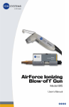
1
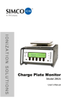
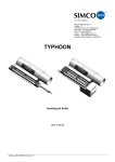
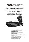
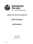
IONIZATION SOLUTIONS AirForce Ionizing Blow-off Gun Model 6115 User’s Manual About Simco-Ion Simco-Ion develops, manufactures, and markets system solutions to manage electrostatic charge. As the world's largest provider of electrostatics management products and services, Simco-Ion improves its customers' business results by providing a total solution to their electrostatic discharge and electromagnetic interference challenges. Simco-Ion is a wholly-owned subsidiary of Illinois Tool Works (ITW) with its Technology Group located in Alameda, California. For more information about Simco-Ion visit www.simco-ion.com or call 800-367-2452. Simco-Ion is ISO 9001 and ANSI ESD S20.20 certified. © 2012 Simco-Ion 19-6115-M-01 Rev 4 Contents 1 Description .......................................................................... 1 1.1 AirForce Ionizing Blow-off Gun Model 6115 ............................................ 2 1.2 Performance and Power Requirements................................................... 5 1.3 Compressed Gas Requirements.............................................................. 6 2 Installation ........................................................................... 7 2.1 Box Contents ........................................................................................... 8 2.2 Mounting .................................................................................................. 9 2.3 Assembling the Components ................................................................. 12 3 Operation ........................................................................... 19 3.1 Before Turning the Unit On .................................................................... 16 3.2 Power Up and Use................................................................................. 17 3.3 Storage .................................................................................................. 18 4 Maintenance ...................................................................... 19 4.1 Maintenance Requirements ................................................................... 20 4.2 Cleaning the Components ..................................................................... 21 4.3 Replacing the Air Filter........................................................................... 22 4.4 Replacing the Emitter Points.................................................................. 23 4.5 Testing ................................................................................................... 25 4.6 Troubleshooting ..................................................................................... 26 5 Specifications.................................................................... 27 6 Warranty & Service ........................................................... 33 19-6115-M-01 Rev 4 1 Description 1.1 AirForce Ionizing Blow-off Gun Model 6115 1.2 Performance and Power Requirements 1.3 Compressed Gas Requirements 19-6115-M-01 Rev 4 1 1.1 AirForce Ionizing Blow-off Gun Model 6115 The AirForce Ionizing Blow-off Gun Model 6115 provides efficient ionization and effectively removes particle contamination, even on the most static-sensitive of products. IsoStat Technology ensures that surface charges are controlled with constantly balanced ionization. The AirForce Gun never needs calibration and requires very little maintenance. Figure 1. AirForce Gun and Console 19-6115-M-01 Rev 4 2 Compact and lightweight, the AirForce console can be mounted anywhere on the workstation for easy access. The console connects to any supply of clean dry air or nitrogen and an internal disposable filter collects any residual particles from the supply. The console, gun, and air hose are static-dissipative and ESD-safe. An extremely low EMI level ensures that the AirForce won’t interfere with other electronic equipment or operations. Figure 2. AirForce Gun 1. Gun 2. Hanging clip 3. Air hose 4. Filter connection 19-6115-M-01 Rev 4 3 Figure 3. AirForce Console 1. 2. 3. 4. 5. 6. Power indication LED Power switch Power receptacle for optional footswitch Filter-hose housing Filter quick-release/lock button Air supply connection 19-6115-M-01 Rev 4 4 1.2 Performance and Power Requirements Performance The AirForce Gun reduces a static charge of ±1000 V down to 100 V in less than one second at a distance of six inches (30-psi / 0.2MPa inlet pressure). Reference the ESD Association ANSI/ESD Standard STM3.1-2000 for test procedure. Balance is within ±30 V of zero at a distance of six inches. Power Requirements The AirForce Gun console requires a 24 VAC power source, which can be provided by wall transformers. Simco-Ion offers three transformers for use with this product: the 14-1306 (100 VAC input), 14-1310 (117 VAC input), and 14-21570 (230 VAC input). To ensure correct usage and continued performance of the wall transformer, please note the following: • The transformer should not be operated beyond the specified electrical limit as described in the Specifications section of this manual. • Damage caused to the transformer from operation in an environment that exceeds the specified limits will void the warranty. • Damage to the transformer or 6115 resulting from the use of the incorrect input voltage for the transformer will void the warranty. 19-6115-M-01 Rev 4 5 1.3 Compressed Gas Requirements Caution: Failure to use clean dry air or nitrogen may result in damage to the AirForce that is not covered under warranty. The air supply must be clean dry air or nitrogen supplied by a delivery system that utilizes a refrigerated dryer or equivalent water removal to achieve a limit of about 550 ppm water vapor at 35°F (1.66°C) Dew Point. To prevent particles from entering the console, a 2 micron coalescing filter or better is recommended upstream of the gun console. Note that the filter in the 6115's console collects small residual particles and aerosols and does not act as a primary filter. The console filter is rated at 0.01 micron for particulates is effective down to 0.008 micron for aerosols. An adequate filter that can be recommended for the inlet of the AirForce Gun would be a Finite Filter Grade 10 Media Specification. This provides a 95% coalescing efficiency for aerosols with a 0.7 micron (and greater) particle retention. This removes gross amounts of particles, water and or oil and aerosols. A Grade 6 Media provides 99.98% efficiency when almost total removal of liquid aerosols and particles are required in all pressure ranges down to 0.01 microns. This would offer the highest protection at the gun without need of frequent change. Fine filters need to be changed more often. 19-6115-M-01 Rev 4 6 2 Installation 2.1 Box Contents 2.2 Mounting 2.3 Assembling the Components 19-6115-M-01 Rev 4 7 2.1 Box Contents The AirForce Gun is supplied with: • Power console • Gun and hose • Bag containing (see Figure below): 1. Interconnect cable (10 feet), part #33-1700-10-GUN 2. Mounting plate, part #32-8380 3. Extra filter, part #91-6115FLT 4. Quick coupling, part #28-5045 5. S-hook and four screws for mounting • Certificate of Compliance • This manual Your product may also contain a power transformer, if ordered, or other optional accessories. Figure 4. Included Accessories 19-6115-M-01 Rev 4 8 2.2 Mounting Choose a location that will be convenient to the work area and the air supply. The console takes up very little space and is adaptable to a variety of permanent or temporary installations. To minimize bends in the gun hose, orient the console so that the open end points toward the work area and the male connector points toward the air supply. Prior to mounting, plug one end of the supplied 10-foot interconnect cable into the jack on the back of the console. Plug the other end of the cable into the unplugged wall transformer. Note: The separate interconnect cable supplied with the Model 6115 is not needed with the 230 VAC transformer, P/N 14-21570. This transformer includes a hardwired interconnect cable. Figure 5. The console may be mounted in a temporary or permanent state, depending on your application and environmental needs. The following instructions describe both mounting methods. Permanent Mounting 1. Attach the supplied mounting plate to the threaded holes on the back of the console, using the supplied screws. See Figure 1. 2. Attach the plate to a flat surface, such as a wall or back of a work bench, using suitable screws and fasteners. When mounting to a hollow wall be sure to use #8 screws and 3/4” length anchors as a minimum. 19-6115-M-01 Rev 4 9 Figure 6. Permanent Mounting Temporary Mounting Units may be mounted with velcro or 3M Dual LockT M strips (available from Simco-Ion). Attach the console to a flat surface. Mounting to an Air Supply When an air supply is close to the work area and fitted with a standard industrial interchange quick coupling, you may attach the console to the air supply fitting directly. If necessary, use a prefilter as defined in section 1.3 Compressed Gas Requirements in Chapter 1. 19-6115-M-01 Rev 4 10 Gooseneck Mounting Stand An optional gooseneck mounting stand (Simco-Ion p/n 33-6115) is available for the AirGun. An instruction sheet accompanies the stand that describes how to install it. The optional footswitch is recommended for use with the gooseneck mounting stand. Figure 7. Optional Gooseneck Mounting Stand 19-6115-M-01 Rev 4 11 2.3 Assembling the Components Caution: Protect the hose from sharp objects, abrasion, and high temperatures. Do not pull or pinch the hose while assembling the components. 1. Insert the larger diameter end of the filter into the end of the flexible air hose connector. Press the metal filter release tab at the end of the hose until it locks into place. See figure below. Figure 8. Inserting the Air Filter 2. Connect the hose and filter to the console. Press the filter release button on the front of the console to lock it down. Push the fitting containing the filter all the way into the opening in the console until it latches with a click. It fits only in the correct orientation. The small plastic fitting on the end of the filter must align with the metal guide coupling in the console. You may have to wiggle the filter slightly while inserting it. See Figure 9. Connecting the Hose and Filter. 19-6115-M-01 Rev 4 12 Figure 9. Connecting the Hose and Filter 3. Attach the included 1/4” NPT female quick connect fitting to your gas supply line. Slide the outer ring on the fitting towards the supply line to insert the mating fitting on the console. You can attach the console directly to the air supply pipe or attach it using a hose (not supplied). If necessary, use a prefilter as defined in the Clean Dry Air Requirements section. 4. Attach the foot switch to the console (optional). If you have purchased the optional foot switch, plug its cable into the jack on top of the console (next to the power switch). 19-6115-M-01 Rev 4 13 19-6115-M-01 Rev 4 14 3 Operation 3.1 Before Turning the Unit On 3.2 Power Up and Use 3.3 Storage 19-6115-M-01 Rev 4 15 3.1 Before Turning the Unit On Before turning on power, ensure the following: • The correct wall transformer is used. The use of an improper wall transformer may result in damage to the unit. See section 1.2 Performance and Power Requirements in Chapter 1 for additional information. • The wall transformer is inserted into a properly grounded AC receptacle. • If the console is not attached to a surface, secure the power cord so that it cannot accidentally pull the console and gun off the work bench. For safety and the most efficient ionization, set the pressure regulator on your air or nitrogen supply between 20 and 65 psi (0.14-0.45 MPa). Discharge times vary depending on air pressure. Caution: Pressures of 30-40 psi (0.2-0.28 MPa) are commonly used for decontaminating surfaces. OSHA regulations recommend limiting hand-held air blow-off devices to maximum pressures of 30 psi (0.2 MPa). The hose is rated at 65 psi (0.45 MPa) at temperatures up to 75°F (24°C), and the rating decreases at higher temperatures. When using high pressures, consider the ambient room temperature as well as heat from surrounding equipment. 19-6115-M-01 Rev 4 16 3.2 Power Up and Use Turn the Power Switch on the console to on. The green LED on the console should illuminate. Caution: Do not switch the power switch on the console on at the same time that the gun trigger is pressed. Hold the gun approximately six inches from the surface you want to blow-off and discharge. Aim the gun and press the trigger to blow ionized air. The green LED on the back of the gun lights up while you press the trigger. Typically, static electricity is discharged within one second. Release the trigger when the surface is clean. If the optional foot switch is installed, you can use either the foot switch or the trigger. Caution: Do not use this equipment with pressure above 65 psi (0.45 MPa). 19-6115-M-01 Rev 4 17 3.3 Storage If the gun won’t be used for some time, turn off the power switch on the console. Use the included hook to hang the gun out of the way but within reach. 19-6115-M-01 Rev 4 18 4 Maintenance 4.1 Maintenance Requirements 4.2 Cleaning the Components 4.3 Replacing the Air Filter 4.4 Replacing the Emitter Points 4.5 Testing 4.5 Testing 4.6 Troubleshooting 19-6115-M-01 Rev 4 19 4.1 Maintenance Requirements The AirForce requires very little maintenance. Occasional cleaning of the case and emitter points, and periodic replacement of the air filter, is all that is required. Always be sure to protect all components from liquids and corrosive chemicals and avoid dropping the gun on hard surfaces. Carefully follow these maintenance instructions Caution: Disconnect power and air supplies before cleaning or replacing components. Recommended Cleaning Materials • Cleanroom-compatible cleaning cloths (polyester cloth is recommended) • Cleanroom-compatible cloth swabs • Cleaning solution of 50% IPA (electronic-grade isopropyl alcohol)/50% de-ionized water or Simco-Ion’s Emitter Point Cleaner (#22-1000) 19-6115-M-01 Rev 4 20 4.2 Cleaning the Components 1. Turn off the console and disconnect it from its power and air supply sources. 2. Using a cloth moistened with the IPA solution, wipe the exterior surfaces of the console and gun to remove any dirt or dust that may have collected. 3. Using a swab moistened with the IPA solution, gently clean the emitter points on the gun. Extremely dirty points increase the time needed to discharge static and can affect the ionization balance. 19-6115-M-01 Rev 4 21 4.3 Replacing the Air Filter Simco-Ion recommends changing the filter every 3 months or when it begins to look dirty. 1. Turn power off at the console and disconnect the console from the air supply. 2. Hold down the filter release button on the side of the console. 3. Remove the hose and filter from the console by pulling the textured rubber plug where the hose emerges from the console. Rocking the plug back and forth can help loosen the filter. Do not pull the hose itself. 4. Remove the filter from the hose fitting by depressing the metal release tab on the fitting and pulling off the filter. 5. Follow the directions in section 2.3 Assembling the Components in Chapter 2 to install the new air filter. 19-6115-M-01 Rev 4 22 4.4 Replacing the Emitter Points The emitter points usually last the life of the unit. Simco-Ion recommends replacement if points are bent, broken or otherwise damaged, or if you cannot remove dirt by cleaning the points with isopropyl alcohol. A replacement clip containing a pair of emitter points is available from Simco-Ion. To replace the points: 1. Disconnect the power and air supplies. 2. Insert the tip of a small screwdriver into the slot on the underside of the gun barrel. See figure below. 3. Using the screwdriver as a lever, loosen the old clip, then grasp it between your thumb and forefinger and detach it from the gun. The emitter point assembly slides straight out. The emitter points are very sharp. Handle carefully and only touch the plastic clip. Figure 10. Replacing the Emitter Points 4. To insert the new clip, hold the gun with the barrel pointing up. 19-6115-M-01 Rev 4 23 5. Grasp the new clip between your thumb and forefinger and align it so the curved edges of the clip match the curve of the inside of the gun barrel. 6. Align the blunt prongs of the emitters with the holes in the barrel and press the clip into place. 7. Press the clip all the way in using the tip of a screwdriver. The clip should fit snugly between the raised rim of the barrel and the raised rim of the air nozzle. If the clip overlaps the air nozzle, it is installed upside down. 19-6115-M-01 Rev 4 24 4.5 Testing To make sure your AirForce Gun is working properly check the balance and discharge levels. Simco-Ion recommends periodic testing with a charge plate monitor (CPM) such Simco-Ion’s Model 280A. Testing should be performed in accordance with the ionization standard ANSI/ESD STM3.1–2000 of the ESD Association. At a line pressure of 30 psi (0.2 MPa), discharge of 1000 V to 100 V should require less than one second and balance should be within 30 V of zero. Refer to the instruction manual for the Model 280A for additional operating information. 19-6115-M-01 Rev 4 25 4.6 Troubleshooting If air is not flowing through the AirForce gun when the trigger is activated, perform the following steps. If these steps do not eliminate the problem, contact Simco-Ion Technical Support ([email protected]). Do not attempt any repair other than that described below. 1. Check that the air supply is on. 2. Check that the air supply connection to the control console is secure. 3. Check the filter connection to the gun and hose. 4. Check the hose and filter connection to the console. Press the filter release button and push the filter fitting into the console until it is properly seated. 5. Make sure the switch on the console is turned on and the power LED is on. If the power LED fails to light, make sure that the transformer is connected to a live receptacle and the the interconnect cable between the console and transformer is securely connected and undamaged. If the transformer is equipped with an IEC power cord, check to make sure it is connected at both ends and in good condition. 19-6115-M-01 Rev 4 26 5 Specifications 5.1 Specifications 5.2 Dimensional Drawings 5.3 Parts & Accessories 19-6115-M-01 Rev 4 27 5.1 Specifications Model 6115 Audible Noise 70 dBA @ 1m, 30 psi (0.2 MPa) Conducted EMI 29 dbV; Ozone < 0.005 ppm (24 hr. accumulation); conforms to OSHA requirements AirGun and Hose Gun Construction Static-dissipative polycarbonate Ion Emission Steady-state DC Emitter Points Tungsten alloy; field replaceable Cleanroom Class Meets ISO 14644-1 Class 4 (Fed Std. 209E Class 10) Indicators Green power LED Air Hose Static-dissipative polyurethane, 3/8” outside diameter; 7’ (213.4 cm)/ 65 psi (0.45 MPa) Gun Hanger 302 stainless steel; optional mounting stand for hands-free operation Dimensions 8.0" L x 3.0" W x 1.0" D (20.3 x 7.6 x 2.5 cm) Weight 12.0 oz. (341 g) with 7' air hose Console Construction Static-dissipative polycarbonate Power Requirement 24 VAC, ±10W powered from transformer Power Indicator Green LED Gas Input 20-65 psi (0.14-0.45 MPa), Clean Dry Air or Nitrogen Gas Connection 1/4” male industrial interchange quick disconnect and 1/4” NPT female coupler Air filter 99.9% efficient, 0.01 micron particles, 0.008 micron coalescing Mounting Metal mounting plate attaches to back of the unit Dimensions 8.5L x 3.0W x 1.6D in. (21.6 x 7.6 x 4.1 cm) Weight 11.5 oz (326 g) Certifications 19-6115-M-01 Rev 4 28 14-1306 Wall Transformer (This desktop transformer requires an optional IEC power cord) Input Voltage 100 VAC ±10%, 50 Hz, 300 mA Output Voltage V(max) 29.0 VAC; full load V(nom) 24 VAC ±5% Output Current 0-1.0A Operating Temp 0- 50°C Short Circuit Protection The power supply is provided with protection against short circuit by means of the primary thermal fuse Certification 14-1310 Wall Transformer Input Voltage 117 VAC ±10%, 60 Hz, 270 mA Output Voltage No load V(max) 29.0 VAC; full load V(nom) 24 VAC ±5% Output Current 0-1.0A Operating Temp 0- 50°C Short Circuit Protection The power supply is provided with protection against short circuit by means of the primary thermal fuse Certification 14-21570 Wall Transformer (This desktop transformer requires an optional IEC power cord) Input Voltage 230 VAC, 10%, 50/60 Hz, 40 VA Output Voltage 24 VAC ±5% Output Current 1670 mA (max) Operating Temp 0-50°C Short Circuit Protection The power supply is provided with protection against short circuit by means of the primary thermal fuse Certification 19-6115-M-01 Rev 4 29 5.2 Dimensional Drawings Wall Transformer P/N 14-1310 Desktop Transformer P/N 14-21570 Note: The separate interconnect cable supplied with the Model 6115 is not needed with the 230 VAC transformer, P/N 14-21570. This transformer includes a hardwired interconnect cable. 19-6115-M-01 Rev 4 30 Transformer P/N 14-1306 19-6115-M-01 Rev 4 31 5.3 Parts & Accessories Replacement and Optional Parts Air Filter, package of three 91-6115FLT Emitter point assembly 91-6115T-EMT Gooseneck mounting stand 33-6115 Footswitch 91-6115SWT 100 VAC Desktop Transformer 14-1306 120 VAC Wall Transformer 14-1310 230 VAC Desktop Transformer 14-21570 Optional Instrumentation Model 280A Charged Plate Monitor (CPM) 91-0280A-C Model 280A CPM Instruction Manual 19-0280A-M 775 Periodic Verification System 91-0775PVS 775 PVS Instruction Manual 19-0775PVS-M 19-6115-M-01 Rev 4 32 6 Warranty & Service Simco-Ion, provides a limited warranty for the AirForce Ionizing Blow-off Gun Model 6115. New products manufactured or sold by Simco-Ion are guaranteed to be free from defects in material or workmanship for a period of two (2) years from date of initial shipment. Simco-Ion liability under its new product warranty is limited to servicing (evaluating, repairing, or replacing) any unit returned to Simco-Ion that has not been subjected to misuse, neglect, lack of routine maintenance, repair, alteration, or accident. In no event shall Simco-Ion be liable for collateral or consequential damages. Consumable items such as, but not exclusive to, emitter points, emitter wires, batteries, filters, fuses or light bulbs are only covered under this warranty if found defective as received with the new product. To obtain service under this warranty, please contact Simco-Ion Technical Support at [email protected] or (510) 2170470. 19-6115-M-01 Rev 4 33 19-6115-M-01 Rev 4 34 Notes 19-6115-M-01 Rev 4 35 Notes 19-6115-M-01 Rev 4 36 Technology Group 1750 North Loop Rd., Ste 100 Alameda, CA USA 94502 Tel: 510-217-0600 Fax: 510-217-0484 Toll free: 800-367-2452 Sales services: 510-217-0460 Tech support: 510-217-0470 [email protected] [email protected] [email protected] [email protected] www.simco-ion.com 19-6115-M-01 Rev 4